Table of Contents
Advertisement
Advertisement
Table of Contents

Related Manuals for ECR Dunkirk PWB Series


Summary of Contents for ECR Dunkirk PWB Series
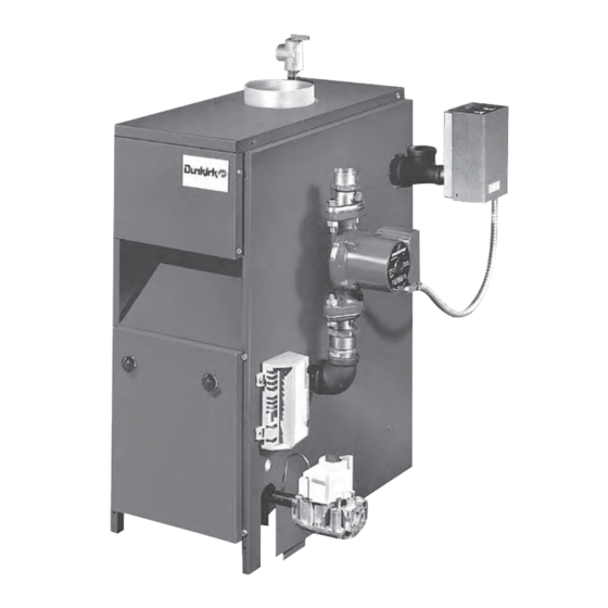
- Page 1 PWB SERIES GAS-FIRED HOT WATER BOILERS MODEL PVWB Continuous Pilot MODEL PWB Electronic Intermittent Ignition ECR International, Inc. 2201 Dwyer Avenue, Utica NY 13501 An ISO 9001-2008 Certified Company P/N 14683002, Rev. A [8/2011] www.ecrinternational.com...
-
Page 2: Boiler Ratings And Capacities
BOILER RATINGS AND CAPACITIES NATURAL AND PROPANE GAS RATINGS BASIC BOILER UNIT NO. Dimensions (Inches) Number Heating Net I=B=R Input Capacity Rating Electronic Ignition Continuous Pilot Flue “A” (1,2) Sections (1,3) (1,4) With Vent Damper With Vent Damper Diameter Width PWB-2D PVWB-2D 37.5... -
Page 3: Before You Start
BEFORE YOU START Check to be sure you have the right size boiler before If this boiler is installed in a building under starting the installation. See rating and capacity table construction, special care must be taken to insure a on previous page. -
Page 4: Fresh Air For Combustion
FRESH AIR FOR COMBUSTION Known Air Infi ltration Rate. See Table 1 WARNING for space with boiler only. Use equation for multiple appliances. Do not use an air Air openings to combustion area must infi ltration rate (ACH) greater than 0.60. not be obstructed. -
Page 5: Installation - System Piping
INSTALLATION - SYSTEM PIPING Figure #1 WARNING Burn and scald hazard. Safety relief valve could discharge steam or hot water during operation. Install discharge piping per these instructions Place boiler in the selected location (as near chimney as possible.) Your boiler is shipped assembled. -
Page 6: For Use With Cooling Units
INSTALLATION - SYSTEM PIPING LOW DESIGN WATER TEMPERATURE SYSTEMS Figure 4 (BELOW 140° F) Install 3-way or 4-way mixing valve (or suitable alternative) to prevent low temperature return water from entering boiler when used in heating system designed for low water temperature (below 140°F, e. - Page 7 INSTALLATION - SYSTEM PIPING FIG. 5 - TYPICAL HOT WATER PIPING FIG. 6 - CHILLED WATER PIPING...
-
Page 8: Chimney And Vent Pipe Connection
CHIMNEY AND VENT PIPE CONNECTION For boilers for connection to gas vents or chimneys, vent installations shall be in accordance with “Venting of Equipment”, of the National Fuel Gas Code, ANSI Z223.1/ NFPA 54, or applicable provisions of local building codes. CHECK YOUR CHIMNEY Run pipe as directly as possible with as few el- This is a very important part of your heating system. -
Page 9: Minimum Vent Pipe Clearance
CHIMNEY AND VENT PIPE CONNECTION 1. Seal any unused openings in the common venting system. MINIMUM VENT PIPE CLEARANCE 2. Visually inspect the venting system for proper Wood and other combustible materials must not be size and horizontal pitch and determine there is no closer than 6”... -
Page 10: Vent Damper Operation
VENT DAMPER OPERATION FIG. 9 FIG. 10 For safe, effi cient operation, the vent damper and all For further information, and for a vent damper fl ue product carrying areas of the appliance must be troubleshooting guide, refer to the manual that was checked annually by you, with particular attention given packaged with the vent damper. -
Page 11: Check Gas Supply
GAS SUPPLY PIPING CHECK GAS SUPPLY FIG. 12 GAS PIPE SIZES The gas pipe to your boiler must be correct size for NATURAL GAS length of run and for total BTU per hour input of all gas Pipe Capacity - BTU Per Hour Input utilization equipment connected to it. -
Page 12: Electric Power Supply
ELECTRICAL WIRING Electrical work must be in accordance with require- Locate the thermostat about fi ve feet above the fl oor ments of authority having jurisdiction or, in absence on an inside wall. It may be mounted directly on the of such requirements, with National Electrical Code, wall or on a vertically mounted outlet box. - Page 13 WIRING DIAGRAMS FOR HOT WATER BOILERS INTERMITTENT IGNITION 4 POLE CONNECTOR VENT DAMPER CABLE 24 V. THERMOSTAT 6 POLE CONNECTOR L8148E1257 AQUASTAT P2-01 P1-01 P2-05 P1-02 FUSE 24 V. SECONDARY P2-03 VENT DAMPER 120 V. PRIMARY P2-04 P1-04 P2-02 P1-03 CIRCULATOR PUMP Note: S1A and S1B are the NEUTRAL...
-
Page 14: Standing Pilot
WIRING DIAGRAMS FOR HOT WATER BOILERS STANDING PILOT Note: S1A and S1B are the automatic operation/hold damper open switch. Switch is shown in automatic position. S2, S3 and S4 are cam actuated snap switches. Fuse blows fi rst time thermostat closes after vent damper is plugged in. - Page 15 EQUIPMENT AND OPTIONAL ACCESSORIES - WHAT THEY DO SAFETY RELIEF VALVE AIR ELIMINATING FITTING (AIR PURGER) You must have a safety relief valve on your boiler. An air purger is used to remove excess air from Water expands as it is heated. If there is no place the system.
-
Page 16: Rollout Switch
EQUIPMENT AND OPTIONAL ACCESSORIES - WHAT THEY DO ROLLOUT SWITCH SPILL SWITCH (FLAME ROLLOUT SAFETY SHUTOFF) (BLOCKED VENT SAFETY SHUTOFF) The rollout switch is a temperature-sensitive fuse link The spill switch is a manual reset disc thermostat with device. It is located on the boiler base just outside a fi... -
Page 17: For Your Safety Read Before Operating
FOR YOUR SAFETY READ BEFORE OPERATING WARNING If you do not follow these instructions exactly, a fi re or explosion may result causing property damage, personal injury or loss of life. WHAT TO DO IF YOU SMELL GAS • Do not try to light any appliance. A. - Page 18 CONTINUOUS PILOT BOILER - VR8200A/VR8300A GAS VALVE OPERATING INSTRUCTIONS 1. STOP! Read the safety information on page 17. 9. Rotate the gas control knob counterclockwise to “PILOT” Push down and hold the red reset button 2. Set the thermostat to lowest setting. while you light pilot burner with a match.
-
Page 19: Main Burners
OPERATING YOUR BOILER FIG. 14 - LIGHTING PILOT FIG. 15 -VR8200A/VR8300A AUTOMATIC GAS VALVE FIG. 16 -VR8204A/VR8304M AUTOMATIC GAS VALVE WIRING PRESSURE REGULATOR ADJUSTMENT TERMINALS (2) (UNDER CAP SCREW) FIG. 17 OUTLET PRESSUR INLET PRESSURE GROUND TERMINAL OUTLET INLET PILOT OUTLET PILOT ADJUSTMENT GAS CONTROL KNOB... -
Page 20: Expansion Tank
MAINTAINING YOUR BOILER BURNERS VENT PIPE A visual check of the pilot end main burner fl ames The venting of this unit is very important and the should be made at least once each year, preferably at piping should be checked at least once a season. If the beginning of the heating season. -
Page 21: Service Hints
SERVICE HINTS EQUIPMENT AND OPTIONAL ACCESSORIES - WHAT THEY DO You may avoid inconvenience and service calls by checking these points before you call for service. CAUTION WHAT TO DO IF YOU SMELL GAS • Do not try to light any appliance. •... -
Page 22: Repair Parts
REPAIR PARTS GAS – FIRED HOT WATER BOILERS – IMPORTANT – READ THESE INSTRUCTIONS BEFORE ORDERING All parts are listed in the following Parts List may be ordered through your nearest supplier. When ordering parts, fi rst obtain the Model Number from the data plate on your boiler, than determine the Part No. - Page 23 REPAIR PARTS FOR USE WITH NATURAL GAS ONLY NOTE: Actual gas valve may look different than gas valve shown BURNER & MANIFOLD PARTS This is a repair parts list – NOT a packing list! PART NUMBERS FOR DESCRIPTION 2 Section 3 Section 4 Section 5 Section...
- Page 24 REPAIR PARTS BOILER CONTROLS AND PIPING Part Description ¾” ASME Relief Valve 14622011 ¾” x 6½” Nipple 14607002 Temperature Pressure Gauge - 1260006SP 2” shank Tee, 1¼” x 1¼” x ¾”, Black PF05901 Iron Bushing, ¾” x ¼”, Black 1060002 Iron Nipple, 1¼”...
- Page 25 NOTES...
- Page 26 NOTES...
- Page 28 ECR International, Inc. 2201 Dwyer Avenue, Utica NY 13501 www.ecrinternational.com...
Need help?
Do you have a question about the Dunkirk PWB Series and is the answer not in the manual?
Questions and answers
Can precipitate form in the boiler and creat strange noise ? Do I need to drain the water of the boiler to get rid the precipitate?