Table of Contents
Advertisement
Quick Links
Models
15B045FE
15B070FE
15B096FE
15B120FE
15B145FE
15B170FE
15B195FE
15B245FE
15B295FE
For Natural Gas Or Propane
An ISO 9001-2008 Certified Company
C.S.A. Certified
Tested For 100 psi
Working Pressure
15B SERIES
Cast Iron Gas Fired Boilers
For Forced Hot Water
INSTALLATION, OPERATION &
MAINTENANCE MANUAL
ASME
II
Manufactured by:
ECR International, Inc.
2201 Dwyer Avenue,
Utica NY 13501
web site: www.ecrinternational.com
P/N 240009024, Rev. B [12/2013]
Advertisement
Table of Contents

Subscribe to Our Youtube Channel
Related Manuals for ECR Pennco 15B045FE


Summary of Contents for ECR Pennco 15B045FE
- Page 1 15B245FE 15B295FE C.S.A. Certified Tested For 100 psi ASME For Natural Gas Or Propane Working Pressure Manufactured by: ECR International, Inc. 2201 Dwyer Avenue, Utica NY 13501 web site: www.ecrinternational.com An ISO 9001-2008 Certified Company P/N 240009024, Rev. B [12/2013]...
-
Page 2: Table Of Contents
TABLE OF CONTENTS 1 - Ratings & Data - Natural Gas & Propane Gas ............4 2 - Dimensions ......................5 3 - Installation Procedure ....................6 4 - Ventilation & Combustion Air ..................7 5 - Connecting Supply & Return Piping .................8 6 - Vent Installation ....................14 7 - Vent System Modification ..................14 8 - Vent Damper Installation &... - Page 3 SAFETY MESSAGES KEEP THIS MANUAL NEAR BOILER IMPORTANT: Read the following instructions RETAIN FOR FUTURE REFERENCE COMPLETELY before installing!! WARNING Safety Symbols & Warnings The following defined symbols are used throughout this Fire, explosion, asphyxiation and electrical shock manual to notify the reader of potential hazards of varying hazard.
-
Page 4: Ratings & Data - Natural Gas & Propane Gas
1 - RATINGS & DATA - NATURAL GAS & PROPANE GAS - Ratings and Capacities Table 1 Heating Net AHRI Water Input AFUE Elect. No. Of Recommended Air Capacity Rating Water Content Model No. Ign. Burners Cushion Tank (Gals.) 15B045 82.0% 15B070 82.0%... -
Page 5: Dimensions
2 - DIMENSIONS Dimensions Table 2 - Dimensions Dimensions (Inches) Natural Gas Pump Size Supply & Model No. Inlet* Return Tappings 15B045 ½" 11¼ 5⅝ 27⅛ 20 1¼" 15B070 ½" 15⅛ 28⅛ 20 1¼" 15B096 ½" 15⅛ 28⅛ 20 1¼" 15B120 ½"... - Page 6 TABLE OF CONTENTS 1 - Ratings & Data - Natural Gas & Propane Gas ............4 2 - Dimensions ......................5 3 - Installation Procedure ....................6 4 - Ventilation & Combustion Air ..................7 5 - Connecting Supply & Return Piping .................8 6 - Vent Installation ....................14 7 - Vent System Modification ..................14 8 - Vent Damper Installation &...
- Page 7 SAFETY MESSAGES KEEP THIS MANUAL NEAR BOILER IMPORTANT: Read the following instructions RETAIN FOR FUTURE REFERENCE COMPLETELY before installing!! WARNING Safety Symbols & Warnings The following defined symbols are used throughout this Fire, explosion, asphyxiation and electrical shock manual to notify the reader of potential hazards of varying hazard.
-
Page 8: Installation Procedure
3 - INSTALLATION PROCEDURE WARNING WARNING Improper installation, adjustment, alteration, service Fire hazard. Do not install boiler on combustible or maintenance could result in death or serious flooring or carpeting. Failure to follow these injury instructions could result in death or serious injury. FOR INSTALLATION ON NON-COMBUSTIBLE Installation must conform to requirements of authority FLOORS ONLY - For installation on combustible... -
Page 9: Ventilation & Combustion Air
4 - VENTILATION & COMBUSTION AIR Provide combustion air and ventilation air in accordance C. Refer to National Fuel Gas Code for opening with the section “Air for Combustion and Ventilation,” of requirements between connected indoor spaces. the National Fuel Gas Code, ANSI Z223.1 / NFPA 54, or •... -
Page 10: Connecting Supply & Return Piping
5 - CONNECTING SUPPLY & RETURN PIPING WARNING Burn or Scald Hazard. Discharge line shall be installed to relief valve outlet connection to avoid burns, scalding, or water damage due to discharge of steam and/or hot water during operation. Discharge line shall: •... - Page 11 5 - CONNECTING SUPPLY & RETURN PIPING Hydronic Piping - General • Do not install shutoff valve between boiler and safety relief valve. • Install piping in accordance with authority having jurisdiction. • Systems with automatic fill valves require back flow prevention device.
- Page 12 5 - CONNECTING SUPPLY AND RETURN PIPING NOTICE Circulators in following illustrations are mounted on system supply side, mounting on system return side is also acceptable practice. Figure 2 - Circulators Mounted on Supply System, Boiler Used In Configuration to Chiller System. See Special Conditions, Page 9 PRESSURE REDUCING...
- Page 13 5 - CONNECTING SUPPLY AND RETURN PIPING Figure 3 - Bypass Piping -Automatic Mixing Valve, See Bypass Piping Options, Page 9 TO SYSTEM FROM SYSTEM WATER INLET EXPANSION TANK Note: Bypass connection not showing primary/secondary BOILER ALTERNATE piping CIRCULATOR LOCATION PRESSURE BALL VALVE AIR SEPARATOR...
- Page 14 5 - CONNECTING SUPPLY AND RETURN PIPING Figure 5 - Single Zone System With DHW Priority Figure 6 - Multi-Zone System with Circulators and DHW Priority...
- Page 15 5 - CONNECTING SUPPLY AND RETURN PIPING Figure 7 - Multi-zone System With Zone Valves And DHW Priority (With Circulator) Figure 8 - Multi-zone System With Zone Valves And DHW Priority (With Zone Valve)
-
Page 16: Vent Installation
6 - VENT INSTALLATION This boiler series is classified as Category I. Vent WARNING installation shall be in accordance with “Venting of Boiler and venting installations shall be performed Equipment,” of the National Fuel Gas Code, ANSI by a qualified expert and in accordance with the Z223.1/NFPA 54, or applicable provisions of the local building codes. -
Page 17: Vent Damper Installation & Instructions
8 - VENT DAMPER INSTALLATION & INSTRUCTIONS Figure 9 - Damper Installation Figure 10 - Damper Location UN-ACCEPTABLE DAMPER LOCATIONS CHIMNEY REFER TO DAMPER MANUFACTURER'S INSTALLATION INSTRUCTIONS FOR POSITION OF DAMPER CONTROL BOX ACCEPTABLE VENT DAMPER LOCATIONS HOT WATER HEATER BOILER Verify only boiler is serviced by vent damper. -
Page 18: Connecting Gas Service
9 - CONNECTING GAS SERVICE General CAUTION • Use piping materials and joining methods acceptable WHAT TO DO IF YOU SMELL GAS to authority having jurisdiction. In absence of such requirements of National Fuel gas Code, ANSI Z223.1/ • Do not try to light any appliance. NFPA 54 •... -
Page 19: Electrical Section
10 - ELECTRICAL SECTION WARNING Electrical shock hazard. Turn OFF electrical power supply at service panel before making electrical connections. Failure to do so could result in death or serious injury. Electrical Wiring See wiring diagrams on the following two pages for details. -
Page 20: Wiring Diagram
11 - WIRING DIAGRAM Figure 12 - Integrated High Limit & Electronic Ignition Control (240008781) WARNING Modification, substitution or elimination of factory equipped, supplied or specified components may result in personal injury or loss of life. - Page 21 11 - WIRING DIAGRAM Figure 13 - Integrated High Limit & Electronic Ignition Control (240008781) PILOT FLAME SENSOR...
-
Page 22: Lighting Instructions
12 - LIGHTING INSTRUCTIONS OPERATING INSTRUCTIONS FOR INTERMITTENT WARNING PILOT SYSTEM If you do not follow these instructions STOP! Read the safety information to the left. exactly, a fire or explosion may result Set the thermostat to lowest setting. causing property damage, personal injury Turn off all electric power to the appliance. -
Page 23: Normal Sequence Of Operation
13 - NORMAL SEQUENCE OF OPERATION Thermostat actuates on call for heat, completing circuit to Figure 15 - Blocked Vent Safety Switch, Roll- control. Completed circuit to control will first activate circu- out Safety Switch lator. Control will first monitor water temperature with cir- culator running to determine if thermostat can be satisifed without firing burner;... - Page 24 14 - GENERAL INSTRUCTIONS • Make visual inspection of main burner and pilot flames Figure 16 - Burner Flame at start of heating season and again in mid-season. Main burner flame should have well defined inner blue mantel with lighter blue outer mantel. Check burner throats and burner orifices for lint or dust obstruction.
-
Page 25: Checking Gas Input Rate To Boiler
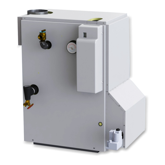
15 - CHECKING GAS INPUT RATE TO BOILER Gas input to boiler can be adjusted by removing protective Figure 19 - Boiler Right Side and Front cap on pressure regulator Figure 14, Page 22 and turning screw clockwise to increase input and counterclock- wise to decrease input. -
Page 26: Appendix A - Control Module
APPENDIX A - CONTROL MODULE A.1 Installation Environment Considerations A.3 Adjusting Settings To discourage unauthorized changing of settings, procedure WARNING to enter adjustment mode is required. If you do not follow these instructions To enter adjustment mode, press UP, DOWN, and I buttons exactly, a fire or explosion may result simultaneously for three seconds. -
Page 27: Operation
APPENDIX A - CONTROL MODULE A.5 Operation Control determines burner operation is required, module proceeds to start burner (see state codes list) Module continuously monitors boiler water temperature and and heats water in boiler until setpoint temperature is fires or shuts off burner based on this temperature data. achieved or thermostat is satisfied. -
Page 28: Boiler High Limit Temperature Controller
APPENDIX A - CONTROL MODULE A.6 Boiler High Limit Temperature Controller A.7 Troubleshooting • When water temperature reaches setpoint, controller • Following service procedures are provided as general ends heating cycle. guide. • When water temperature drops below setpoint minus •... -
Page 29: Intermittent Pilot Ignition System Verification
APPENDIX A - CONTROL MODULE Table 5 - Troubleshooting Error Codes Error Code Definition Consequence Number Flame current too low. Check for flame. Non critical alarm Flame sensed out of normal sequence (before opening or after closing gas valve). Soft lockout Gas valve relays welded. - Page 30 APPENDIX A - CONTROL MODULE STEP 3: Check spark ignition circuit. • Recheck ignition sequence as follows. Disconnect ignition cable at SPARK terminal on module. — Reconnect main valve wire. WARNING — Adjust thermostat above room temperature. — Verify ignition sequence at burner. Electrical shock hazard.
- Page 31 NOTES...
- Page 32 I M P O R T A N T In accordance with Section 325 (f) (3) of the Energy Policy and Conservation Act, this boiler is equipped with a feature that saves energy by reducing the boiler water temperature as the heating load decreases. This feature is equipped with an override which is provided primarily to permit the use of an external energy management system that serves the same function.
Need help?
Do you have a question about the Pennco 15B045FE and is the answer not in the manual?
Questions and answers