Table of Contents
Advertisement
Advertisement
Table of Contents

Related Manuals for Topcon Synergy GM-50 series


Summary of Contents for Topcon Synergy GM-50 series
- Page 1 For more information contact Synergy Positioning Systems or visit the Synergy Positioning Systems website at www.synergypositioning.co.nz All branches: Phone 0800 867 266 Email: info@synergypositioning.co.nz INSTRUCTION MANUAL Geodetic Measurement Station GM-50 series 1025821-01-A...
- Page 2 • Always keep this manual in a convenient location and read it when necessary. • This manual is protected by copyright and all rights are reserved by TOPCON CORPORATION. • Except as permitted by Copyright law, this manual may not be copied, and no part of this manual may be reproduced in any form or by any means.
- Page 3 PRECAUTIONS FOR SAFE OPERATION For the safe use of the product and prevention of injury to operators and other persons as well as prevention of property damage, items which should be observed are indicated by an exclamation point within a triangle used with WARNING and CAUTION statements in this instruction manual.
- Page 4 Power Supply Warning Do not disassemble or rebuild the battery or the battery charger, nor expose to heavy shocks or vibration. Sparking, fire, electric shock or burns could result. Do not short circuit. Heat or ignition could result. Do not place articles such as clothing on the battery charger while charging batteries.
- Page 5 Bluetooth Wireless technology Warning Do not use within the vicinity of hospitals. Malfunction of medical equipment could result. Use the instrument at a distance of at least 22 cm from anyone with a cardiac pacemaker. Otherwise, the pacemaker may be adversely affected by the electromagnetic waves produced and cease to operate as normal.
- Page 6 PRECAUTIONS Before starting work or operation, be sure to check that the instrument is functioning correctly with normal performance. Charging Battery • Be sure to charge the battery within the charging temperature range. Charging temperature range: 0 to 40°C • Use only the specified battery or the battery charger. Failures caused by using other batteries or battery chargers are out of warranty including the main unit.
- Page 7 Tribrach • Always use the tribrach provided. During a traverse observation, it is recommended to use the same type of tribrach for the target as well for accurate observations. Backing up data • Data should be backed up (transfered to an external device etc.) on a regular basis to prevent data loss. Other precautions •...
- Page 8 Contact your local dealer in advance. “25. REGULATIONS” • TOPCON CORPORATION is not liable for the content of any transmission nor any content related thereto. When communicating important data, run tests beforehand to ascertain that communication is operating normally.
- Page 9 • TOPCON CORPORATION cannot guarantee full compatibility with all Bluetooth products on the market. Exporting this product (Relating EAR) This product is equipped with the parts/units, and contains software/technology, which are subject to the EAR (Export Administration Regulations).
- Page 10 Exceptions from Responsibility • The manufacturer, or its representatives, assumes no responsibility for any damage, or loss of profits (change of data, loss of data, loss of profits, an interruption of business etc.) caused by use of the product or an unusable product.
- Page 11 LASER SAFETY INFORMATION GM is classified as the following class of Laser Product according to IEC Standard Publication 60825-1 Ed.3.0: 2014 and United States Government Code of Federal Regulation FDA CDRH 21CFR Part 1040.10 and 1040.11 (Complies with FDA performance standards for laser products except for deviations pursuant to Laser Notice No.50, dated June 24, 2007.) Device Laser class...
- Page 12 Caution • Perform checks at start of work and periodic checks and adjustments with the laser beam emitted under normal conditions. • When the instrument is not being used, turn OFF the power. • When disposing of the instrument, destroy the battery connector so that the laser beam cannot be emitted. •...
-
Page 13: Table Of Contents
Contents 1 NOMENCLATURE AND FUNCTIONS ......1-1 1.1 Nomenclature ............1-1 1.2 Display . - Page 14 6.4.5 Setting RS-232C communication with external device ....6-22 6.4.6 Selecting Communication Port........6-23 6.4.7 Confirming the Bluetooth Device Address (Only for Bluetooth function built-in model) .
- Page 15 9.4.2 PTL (Point to Line) data input ........9-11 9.5 Delete a Coordinate Data from a File .
- Page 16 23 ERROR DISPLAYS ........23-1 24 SPECIFICATIONS .
-
Page 17: Nomenclature And Functions
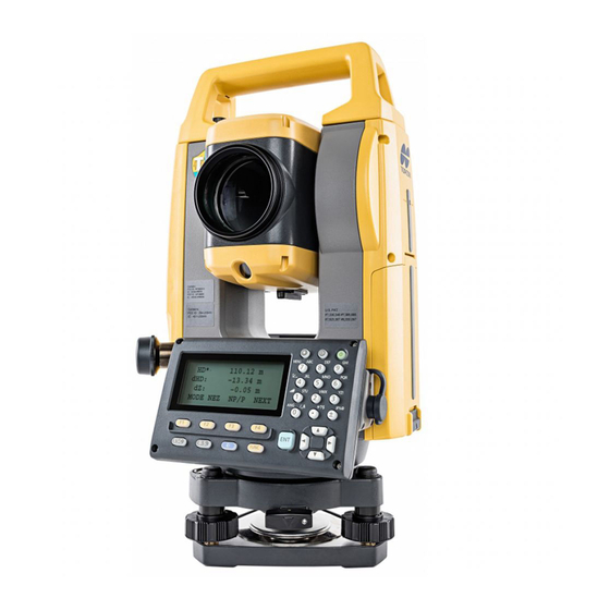
1 NOMENCLATURE AND FUNCTIONS NOMENCLATURE AND FUNCTIONS 1.1 Nomenclature Handle Instrument height mark Battery cover Operation panel Serial connector Circular level Circular level adjusting screws Base plate Levelling foot screw 10 Optical plummet focussing ring 11 Optical plummet eyepiece (10,11: Not included in instruments with laser plummet) 12 Display unit 13 Objective lens (Includes Laser-pointer... - Page 18 1 NOMENCLATURE AND FUNCTIONS Sighting collimator Use sighting collimator to aim the GM in the direction of the measurement point. Turn the instrument until the triangle in the sighting collimator is aligned with the target. A gun sight is mounted on Face 2 position of the iM-55. Align the telescope to the direction of the target in such a way that the gun sight is positioned with the target as shown below.
-
Page 19: Display
1 NOMENCLATURE AND FUNCTIONS 1.2 Display Display The display uses a graphic LCD which has 4 lines and 20 characters per line. In general, the upper three lines display measured data, and the bottom line displays the soft key function which changes with the measuring mode. -
Page 20: Operating Key
1 NOMENCLATURE AND FUNCTIONS 1.3 Operating Key Starkey Illumination key Power key Display unit Softkey selection Keys Name of Key Function Switches to Starkey mode This mode is used for each presetting or displaying as follows. 1 Contrast of the display, 2 Reticle illumination, 3 Laser pointer, 4 Tilt {} Starkey correction, 5 Set audio mode, 6 Laser Plummet... -
Page 21: Function Key (Soft Key)
1 NOMENCLATURE AND FUNCTIONS Keys Name of Key Function Turns ON/OFF of power source (Press and hold: About 1 second) Power key • In some cases, it may take longer until Power OFF. • Do not remove the battery until the display turns off. Doing so will cause data stored in the GM to be lost. - Page 22 1 NOMENCLATURE AND FUNCTIONS Distance measurement mode {F1} MEAS Start measuring {F2} MODE Sets a measuring mode, Fine/Coarse/Tracking. {F3} NP/P Switches Non-prism mode, prism mode or Sheet mode. {F4} The function of soft keys is shown on next page (P2). ↓...
-
Page 23: Starkey Mode
1 NOMENCLATURE AND FUNCTIONS 1.5 Starkey mode Press the {} key to view the instrument options. The following instrument options can be selected from the {}: 1. Adjustment the contrast of the display (0 to 15 steps) { } or { 2. - Page 24 1 NOMENCLATURE AND FUNCTIONS Adjustment the contrast (0 to 15) of the display This enable you to adjust the contrast of the display. Press the up or down arrow keys to adjust the contrast. Adjustment the reticle illumination (1 to 5) This enable you to adjust the reticle illumination.
-
Page 25: Serial Signal Rs-232C Connector
1.6 Serial signal RS-232C connector The serial signal connector is used for connecting the GM with a computer or TOPCON Data Collector, which enables the computer to receive measured data from the GM or to send preset data of horizontal angle, etc. -
Page 26: Preparation For Measurement
2 PREPARATION FOR MEASUREMENT PREPARATION FOR MEASUREMENT 2.1 Power Switch Key ON Confirm the instrument is leveled. Press the power key. Press the power key (Press and hold: About 1 second) Tilt X -3'20" 3'40" L-ON Press the {F1} (OK) key Bluetooth is under communication. -
Page 27: Battery Power Remaining Display
2 PREPARATION FOR MEASUREMENT • Avoid using any sharp implement like a needle. Malfunction of the instrument could result. • Pressing down the Reset button may result in file and folder data being lost. Reset button 2.2 Battery Power Remaining Display Battery power remaining display indicates the power condition. -
Page 28: Vertical And Horizontal Angle Tilt Correction
2 PREPARATION FOR MEASUREMENT 2.3 Vertical and Horizontal Angle Tilt Correction When the tilt sensors are activated, automatic correction of vertical and horizontal angle for mislevelment is displayed. To ensure a precise angle measurement, tilt sensors must be turned on. The display can also be used to fine level the instrument. - Page 29 2 PREPARATION FOR MEASUREMENT Setting Tilt Correction by Soft Key To enable you to select tilt ON/OFF function. setting is not memorized after power is OFF. [Example] Setting X,Y Tilt OFF Operating procedure Option Display Press {F4} key to get the function page 2. {F4} 90°10'20"...
-
Page 30: How To Enter Alphanumeric Characters
2 PREPARATION FOR MEASUREMENT 2.4 How to Enter Alphanumeric Characters This enables you to enter alphanumeric characters such as the instrument height, prism height, occupied point, backsight point etc. Alphanumeric characters key Keys Name of Key Function During numeric input, input number of the key. {0} –... - Page 31 INS.HT: 0.000 m INPUT SRCH REC OCNEZ :ST-01 INS.HT→ 0.000 m INPUT SRCH REC OCNEZ How to enter characters [Example setting] TOPCON-1 Move the arrow to enter a item using the { → or { } key. INS.HT: 0.000 m INPUT SRCH REC OCNEZ Press the {F1} (INPUT) key.
- Page 32 2 PREPARATION FOR MEASUREMENT Press the {F1} (NUM) key, again. =TOPCON The instrument switches back to numerical input mode. INS.HT: 0.000 m [ALP][SPC][CLR][ENT] Enter numbers by pressing the alphanumeric characters key. =TOPCON-1 Example: { - }, {1} key is pressed.
-
Page 33: Setting Instrument Up For Measurement
Mount the instrument to the tripod. Level and center the instrument precisely to insure the best performance. Use tripods with a tripod screw of 5/8 in. diameter and 11 threads per inch, such as the Type E TOPCON wide- frame wooden tripod. ... - Page 34 2 PREPARATION FOR MEASUREMENT PROCEDURE: Centering with the laser plummet *1: Laser plummet is available as a factory option depending on the country or the area where the instrument is purchased. 1) Set up the tripod and affix the instrument on the tripod head.
-
Page 35: Levelling
2 PREPARATION FOR MEASUREMENT evelling 2.5.2 L PROCEDURE 1) Perform the centering procedure. See Section 2.5.1 “Centering”. 2) Roughly center the bubble in the circular level by either shortening the tripod leg closest to the offcenter Tripod legs direction of the bubble or by lengthening the tripod leg adjustment farthest from the offcenter direction of the bubble. -
Page 36: Focussing And Target Sighting
2 PREPARATION FOR MEASUREMENT 6) Check again to make sure the bubble in the electric circular level is centered. If not, repeat the procedure starting from step 4. 7) Press {OK} to return to Observation mode. 2.6 FOCUSSING AND TARGET SIGHTING ... -
Page 37: Angle Measurement
3 ANGLE MEASUREMENT ANGLE MEASUREMENT 3.1 Measuring Horizontal Angle Right and Vertical Angle Make sure the mode is in Angle measurement. Operating procedure Operation Display Collimate the 1st target (A). Collimate A 90°10'20" HR: 120°30'40" ↓ 0SET HOLD HSET Set horizontal angle of target A at 0° 00' 00". {F1} H ANGLE 0 SET Press the {F1} (0 set) key and press the {F3}... -
Page 38: Measuring From The Required Horizontal Angle
3 ANGLE MEASUREMENT 3.3 Measuring from the Required Horizontal Angle 3.3.1 Setting by Holding the Angle Make sure the mode is angle measurement. Operating procedure Operation Display Set the required horizontal angle, using Display angle 90°10'20" Horizontal tangent screw 130°40'20" ↓... -
Page 39: Vertical Angle Percent Grade(%) Mode
3 ANGLE MEASUREMENT 3.4 Vertical Angle Percent Grade(%) Mode Make sure the mode is Angle measurement. Operating procedure Operation Display Press the {F4} ( ) key to get the function on page ↓ {F4} 90°10'20" 70°40'20" ↓ 0SET HOLD HSET ↓... -
Page 40: Buzzer Sounding For Horizontal Angle 90° Increments
3 ANGLE MEASUREMENT Recollimate target A using the horizontal clamp Collimate A REP-ANGLE COUNT[ 1] and tangent screw, and press the {F3} (REL)key. {F3} 45°10'00" 45°10'00" 0SET REL HOLD Recollimate target B using the horizontal clamp Collimate B REP-ANGLE COUNT[ 2] and tangent screw, and press the {F4} (HOLD) {F4} 90°20'00"... -
Page 41: Compasses (Vertical Angle)
3 ANGLE MEASUREMENT Press the {F1} (ON) key or {F2} (OFF) key to {F1} H-ANGLE BUZZER [ON] select the buzzer ON/OFF. {F2} [ON] [OFF] --- ENTER Press the {F4} (ENTER) key. {F4} 90°10'20" 170°30'20" ↓ 0SET HOLD HSET 3.7 Compasses (vertical angle) Vertical angle is displayed as shown below. -
Page 42: Distance Measurement
4 DISTANCE MEASUREMENT DISTANCE MEASUREMENT CAUTION • When using the Laser-pointer function, be sure to turn OFF the output laser after distance measurement is completed. Even if distance measurement is canceled, the Laser-pointer function is still operating and the laser beam continues to be emitted. ... -
Page 43: Setting Of The Atmospheric Correction
Refer to Section 12.2 “Setting of Atmospheric Correction Value”. 4.2 Setting of the Correction for Prism Constant Topcon’s prism constant value is 0. Set correction for prism at 0. If the prism is of another manufacture, the appropriate constant shall be set beforehand. -
Page 44: Distance Measurement (N-Time Measurement/Single Measurement)
4 DISTANCE MEASUREMENT 4.4 Distance Measurement (N-time Measurement/Single Measurement) When the number of times measurement is preset, the GM measures the distance the set number of times. The average distance will be displayed. When presetting the number of times as 1, it does not display the average distance, because of single measurement. -
Page 45: Fine Mode/Tracking Mode/Coarse Mode
4 DISTANCE MEASUREMENT 4.5 Fine Mode/Tracking Mode/Coarse Mode This setting is not memorized after power is off. Refer to Chapter 17 “SELECTING MODE” to set at the initial setting (memorized after power is off). Fine Mode : This is a normal distance measuring mode. The unit to be displayed can be changed. -
Page 46: Stake Out (S.o)
4 DISTANCE MEASUREMENT 4.6 Stake Out (S.O) The difference between the measured distance and the input stake out distance is displayed. Measured distance — Stake out distance = Displayed value In stake out operation, you can select either horizontal distance (HD), relative elevation (VD) and slope distance (SD) Operating procedure Operation... -
Page 47: Offset Measurement
4 DISTANCE MEASUREMENT 4.7 Offset Measurement There are four offset measurement modes in the Offset Measurement. Angle offset Distance offset Plane offset Column offset To show the offset measurement menu, press the [OFSET] soft key from distance or coordinate measurement mode. -
Page 48: Angle Offset
4 DISTANCE MEASUREMENT 4.7.1 Angle Offset This mode is useful when it is difficult to set up the prism directly, for example at the center of a tree. Place the prism at the same horizontal distance from the instrument as that of point A to measure. - Page 49 4 DISTANCE MEASUREMENT The horizontal distance from the instrument to the OFFSET-MEASUREMENT prism will be measured. 110°20'30" 56.789 m NEXT Collimate point A using the horizontal motion Collimate OFFSET-MEASUREMENT clamp and horizontal tangent screw. 113°30'50" 56.789 m NEXT Press the { } key, to switch the distance display OFFSET-MEASUREMENT to VD (relative elevation of point A...
-
Page 50: Distance Offset Measurement
4 DISTANCE MEASUREMENT 4.7.2 Distance Offset Measurement The measurement of a place apart from a prism is possible by inputting offset horizontal distance of front and back / right and left. Forward HD oHD sign RorLHD Prism height Prism P Instrument height Occ.Point When measuring coordinates of ground point A... - Page 51 4 DISTANCE MEASUREMENT After the measurement, the result which includes DISTANCE OFFSET offset value will be shown. 80°30'40" 10.000 m NEXT Show the relative elevation of point P0. DISTANCE OFFSET Each time pressing the { } key, horizontal 80°30'40" distance, relative elevation and slope distance are 11.789 m shown in sequence.
-
Page 52: Plane Offset Measurement
4 DISTANCE MEASUREMENT 4.7.3 Plane Offset Measurement Measuring will be taken for the place where direct measuring can not be done, for example distance or coordinate measuring for a edge of a plane. Three random prism points (P1, P2, P3) on a plane will be measured at first in the plane offset measurement to determine the measured plane. - Page 53 4 DISTANCE MEASUREMENT Measure the second and third points in the same Collimate PLANE way. N002#: {F1} MEAS NP/P --- Collimate PLANE N003#: {F1} MEAS NP/P --- The instrument calculates and displays coordinate 80°30'40" and distance value of cross point between 54.321 m collimation axis and of the plane.
-
Page 54: Column Offset Measurement
4 DISTANCE MEASUREMENT 4.7.4 Column Offset Measurement If it is possible to measure circumscription point (P1) of column directly, the distance to the center of the column (P0), coordinate and direction angle can be calculated by measured circumscription points (P2) and (P3). - Page 55 4 DISTANCE MEASUREMENT Collimate the center of the column (P1) and press Collimate COLUMN OFFSET the {F1} (MEAS) key. Center N-time measuring will start. {F1} HD* [n] << m After the measurement, angle measuring display >Measuring... of the left side (P2) will be shown. Collimate the left side of the column (P2) and Collimate COLUMN OFFSET...
-
Page 56: Coordinate Measurement
5 COORDINATE MEASUREMENT COORDINATE MEASUREMENT 5.1 Setting Coordinate Values of Occupied Point By setting the coordinates of the instrument (occupied point) based on the coordinate origin, the unknown point (prism point) coordinates based on the coordinate origin are calculated and displayed. It is possible to retain the coordinates of the occupied point after turning the power off. -
Page 57: Setting Height Of The Instrument
5 COORDINATE MEASUREMENT 5.2 Setting Height of the Instrument It is possible to retain the height of instrument after turning the power off. Refer to Chapter 17 “SELECTING MODE”. Operating procedure Operation Display Press the {F4} ( ) key from the coordinate ↓... -
Page 58: Execution Of Coordinate Measuring
5 COORDINATE MEASUREMENT 5.4 Execution of Coordinate Measuring Measure the coordinates by entering the instrument height and prism height, coordinates of unknown point will be measured directly. When setting coordinate values of occupied point, see Section 5.1 “Setting Coordinate Values of Occupied Point”... -
Page 59: Special Mode (Menu Mode)
6 SPECIAL MODE (Menu Mode) SPECIAL MODE (Menu Mode) By pressing the {MENU} key, the instrument will be in MENU mode. In this mode, special measuring, setting and adjustment are possible. Normal measurement mode {ESC} {MENU} {ESC} {F1} MENU "TOP FIELD MODE" F1:TOP FIELD ... -
Page 60: Application Measurement (Programs)
6 SPECIAL MODE (Menu Mode) 6.1 Application Measurement (PROGRAMS) 6.1.1 Remote Elevation measurement (REM) To obtain elevation of the point at which setting the target prism is not possible, place the prism at any point on the vertical line from the target then carry out REM procedure as follows. Target K Prism Prism height... - Page 61 6 SPECIAL MODE (Menu Mode) Horizontal distance (HD) between the instrument REM-1 and prism will be shown. <STEP-2> HD* 123.456 m >Measuring... REM-1 1.500 m ––– R.HT HD ––– Collimate target K. Collimate K REM-1 Vertical distance (VD) will be shown. *2),3) VD: 10.456 m –––...
- Page 62 6 SPECIAL MODE (Menu Mode) The prism position will be decided. REM-2 <STEP-2> V : 60°45'50" ––– ––– ––– Collimate ground point G. Collimate G REM-2 <STEP-2> V : 123°45'50" ––– ––– ––– Press the {F4} (SET) key. {F4} REM-2 The position of point G will be decided.
-
Page 63: Missing Line Measurement (Mlm)
6 SPECIAL MODE (Menu Mode) 6.1.2 Missing Line Measurement (MLM) Measurement for horizontal distance (dHD), slope distance (dSD), elevation (dVD) and horizontal bearing (HR) between two target prisms. It is possible to enter the coordinate value directly or calculate from coordinate data file. MLM mode has two modes. - Page 64 6 SPECIAL MODE (Menu Mode) Press the {F1} or {F2} key to select using {F2} GRID FACTOR. F1:MLM-1(A-B, A-C) [Example:F2 : DON’T USE] F2:MLM-2(A-B, B-C) Press the {F1} key. {F1} MLM-1(A-B, A-C) <STEP-1> MEAS R.HT NEZ NP/P Collimate prism A, and press the {F1} (MEAS) key. Collimate A MLM-1(A-B, A-C) Horizontal distance (HD) between the instrument...
- Page 65 6 SPECIAL MODE (Menu Mode) The horizontal distance (dHD) and relative MLM-1(A-B, A-C) elevation (dVD) between prism A and C. dHD : 234.567 m dVD : 23.456 m ––– ––– ––– To measure the distance between points A and D, repeat procedure 12 to14.
-
Page 66: Setting Z Coordinate Of Occupied Point
6 SPECIAL MODE (Menu Mode) 6.1.3 Setting Z Coordinate of Occupied Point Occupied point coordinate data and known point actual measuring data are utilized, z coordinate of occupied point is calculated and reset again. Known point data and coordinate data can use the coordinate data file. 1) Setting occupied coordinate [Example setting] Using coordinate data file. - Page 67 6 SPECIAL MODE (Menu Mode) 2) Z Coordinate Calculation from Known Point Measuring Data [Example setting] Using coordinate data file Operating procedure Operation Display After pressing {MENU} key, press {F4} (P ) key to ↓ {MENU} MENU get the menu on page 2. {F4} F1:MEMORY MGR.
- Page 68 6 SPECIAL MODE (Menu Mode) HR: 120°30'40" 12.345 m 23.456 m NEXT ––– ––– CALC Press the {F4} (CALC) key.*2) {F4} Z COORD. SETTING Z : Z coordinate 1.234 m dZ: Standard deviation dZ : 0.002 m ––– ––– Press the {F4} (SET) key. *3) {F4} BACKSIGHT Z coordinate of the occupied point will be set.
-
Page 69: Area Calculation
6 SPECIAL MODE (Menu Mode) 6.1.4 Area Calculation This mode calculate the area of a closed figure. There are two area calculation methods as follows. 1) Area Calculation from Coordinate data file 2) Area Calculation from Measured data • Area is not calculated correctly if enclosed lines cross each other. - Page 70 6 SPECIAL MODE (Menu Mode) When 3 or more points are set, the area AREA 0021 surrounded by the points is calculated and the 123.456 m.sq result will be shown. NEXT# :DATA-22 LIST UNIT NEXT *1) To set specify point, press the {F1} (PT#) key. *2) To show the list of the coordinate data in the file, press the {F2} (LIST) key.
- Page 71 6 SPECIAL MODE (Menu Mode) When 3 or more points are measured, the area AREA 0003 surrounded by the points is calculated and the 234.567 m.sq result will be shown. MEAS ––– UNIT NP/P *1) Measurement is Fine N-times measurement mode. ...
-
Page 72: Point To Line Measurement
6 SPECIAL MODE (Menu Mode) 6.1.5 Point to Line Measurement This mode is used to obtain the coordinate data with the origin point A(0,0,0) and the line AB as N axis. Place the 2 prisms at the points A and B on the line, and place the instrument at unknown point C. After measuring the 2 prisms, the coordinate data and the direction angle of the instrument will be calculated and restored. - Page 73 6 SPECIAL MODE (Menu Mode) Collimate prism P1 (Origin) and press {F1} Collimate POINT TO LINE (MEAS) key. MEAS.P1 Measuring starts. *1) {F1} HD*[n] << m >Measuring... Input display of reflector B (P2) height will be REFLECTOR HEIGHT shown. INPUT R.HT= 0.000 m --- --- [CLR] [ENT]...
-
Page 74: Setting The Grid Factor
6 SPECIAL MODE (Menu Mode) 6.2 Setting the GRID FACTOR GRID FACTOR can reset in this menu mode. For more information, refer to Section 8.1.1 “Setting the GRID FACTOR”. Grid Factor can be applied to the following application programs. It is also possible to cancel the Grid factor function by selecting "DON'T USE"... -
Page 75: Setting Illumination Of Display And Cross Hairs
6 SPECIAL MODE (Menu Mode) Press the {F3} (YES) key. {F3} GRID FACTOR ELEV.=1000 m SCALE:0.999000 --- --- [CLR] [ENT] Enter Elevation. *1) Press the {F4} (ENT) key. Enter ELEV. {F4} Enter Scale Factor in the same way. Enter Scale GRID FACTOR {F4} ELEV.:2000 m... -
Page 76: Setting Mode 1
6 SPECIAL MODE (Menu Mode) 6.4 Setting Mode 1 In this mode, the following settings are possible. 1. Setting minimum reading 2. Auto power off 3. Vertical and horizontal angle tilt correction (Tilt ON/OFF) 4. Systematic error of instrument correction 5. -
Page 77: Auto Power Off
6 SPECIAL MODE (Menu Mode) Press the {F2} key. {F2} COARSE READING F1: 1 mm [F2:10 mm ] ENTER Press the {F1} key and press the {F4} (ENTER) {F1} MINIMUM READING key. {F4} F1:ANGLE F2:COARSE To return to previous mode, press the {ESC} key. 6.4.2 Auto Power Off If no key operation is given or no process of measurement is performed for more than 30 minutes (No change exceeding 30”... -
Page 78: Vertical And Horizontal Angle Tilt Correction (Tilt On/Off)
6 SPECIAL MODE (Menu Mode) 6.4.3 Vertical and Horizontal Angle Tilt correction (Tilt ON/OFF) In case the instrument is used in an unstable situation, constant indexing of vertical and horizontal angle may be impossible. In this case, the function of tilt correction can be stopped by selecting TILT OFF. - Page 79 6 SPECIAL MODE (Menu Mode) Press the {F1} key. {F1} ERROR CORR. [OFF] The data previously set is shown. F1:ON F2:OFF ENTER Press the {F1} (ON) key or {F2} (OFF) key, and {F1} press the {F4} (ENTER) key. {F2} {F4} 6-21...
-
Page 80: Setting Rs-232C Communication With External Device
6 SPECIAL MODE (Menu Mode) 6.4.5 Setting RS-232C communication with external device you can set the parameters for RS-232C communication with external device from parameters setting menu. The following parameters can be set. Item Selecting items Baud rate 1200, 2400, 4800, 9600, 19200, 38400 Character bit (bit 7/Even, 7/Odd, 8/None length)/Parity... -
Page 81: Selecting Communication Port
6 SPECIAL MODE (Menu Mode) 6.4.6 Selecting Communication Port You can change the communication port to Bluetooth port (Bluetooth function is an optional function). Sample setting Bluetooth Operating procedure Operation Display After pressing the {MENU} key, press the {F4} {MENU} MENU ) key twice to get the menu on page 3. -
Page 82: Confirming The Bluetooth Device Address
6 SPECIAL MODE (Menu Mode) 6.4.7 Confirming the Bluetooth Device Address (Only for Bluetooth function built-in model) You can confirm the Bluetooth address Operating procedure Operation Display After pressing the {MENU} key, press the {F4} {MENU} MENU ) key twice to get the menu on page 3. ↓... -
Page 83: Humidity Input On/Off Setting
6 SPECIAL MODE (Menu Mode) 6.4.8 Humidity Input ON/OFF Setting Factory setting for humidity input is "OFF". In this case, atmospheric correction factor is calculated assuming humidity is 50%. By setting humidity input to "ON", an arbitrary value can be input for humidity. -
Page 84: Np-Trk Mode Setting
6 SPECIAL MODE (Menu Mode) 6.4.9 NP-TRK MODE Setting Set the distance mode here for performing tracking measurement, setting "Non-prism" as target type. "ROAD" is the dedicated measuring mode to sight road surface etc. obliquely to obtain rough measurement values. Normally use "STANDARD". Operating procedure Operation Display... -
Page 85: Edm Eco. Mode Setting
6 SPECIAL MODE (Menu Mode) 6.4.10EDM ECO. MODE Setting Working duration will be longer by controlling and saving power to the EDM device. • Time required to start distance measurement will be longer than usual when "EDM ECO. MODE" is set to "ON". -
Page 86: Volume Setting
6 SPECIAL MODE (Menu Mode) 6.4.11 Volume Setting Set beep volume. Volume (0 to 5, 0: beep is OFF) can also be set. Operating procedure Operation Display After pressing the {MENU} key, press the {F4} {MENU} PARAMETERS 1 ) key three times to get the menu on page 4. ↓... -
Page 87: Setting Contrast Of Display
6 SPECIAL MODE (Menu Mode) 6.5 Setting Contrast of Display Setting level for contrast of display (LCD) Operating procedure Operation Display After pressing the {MENU} key, press the {F4} {MENU} MENU ) key three times to get the menu on page 4. ↓... -
Page 88: Road
6 SPECIAL MODE (Menu Mode) 6.7 Road Road menu operation PROGRAMS F1:AREA F2:POINT TO LINE F3:ROAD P↓ Press {F3} key ROAD F1:INPUT DATA F2:SETOUT F3:INITIALIZE Input start point {F1} INPUT DATA {F1} START POINT F1:START POINT N > 0.000 F2:H ALIGNMENT 0.000 INPUT ---... -
Page 89: Inputting Start Point
6 SPECIAL MODE (Menu Mode) 6.7.1 Inputting Start Point To input the start point, carry out the following operating procedure. Operating procedure Operation Display After pressing the {MENU} key, press the {F4} {MENU} PROGRAMS ), {F2}, {F4} key to get the programs menu on ↓... -
Page 90: Inputting Road Data
6 SPECIAL MODE (Menu Mode) 6.7.2 Inputting Road Data [ROAD] is made up of four types of components: LINE, CURVE, SPIRAL and POINT. To input the required components, carry out the following operating procedure. Operating procedure Operation Display After pressing the {MENU} key, press the {F4} (P ↓... - Page 91 6 SPECIAL MODE (Menu Mode) Input CURVE data Operating procedure Operation Display F1:LINE F2:CURVE F3:SPIRAL F4:POINT To input CURVE data, press the {F2} key. *1) {F2} CURVE 0.000 0.000 --- --- [CLR] [ENT] Input RADIUS. Input CURVE Press the {ENT} key. RADIUS 100.000 m {ENT}...
- Page 92 6 SPECIAL MODE (Menu Mode) Input SPIRAL data Operating procedure Operation Display F1:LINE F2:CURVE F3:SPIRAL F4:POINT To input SPIRAL data, press the {F3} key. *1) {F3} SPIRAL 0.000 m 0.000 m --- --- [CLR] [ENT] Input RADIUS. Input SPIRAL Press the {ENT} key.
- Page 93 6 SPECIAL MODE (Menu Mode) Input POINT data Operating procedure Operation Display F1:LINE F2:CURVE F3:SPIRAL F4:POINT To input POINT data, press the {F4} key. {F4} POINT 0.000 m 0.000 m --- --- [CLR] [ENT] Input N coord. Input POINT Press the {ENT} key.
-
Page 94: Searching Data
6 SPECIAL MODE (Menu Mode) 6.7.3 Searching Data To search for input data, carry out the following operating procedure. Operating procedure Operation Display After pressing the {MENU} key, press the {F4} (P ↓ {MENU} PROGRAMS {F2}, {F4}key to get the programs menu on page 2/ {F4} F1:AREA {F2}... -
Page 95: Setting Occ And Bs
6 SPECIAL MODE (Menu Mode) 6.7.5 Setting OCC and BS To set the Occupied Point and Backsight Point, carry out the following operating procedure. Operating procedure Operation Display After pressing the {MENU} key, press the {F4} (P ↓ {MENU} PROGRAMS {F2}, {F4}key to get the programs menu on page 2/ {F4} F1:AREA... - Page 96 6 SPECIAL MODE (Menu Mode) Collimate the backsight. Collimate BACKSIGHT Backsight H(B)= 45°00’00” >Sight? [YES][NO] Press the {F3} (YES) key. {F3} <SET!> SETOUT F1:OCC&BS F2:SETOUT ROAD F3:SELECT A FILE *1) When setting the Occupied Point and Backsight Point using Resection method, select {F2} (RESECTION).
-
Page 97: Stake-Out Road
6 SPECIAL MODE (Menu Mode) 6.7.6 Stake-out Road To setout the road, carry out the following operating procedure. Operating procedure Operation Display After pressing the {MENU} key, press the {F4} (P ↓ {MENU} PROGRAMS {F2}, {F4}key to get the programs menu on page 2/ {F4} F1:AREA {F2}... -
Page 98: Selecting A File
6 SPECIAL MODE (Menu Mode) Press the {F3} (NEZ) key. {F3} 70.000 m The coordinate data is shown. 50.000 m MODE NP/P NEXT Press the {F4} (NEXT) key to set next layout point. {F4} *1) If not selecting offset, press the {ENT} key. 6.7.7 Selecting a File To set the coordinates to be used for the Occupied Point and Backsight Point, carry out the following operating procedure. -
Page 99: Data Collection
7 DATA COLLECTION DATA COLLECTION The GM is able to store the measured data into the internal memory. The internal memory is shared by the measured data files and the coordinate data files. Measured data The collected data is memorized into a files. ... - Page 100 7 DATA COLLECTION Data collect menu operation By pressing the {MENU} key, the instrument will be in MENU 1/3 mode. Press the {F2} (DATA COLLECT) key, the menu of data collect 1/2 will be shown. Normal measurement mode {ESC} {MENU} MENU F1:TOP FIELD...
-
Page 101: Preparation
7 DATA COLLECTION 7.1 Preparation 7.1.1 Selecting a File for Data Collection A file used by data collection mode must be selected at first. Select a file before beginning data collection mode because selection screen of a file is displayed. And a selection from data collection menu is possible in the mode. -
Page 102: Selecting A Coordinate File For Data Collection
7 DATA COLLECTION 7.1.2 Selecting a Coordinate File for Data Collection When coordinate data in a coordinate data file are used for occupied point or backsight point, select a coordinate file from the data collect menu 2/2 beforehand. Operating procedure Operation Display DATA COLLECT... -
Page 103: Occupied Point And Backsight Point
7 DATA COLLECTION 7.1.3 Occupied Point and Backsight Point The occupied point and direction angle in the data collect mode are linked with the occupied point and direction angle in normal coordinate measurement. It is possible to set or change the occupied point and direction angle from the data collect mode. Occupied point can be set by two setting methods as follow. - Page 104 7 DATA COLLECTION Example for setting the direction angle: The following is to memorize the data of the backsight after setting the backsight point from point number. Operating procedure Operation Display Press the {F2} (BACKSIGHT) key from the data →...
-
Page 105: Operational Procedure Of Data Collect
:PT-01 PCODE → R.HT 0.000 m INPUT SRCH MEAS ALL Enter PCODE, R.HT in the same way. *2),3) → PT-01 {F1} Enter PCODE :TOPCON PCODE R.HT 1.200 m {F4} INPUT SRCH MEAS ALL {F1} ↓ Press the {F3} (MEAS) key. -
Page 106: Searching The Recorded Data
PCODE =32 R.HT 1.200 m [ALP][SPC][CLR][ENT] Enter a register number linked with PCODE library Enter No :PT-02 and press the {F4} (ENT) key. {F4} PCODE :TOPCON (Example) → R.HT 1.200 m Register number, 32 = TOPCON INPUT SRCH MEAS ALL... -
Page 107: Entering Pcode / Id From The List Of Pcode
EDIT ––– CLR ENTER By pressing the following keys, the register 031:PCODE31 } or { number will increase or decrease. → 032:TOPCON } or { } or { }: Increasing or Decreasing one by one 033:HILTOP } or { }: By ten Increasing or Decreasing. *1) EDIT –––... -
Page 108: Data Collect Offset Measurement Mode
To set this option, refer to Chapter 17 “SELECTING MODE”. Instrument height Occ.Point Operating procedure Operation Display →PT-11 PCODE :TOPCON R.HT 1.200 m INPUT SRCH MEAS ALL Press the {F3} (MEAS) key and press the {F4}key →PT-11 {F3} to get to the next soft key page. - Page 109 } key, N,E and Z –12.345 m coordinate are shown in sequence. >OK? [YES][NO] Press the {F3} (YES) key. → PT-12 {F3} PCODE :TOPCON R.HT 1.200 m The data is recorded and the next measuring point INPUT SRCH MEAS ALL is displayed. 7-11...
-
Page 110: Distance Offset Measurement
When measuring coordinates of point A Set the instrument height only. (Set the prism height to 0). Operating procedure Operation Display →PT-11 PCODE :TOPCON R.HT 1.200 m INPUT SRCH MEAS ALL Press the {F3} (MEAS) key and press the {F4}key →PT-11 {F3} to get to the next soft key page. - Page 111 7 DATA COLLECTION Enter Forward direction offset value. *1) Enter HD :PT-11 {F4} PCODE : TOPCON R.HT 1.200 m ––– *SD NP/P Collimate the prism. Collimate P Press the {F2} or {F3} key. {F3} N*[n] <<< m Example:{F3} (NEZ) key Measuring starts.
-
Page 112: Plane Offset Measurement
Edge Target heights of P1 to P3 is set to zero automatically. Operating procedure Operation Display →PT-11 PCODE :TOPCON R.HT 1.200 m INPUT SRCH MEAS ALL Press the {F3} (MEAS) key and press the {F4}key →PT-11 {F3} to get to the next soft key page. - Page 113 NP/P --- The display changes to PT# input in the plane PLANE offset measurement. → PT-11 Input point number if necessary. PCODE :TOPCON INPUT SRCH --- MEAS Press the {F4} (MEAS) key. {F4} 80°30'40" The instrument calculates and displays coordinate 54.321 m...
-
Page 114: Column Offset Measurement
The direction angle of the center of the column is 1/2 of total direction angle of circumscription points (P2) and (P3). Example: Non-prism measurement Operating procedure Operation Display →PT-11 PCODE :TOPCON R.HT 1.200 m INPUT SRCH MEAS ALL Press the {F3} (MEAS) key and press the {F4}key →PT-11 {F3} to get to the next soft key page. -
Page 115: Nez Auto Calculation
Press the {F3} (YES) key. The display returns to → PT-12 {F3} the next point number in data collect mode. PCODE :TOPCON R.HT 1.200 m INPUT SRCH MEAS ALL 7.4 NEZ Auto Calculation As measured data is collected, coordinates are calculated and stored for traverse or topo collection. -
Page 116: Point To Line Measurement
OCC.PT Offset 7.5.1 To change to the point to line measurement Operating procedure Operation Display →PT-01 PCODE :TOPCON R.HT 1.500 m INPUT SRCH MEAS ALL Press the {F3} (MEAS) key and press the {F4}key →PT-01 {F3} to get to the next soft key page. -
Page 117: Executing A Point To Line Measurement
Display PT#PTL→PT-01 Conduct data measurement according to the same procedure as with ordinary FS/SS (ALL can also be PCODE :TOPCON selected). However, when you conduct observation in R.HT 1.500 m the angle mode, PTL data will not be displayed (only... -
Page 118: Editing Pcode Library [Pcode Input]
F1:SELECT A FILE F2:PCODE INPUT ↓ F3:CONFIG. Press the {F2} (PCODE INPUT) key from Data {F2} Collect menu 2/2. → 001:TOPCON 002:TOKYO EDIT ––– ––– By pressing the following keys, the list will 011:URAH } or { increase or decrease. -
Page 119: Setting Parameter Of Data Collect [Config.]
7 DATA COLLECTION 7.7 Setting Parameter of Data Collect [CONFIG.] In this mode, the following settings of data collect mode are possible. Setting Items Menu Selecting Item Contents Select Fine /Coarse(1) /Coarse(10) mode in distance measurement mode. The unit to be displayed is as follows. FINE / CRS(1) / F1:DIST MODE CRS(10) -
Page 120: Layout
8 LAYOUT LAYOUT LAYOUT mode has two functions which are setting of layout points and setting new points using coordinate data in the internal memory. Also, if the coordinate data is not stored in the internal memory, this can be input from keyboard. The coordinate data is loaded from PC to the internal memory via RS-232C. - Page 121 8 LAYOUT Layout menu operation By pressing the {MENU} key, the instrument will be in MENU 1/4 mode. Press the {F3} (LAYOUT) key, the menu of layout 1/2 will be shown. Normal measurement mode {ESC} {MENU} MENU F1:TOP FIELD F2:DATA COLLECT ↓...
-
Page 122: Preparation
8 LAYOUT 8.1 Preparation 8.1.1 Setting the GRID FACTOR Calculation Formula 1) Elevation Factor : The average radius of the earth Elevation Factor = R+ELEV. ELEV. : The elevation above mean sea level 2) Scale Factor Scale Factor : Scale Factor at the surveying station 3) Grid Factor ×... -
Page 123: Selecting Coordinate Data File
8 LAYOUT 8.1.2 Selecting Coordinate Data File You can execute a Layout from selected coordinate data file, also you can record New point measured data into the selected coordinate data file. The only coordinate data file existing can be selected and you can not make a new file in this mode. For more information about File, refer to Chapter 9 “MEMORY MANAGER MODE”. -
Page 124: Setting Occupied Point
8 LAYOUT 8.1.3 Setting Occupied Point Occupied point can be set by two setting methods as follow. 1) Setting from the coordinate data stored in the internal memory. 2) Direct key input of coordinate data. Example setting: Setting the occupied point from the internal coordinate data file Operating procedure Operation Display... - Page 125 8 LAYOUT Example setting: Setting Instrument point coordinates directly Operating procedure Operation Display Press the {F1} (OCC.PT INPUT) key from the {F1} OCC.PT Layout menu 1/2. PT#: INPUT LIST NEZ ENTER Press the {F3} (NEZ) key. {F3} N→ 0.000 m 0.000 m 0.000 m INPUT --- PT# ENTER...
-
Page 126: Setting Backsight Point
8 LAYOUT 8.1.4 Setting Backsight Point The following three setting methods for Backsight point can be selected. 1) Setting from the coordinate data file stored in the internal memory. 2) Direct key input of coordinate data. 3) Direct key input of setting angle. ... - Page 127 8 LAYOUT Example setting: Setting the backsight point coordinates directly Operating procedure Operation Display Press the {F2} (BACKSIGHT) key from the Layout {F2} BACKSIGHT menu 1/2. PT#: The previous data is shown. INPUT LIST NE/AZ ENT Press the {F3} (NE/AZ) key. {F3} N→...
-
Page 128: Executing A Layout
8 LAYOUT 8.2 Executing a Layout The following methods can be selected for executing a Layout: 1) Recalling points from internal memory by point number. 2) Direct key input of coordinate values. Example setting: Recalling point from internal memory. Operating procedure Operation Display LAYOUT... - Page 129 8 LAYOUT When the display value dHR, dHD and dZ are equal to 0, the layout point is established.*3) Press the {F2} (NEZ) key. {F2} 100.000 m The coordinate data is shown. 100.000 m 1.015 m MODE ANGLE NP/P NEXT Press the {F4} (NEXT) key to set next layout point.
-
Page 130: Layout Of Coordinates Of Point To Line
8 LAYOUT 8.2.1 Layout of Coordinates of Point to Line The coordinate data of point to line can be used during execution of layout. When a point name including PTL coordinates (including ‘From’ and ‘To’ data) is specified, the mode will change to PTL mode automatically. -
Page 131: Setting A New Point
8 LAYOUT 8.3 Setting a New Point New point is required for example when a layout point cannot be sighted from existing control points. 8.3.1 Side Shot Method Set up the instrument at a known point, and measure the coordinate of the new points by the side shot method Known Point B New Point... - Page 132 8 LAYOUT Press the {F4} (ENTER) key. {F4} SIDE SHOT The file will be set. PT#: INPUT SRCH ––– ENTER Press the {F1} (INPUT) key, and enter the new {F1} REFLECTOR HEIGHT point name. *4) Enter PT# INPUT Press the {F4} (ENT) key. {F4} R.HT 0.000 m...
-
Page 133: Resection Method
8 LAYOUT 8.3.2 Resection Method Set up the instrument at a new point, and calculate the coordinate of the new point using the coordinate data of maximum seven known points and the measurements made to these points. By following observation, resection is possible. •... - Page 134 8 LAYOUT Enter instrument height in the same way. Enter NO01# INS.HT PT#: {F4} INPUT LIST NEZ ENTER Enter the known point A number. *3) {F1} REFLECTOR HEIGHT Enter PT# INPUT {F4} R.HT 0.000 m --- --- [CLR] [ENT] Enter reflector height. Enter R.HT REFLECTOR HEIGHT {F4}...
- Page 135 8 LAYOUT Press the {F4} (CALC) key. *6) {F4} Standard Deviation Standard Deviation will be shown. 1.23 sec. Unit: (sec.) or (mGON) or (mMIL) ↓ ––– ––– Press the {F2} ( ) key. ↓ {F2} SD(n) : 1.23 mm Standard Deviations of each coordinate will be SD(e) : 1.23 mm shown.
- Page 136 [Example: Executing Layout Mode] Operating procedure Operation Display LAYOUT PT#: INPUT LIST NEZ ENTER While executing the LAYOUT mode, press the {F2} [TOPCON {F2} (LIST) key. → DATA-01 → The arrow( ) indicates selected data. DATA-02 VIEW SRCH ––– ENTER...
-
Page 137: Memory Manager Mode
9 MEMORY MANAGER MODE MEMORY MANAGER MODE The following items for internal memory are available in this mode. 1) FILE STATUS : Checking the number of stored data / Remaining internal memory capacity. 2) SEARCH : Searching the recorded data. 3) FILE MAINTAN. -
Page 138: Display Internal Memory Status
9 MEMORY MANAGER MODE 9.1 Display Internal Memory Status This mode is used to check the internal memory status. Operating procedure Operation Display Press the {F3} (MEMORY MGR.) key from the {F3} MEMORY MGR. menu 1/3. F1:FILE STATUS F2:SEARCH ↓ F3:FILE MAINTAN P Press the {F1} (FILE STATUS) key. -
Page 139: Searching Data
9 MEMORY MANAGER MODE 9.2 Searching Data This mode is used to search the recorded file data in the DATA COLLECT or LAYOUT mode. The following 3 search methods in each type of files can be selected. First data search Last data search Point number search (MEAS.DATA, COORD.DATA) Number search (PCODE LIB.) - Page 140 9 MEMORY MANAGER MODE Press the {F4} ( ) key to scroll data for selected ↓ {F4} TOP-104 point. PCODE R.HT 1.200 m ↓ EDIT Refer to Section 2.6 "How to enter alphanumeric characters". *2) To show the file list, press the {F2} (LIST) key. ...
-
Page 141: Coordinate Data Searching
9 MEMORY MANAGER MODE 9.2.2 Coordinate Data Searching Example searching: Point number searching Operating procedure Operation Display Press the {F3} (MEMORY MGR.) key from the {F3} MEMORY MGR. menu 1/3. F1:FILE STATUS F2:SEARCH ↓ F3:FILE MAINTAN Press the {F2} (SEARCH) key. {F2} SEARCH F1:MEAS. -
Page 142: Pcode Library Searching
9 MEMORY MANAGER MODE 9.2.3 PCODE LIBRARY Searching Example searching: Number searching Operating procedure Operation Display Press the {F3} (MEMORY MGR.) key from the {F3} MEMORY MGR. menu 1/3. F1:FILE STATUS F2:SEARCH ↓ F3:FILE MAINTAN Press the {F2} (SEARCH) key. {F2} SEARCH F1:MEAS. -
Page 143: File Maintenance
9 MEMORY MANAGER MODE 9.3 File Maintenance In this mode, the following items are available. Renaming file name / Searching data in a file / Deleting files FILE MAINTAN. menu MEMORY MGR. F1:FILE STATUS F2:SEARCH ↓ F3:FILE MAINTAN. P {ESC} {F3} @AMIDAT... -
Page 144: Rename A File
9 MEMORY MANAGER MODE 9.3.1 Rename a File An existing file in internal memory can be renamed. Operating procedure Operation Display Press the {F3} (FILE MAINTAN.) key from the {F3} Memory manager menu 1/3. →MEASD1 /M0123 COORD1 /C0056 SRCH ––– Select a file by pressing { } or { } key. -
Page 145: Deleting A File
9 MEMORY MANAGER MODE 9.3.3 Deleting a File This mode erases a file from internal memory. Only one file can be erased at a time. Operating procedure Operation Display Press the {F3} (FILE MAINTAN.) key from the {F3} Memory manager menu 1/3. →MEASD1 /M0123 COORD1... -
Page 146: Coordinate Data Direct Key Input
{F4} PCODE:_________ INPUT LIST ––– ENTER Enter PCODE and press the {F4} (ENTER). {F1} COORD. DATA INPUT Enter PCODE PT#:TOPCON-102 Next input display is shown, point number (PT#) is {F4} automatically incremented. INPUT ––– ––– ENTER Refer to Section 2.4 “How to Enter Alphanumeric Characters”. -
Page 147: Ptl (Point To Line) Data Input
INPUT LIST ––– ENTER E: Elevation Enter PCODE, FROM and TO data and press the {F1} COORD. DATA INPUT {F4} (ENTER).*2) Enter PCODE PT#:TOPCON-102 {F4} Next input display is shown, point number (PT#) is INPUT ––– ––– ENTER automatically incremented. ... -
Page 148: Delete A Coordinate Data From A File
9 MEMORY MANAGER MODE 9.5 Delete a Coordinate Data from a File Coordinate data in a file can be erased. Operating procedure Operation Display Press the {F3} (MEMORY MGR.) key from the {F3} MEMORY MGR. menu 1/3. F1:FILE STATUS F2:SEARCH ↓... -
Page 149: Editing Pcode Library
↓ {F4} MEMORY MGR. F1:COORD. INPUT F2:DELETE COORD. ↓ F3:PCODE INPUT Press the {F3} (PCODE INPUT) key. {F3} →001:TOPCON 002:TOKYO EDIT ––– ––– By pressing the following keys, the list will 011:URAH } or { increase or decrease. → 012:AMIDAT... -
Page 150: Data Communications
9 MEMORY MANAGER MODE 9.7 Data Communications You can send a data file stored in the internal memory to a computer directly. Also, you can directly load a coordinate data file and PCODE Library data to the internal memory from the computer. 9.7.1 Sending Data Example: Sending a Measured data file Operating procedure... - Page 151 9 MEMORY MANAGER MODE Press the {F3} (YES) key.*5) {F3} SEND MEAS. DATA The sending starts. The display will return to menu. < Sending Data!> STOP *1) Only for Bluetooth function built-in model Refer to Section 2.4 “How to Enter Alphanumeric Characters”. *3) To scroll the data, press the { } or { } key.
-
Page 152: Loading Data
9 MEMORY MANAGER MODE 9.7.2 Loading Data Coordinate data files and PCODE Library data can be loaded from PC. Example: Loading a coordinate data file (from PC) Operating procedure Operation Display Press the {F3} (MEMORY MGR.) key from the {F3} MEMORY MGR. -
Page 153: Setting Parameter Of Data Communications
9 MEMORY MANAGER MODE 9.7.3 Setting Parameter of Data Communications Items of the Parameter Item Selecting Item Contents Setting Protocol [ACK/NAK], F1: Protocol [ONE WAY] [ACK/NAK] or [ONE WAY] communication Setting transfer speed 1200, 2400, 4800, F2: Baud rate 9600, 19200, 38400 1200/2400/4800/9600/19200/38400 baud Setting data length and parity. -
Page 154: Confirming The Parameters For Bluetooth Communication
9 MEMORY MANAGER MODE Press the {F4} (ENTER) key. {F4} COMM. PARAMETERS 1/2 F1:PROTOCOL F2:BAUD RATE ↓ F3:CHAR./PARITY *1) Only for Bluetooth function built-in model *2) To cancel setting, press the {ESC} key. 9.7.4 Confirming the parameters for Bluetooth communication (Only for Bluetooth function built-in model) The communication parameters for the Bluetooth are fixed as follows. -
Page 155: Initialization
9 MEMORY MANAGER MODE 9.8 Initialization This mode is used to initialize the internal memory. Following data can be initialized. FILE DATA : All files of measuring data and coordinate data PCODE DATA : PCODE LIST ALL DATA : FILE DATA and PCODE DATA ... -
Page 156: Set Audio Mode
10 SET AUDIO MODE SET AUDIO MODE The light acceptance quantity level for the EDM (SIGNAL), the atmospheric correction value (PPM), and prism constant correction value of each target are displayed in this mode. When reflected light from the prism is received a buzzer sounds. This function is good for easy collimation when the target is difficult to find. -
Page 157: Setting The Prism Constant Value
11 SETTING THE PRISM CONSTANT VALUE SETTING THE PRISM CONSTANT VALUE The prism constant value of Topcon is set to zero. When using prisms other than Topcon’s, it is necessary to set the prism constant correction value of that specific prism. -
Page 158: Setting Atmospheric Correction
12 SETTING ATMOSPHERIC CORRECTION SETTING ATMOSPHERIC CORRECTION The velocity of the light beam used for measurement varies according atmospheric conditions such as temperature and air pressure. Set the atmospheric correction factor when you wish to take this influence into account when measuring. The GM is designed so that the correction factor is 0 ppm at an air pressure of 1013.25hPa, a temperature of 15°C, and a humidity of 50%. -
Page 159: Setting Of Atmospheric Correction Value
12 SETTING ATMOSPHERIC CORRECTION Humidity h Humidity h • If the weather correction is not required, set the ppm value to 0. 12.2 Setting of Atmospheric Correction Value How to set temperature, pressure and humidity value directly Measure the temperature, pressure and humidity surrounding the instrument beforehand. ... - Page 160 12 SETTING ATMOSPHERIC CORRECTION Input temperature, pressure, and humidity Enter Temp. TEMP. : 26.0 °C values.*1) Enter Pres. PRES. : 1017.0 hPa Mode returns to Set Audio mode. HUMID.: 45.0 INPUT ––– ––– ENTER Refer to Section 2.4 “How to Enter Alphanumeric Characters”. ...
-
Page 161: Correction For Refraction And Earth Curvature
13 CORRECTION FOR REFRACTION AND EARTH CURVATURE CORRECTION FOR REFRACTION AND EARTH CURVATURE The instrument measures distance, taking into account correction for refraction and earth curvature. 13.1 Distance Calculation Formula Distance Calculation Formula; with correction for refraction and earth curvature taken into account. Follow the Formula below for converting horizontal and vertical distances. -
Page 162: Power Source And Charging
14 POWER SOURCE AND CHARGING POWER SOURCE AND CHARGING 14.1 Battery Charging Be sure to charge the battery fully before using it for the first time or after not using it for long periods. • The charger will become rather hot during use. This is normal. •... -
Page 163: Installing/Removing The Battery
14 POWER SOURCE AND CHARGING 14.2 Installing/Removing the Battery Mount the charged battery. Type of power source: see Chapter 21 “BATTERY SYSTEM” . • Use the provided battery BDC46C/BDC70 (optional accessory) for this instrument. • When removing the battery, turn the power off. •... -
Page 164: Using Usb Flash Drive
15 USING USB FLASH DRIVE USING USB FLASH DRIVE It is possible to read in/output data from/to a USB flash drive. • When using a USB flash drive, data is stored in the root folder. You cannot read/write data from/to subfolders. - Page 165 15 USING USB FLASH DRIVE PROCEDURE Removing USB Flash Drive Remove the USB flash drive from the USB port. Close the external interface hatch until a click is heard. • It is recommended that you remove the USB flash drive after you finish inputting/outputting data and then return to the MEMORY MGR.
-
Page 166: Detach/Attach Of Tribrach
16 DETACH/ATTACH OF TRIBRACH DETACH/ATTACH OF TRIBRACH The instrument is easily detached or attached to the tribrach, with a tribrach locking lever loosened or tightened for this purpose. Detachment Loosen the tribrach locking lever, by revolving it 180° or 200 gon in the counterclockwise direction (which will point the triangle mark upwards). -
Page 167: Selecting Mode
17 SELECTING MODE SELECTING MODE 17.1 Items of the Selecting Mode The following modes are available. Menu Items Selecting item Display TEMP. & °C/°F Select the unit of temperature for atmospheric UNIT SET PRES. hPa / mmHg /inHg correction. Select the unit of air pressure for atmospheric correction. - Page 168 When the instrument is turned ON, the screen to request the password will appear. *2 *1 Applicable only to the instruments with security function *2 If you forget a password, the instrument needs repair to cancel the password. Please contact Topcon or your local Topcon dealer. 17-2...
-
Page 169: How To Set Selecting Mode
17 SELECTING MODE 17.2 How to Set Selecting Mode <Example>: Setting unit in hPa, °F, NEZ MEMORY:ON Operating procedure Operation Display After pressing the {MENU} key, press the {F4} {MENU} MENU ) key twice to get the menu on page 3. ↓... - Page 170 17 SELECTING MODE Press {F1} key. {F1} NEZ MEMORY [OFF] [ON] [OFF] ––– ENTER Press {F1} (ON) key, and press {F4} (ENTER) {F1} OTHERS SET key. {F4} F1:NEZ MEMORY Returns to OTHERS SET menu. F2:REC TYPE ↓ F3:CR,LF 17-4...
-
Page 171: Checks And Adjustments
18 CHECKS AND ADJUSTMENTS CHECKS AND ADJUSTMENTS A GM is a precision instrument that requires fine adjustments. It must be inspected and adjusted before use so that it always performs accurate measurements. • Always perform checking and adjustment in the proper sequence beginning from Section 18.1 “Circular Level”... -
Page 172: Adjustment Of Vertical Angle 0 Datum
18 CHECKS AND ADJUSTMENTS 18.2 Adjustment of Vertical Angle 0 Datum If when measuring the vertical angle of target A at telescope position normal (direct) and reverse settings, the amount of normal and reverse measurements combined is other than 360° (ZENITH-0), half of the difference from 360°... -
Page 173: Adjustment Of Compensation Systematic Error Of Instrument
18 CHECKS AND ADJUSTMENTS 18.3 Adjustment of Compensation Systematic Error of Instrument 1 Vertical axis error 2 Collimation axis error 3 Vertical angle 0 datum error Correction constants for the above errors are calculated and stored in the instrument by the following procedure, and then measurement values are corrected using the stored constants. - Page 174 18 CHECKS AND ADJUSTMENTS Press the {F4} (SET) key. {F4} Repeat the procedures in step so that the COMPLETE count of measured times matches to the one in FACE (1). *2) To show the constant list of systematic error of ADJUSTMENT MODE instrument F1:V ANGLE 0 POINT...
-
Page 175: Reticle
18 CHECKS AND ADJUSTMENTS 18.4 Reticle With this option you can check the perpendicularity of the reticle and the horizontal/vertical positions of reticle lines. Check 1: Perpendicularity of the reticle to the horizontal axis 1) Carefully level the instrument. 2) Align a clearly visible target (the edge of a roof for example) on point A of the reticle line. -
Page 176: Optical Plummet
18 CHECKS AND ADJUSTMENTS 5) Do the calculations: A2-A1 and B2+B1 If A2-A1 is within 180°±20″and B2(B1 is within 360°±40″, adjustment is unnecessary. Example: A2-A1 (Horizontal angle) =198° 34' 20"- 18° 34' 00" =180° 00' 20" B2-B1 (Vertical angle) =269° 30' 00" + 90° 30' 20" =360°... -
Page 177: Additive Distance Constant
18 CHECKS AND ADJUSTMENTS 4) Remove the optical plummet reticle cover. Cover Adjusting screw 5) Turn the 4 adjusting screws of the optical plummet to adjust the remaining half of the deviation using hexagonal wrench (1.3 mm) as shown below. When the survey point is on the lower (upper) part of the illustration: Loosen the upper (lower) adjusting screw slightly, and... -
Page 178: Checking And Adjusting Of Laser Plummet*1
18 CHECKS AND ADJUSTMENTS Checking 1) Find an area of flat ground where two points 100 m apart can be selected. Set up the Instrument at point A and the reflective prism at point B. Establish a point C half way between points A and 2) Precisely measure the horizontal distance between point A and point B 10 times and calculate the average value. - Page 179 18 CHECKS AND ADJUSTMENTS Adjusting 1) Turn the laser plummet adjustment cap anticlockwise and remove. 2) Emit the laser plummet beam. 3) Note the current position (x) of the laser beam. 4) Turn the upper part of the instrument horizontally through 180°...
- Page 180 18 CHECKS AND ADJUSTMENTS 7) When the laser beam is in the right (left) part of Fig. B the left (right) adjustment is made as follows: a. Insert a hexagon key wrench into both the left and right screws. b. Slightly loosen the right (left) screw and tighten the left (right) screw.
-
Page 181: Top Field Mode
19 TOP FIELD MODE TOP FIELD MODE 19.1 MAIN MENU (Major Functions) MENU 1.JOB [ 1.JOB••• {F1} {F1} F1:TOP FIELD 2.SETTING Performs process F2:DATA COLLECT 3.GO TO WORK related to JOB ↓ ↓ F3:LAYOUT management 2.SETTING••• {F2} Configures setting for distance unit and mode {F4} 3.GO TO WORK•••... -
Page 182: To Select Existing Job
19 TOP FIELD MODE 19.2.2To Select Existing Job Operating procedure Operation Display Select {F1} (TOP FIELD) from the menu. {MENU} 1.JOB [ {F1} 2.SETTING 3.GO TO WORK ↓ Select {F1} (JOB). {F1} 1.OPEN JOB FILE 2.CREATE NEW JOB 3.NO JOB FILE ↓... -
Page 183: When Job Is Not To Be Used
19 TOP FIELD MODE Select an existing job name with {F1} or {F2} Enter/ SELECT JOB TO DEL (Arrow) key, or enter a job name. Select job [JOB1_ name ↑ ↓ Press {ENT} key. {ENT} SELECT JOB TO DEL [JOB1_ >OK ? [YES][NO] Pressing {F3} (YES) key will delete the job file. -
Page 184: Go To Work
19 TOP FIELD MODE Select {F1} to {F3} to set the unit of distance. Select 1.N,E,Z {F1} ~ {F3} 2.E,N,Z {F1} (US FEET-10THE): Display in feet 3.X,Y,Z {F2} (US FEET-INCHES): Display in feet and inches {F3} (METERS): Display in meters Select {F1} to {F3} to set the display sequence of Select 1.FINE... - Page 185 19 TOP FIELD MODE Select {F1} (SELECT INST PT). {F1} ENTER INST PT PT#: ↑ ↓ Select an existing coordinate point with {F1} or Enter/ ENTER INST PT {F2} (Arrow) key, or directly enter a coordinate Select PT# PT#: [OCC-PT point.
- Page 186 19 TOP FIELD MODE Enter occupied point coordinates (N, E, Z). Enter occu- N [0.000 pied point E [0.000 coordinate Z [0.000 Set with {ENT} key. {ENT} ENTER INST HT INST HT =0.000_ Enter an instrument height. Enter ENTER INST HT instrument INST HT height...
- Page 187 19 TOP FIELD MODE Enter a reflector height. Enter ENTER TARGET HT reflector HT OF ROD height =1.500_ Set with {ENT} key. {ENT} ENTER TARGET PT# 1/2 PT#: ↑ ↓ Select the coordinate point of a collimate point Enter/ ENTER TARGET PT# 1/2 with {F1} or {F2} (Arrow) key, or enter the Select PT# PT#:...
- Page 188 19 TOP FIELD MODE Set with {ENT} key. {ENT} POINT X SET! ORIENTATION SET! When you press {F1} (OK), an occupied point and {F1} 1.INST SETUP backsight will be set and the procedure will be 2.LAYOUT completed. 3.TOPO The backsight is set up based on the previously collimated prism position.
- Page 189 19 TOP FIELD MODE To set backsight After completing the occupied point setting, the display for backsight setting will be displayed. Setting from existing coordinate data Operating procedure Operation Display When the occupied point setting is completed, 1.SELECT BS PT this menu screen will be displayed.
- Page 190 19 TOP FIELD MODE Setting by entering the coordinate data of a collimate point directly Operating procedure Operation Display After the occupied point setting is completed, 1.SELECT BS PT this menu will be displayed. 2.CREATE BS PT 3.BS DIRECTION Select {F2} (CREATE BS PT).
- Page 191 19 TOP FIELD MODE Using an existing horizontal angle and saving the coordinate data of the collimate point Operating procedure Operation Display After the occupied point setting is completed, 1.SELECT BS PT this menu will be displayed. 2.CREATE BS PT 3.BS DIRECTION Select {F2} (CREATE BS PT).
- Page 192 19 TOP FIELD MODE Select {F3} (BS DIRECTION). {F3} ENTER BS ANGLE BS AN[_ DDD.MMSS 0SET Enter a backsight directly. Enter ENTER BS ANGLE Pressing {F1} (0SET) will enter 0. backsight BS AN[0.0000_ DDD.MMSS 0SET Set with {ENT} key. {ENT} SIGHT BS TARGET >OK ? [YES][NO]...
-
Page 193: To Layout
19 TOP FIELD MODE 19.4.2To Layout Operating procedure Operation Display 1.INST SETUP 2.LAYOUT 3.TOPO Select {F2} (LAYOUT). {F2} ENTER TARGET HT HT OF ROD =0.000_ Enter a reflector height. Enter ENTER TARGET HT reflector HT OF ROD height =1.500_ Set with {ENT} key. {ENT} ENTER LAYOUT POINT# PT#:... -
Page 194: To Conduct Ordinary Measurement And To Record Coordinates
19 TOP FIELD MODE Pressing {F2} (NEZ) key will display coordinate {F2} 1.250 m data. 2.500 m Line 1: N coordinate (E coordinate) 0.010 m Line 2: E coordinate (N coordinate) NEXT Line 3: Z coordinate Pressing {F2} (dHA) will return to the angle difference display. - Page 195 19 TOP FIELD MODE Pressing {F2} (SD) key will switch the distance {F2} 60°00'00" display to the SD display. 120°00'00" 11.547 m Pressing {F3} (NEZ) key will switch to the {F3} -5.000 m coordinate display. 8.660 m 5.774 m Pressing {F3} (A/D) key will switch to the {F3} 60°00'00"...
-
Page 196: Data Manager
19 TOP FIELD MODE 19.5 DATA MANAGER The following operations can be performed with DATA MANAGER. ••••••ADD POINT 1) Adding coordinate data ••••••DELETE POINT 2) Deleting coordinate data ••••••VIEW POINT 3) Viewing coordinate data ••••••EDIT POINT 4) Editing coordinate data ••••••DATA TRANSFER 5) Transferring coordinate data 4.DATA MANAGER... - Page 197 19 TOP FIELD MODE Enter N/E/Z coordinates. Enter NEZ N [0.000 Coordinate E [0.000 Data Z [0.000_ Set with {ENT} key. {ENT} PT#: [P01 The coordinate point and the job name will be STORED! displayed and the procedure will be completed. [JOB1 1.COORDINATES 2.REFLINE...
- Page 198 19 TOP FIELD MODE Acquire coordinate data for Reference "REF2" in Enter/ ENTER REF2 the same manner. Select PT# PT#: [P02_ DESC: ↑ ↓ {ENT} ENTER DISTANCE Enter the distance (DISTANCE) from reference Enter ENTER DISTANCE "REF1" to the direction of "REF2". DISTANCE = 10.000_ Set with {ENT} key.
- Page 199 19 TOP FIELD MODE The calculated value will be displayed for the {ENT} PT#: [P03 coordinate data. Set with {ENT} key. STORED! [JOB 1 1.COORDINATES 2.REFLINE 3.TAPE TAPE END PT# OFFSET ADD POINT START PT# Operating procedure Operation Display 1.COORDINATES 2.REFLINE...
-
Page 200: To Delete Coordinate Data
19 TOP FIELD MODE Enter the horizontal distance (OFFSET) from Enter ENTER FROM END PT# "END" point. OFFSET, To select directions, press {F1} (LEFT) to move to {F1} or = 5.000_ the left and {F2} (RIGHT) to the right. {F2} LEFT RIGHT Set with {ENT} key. -
Page 201: To View Coordinate Data
19 TOP FIELD MODE Select a coordinate point to delete with {F1} or Enter/ ENTER PT TO DEL {F2} (Arrow) key, or enter a coordinate point Select PT# PT#: [P01_ directly. DESC: ↑ ↓ Set with {ENT} key. {ENT} ENTER PT TO DEL PT#: [P01 DESC:... -
Page 202: To Edit Coordinate Data
19 TOP FIELD MODE 19.5.4To Edit Coordinate Data Operating procedure Operation Display Only entered coordinate data (design data) can 4.EDIT POINT be edited. 5.DATA TRANSFER ↑ Select {F1} (EDIT POINT). {F1} DESIGN PT PT#: [P01 DESC: [POINT ↑ ↓ EDIT Select a coordinate point to edit with {F1} or {F2} {F1} or... -
Page 203: To Transfer Coordinate Data
19 TOP FIELD MODE 19.5.5To Transfer Coordinate Data Operating procedure Operation Display 4.EDIT POINT 5.DATA TRANSFER ↑ Select {F2} (DATA TRANSFER). {F2} DATA TRANSFER Data transfer corresponds to the following two F1:GTS FORMAT types of transmission formats: F2:SSS FORMAT F1: GTS FORMAT F2: SSS FORMAT ... - Page 204 19 TOP FIELD MODE Receiving coordinate data Operating procedure Operation Display DATA TRANSFER F1:GTS FORMAT F2:SSS FORMAT Select the transmission format used for receiving {F1} DATA TRANSFER data. F1:SEND DATA {F2} F2:LOAD DATA F1: GTS FORMAT F3:COMM. PARAMETERS F2: SSS FORMAT Select {F2} (LOAD DATA).
-
Page 205: Special Accessories
20 SPECIAL ACCESSORIES SPECIAL ACCESSORIES The following are optional accessories which are sold separately from the GM. Target and power supply optional accessories: see Section 21 “BATTERY SYSTEM”. and 22 “PRISM SYSTEM”. Plumb bob The plumb bob can be used to set up and center the instrument on days when there is little wind. - Page 206 20 SPECIAL ACCESSORIES Power cable/Interface cable (optional accessory) Connect the instrument to a host computer using the following cables. Cable Notes DOC210 Pin number and signal level : RS232C compatible D-Sub connector : 9 pins (female) 20-2...
-
Page 207: Battery System
21 BATTERY SYSTEM BATTERY SYSTEM Operate your instrument with the following combinations of power equipment. • For details about batteries and chargers, refer to each dedicated manual. • Never use any combination other than those indicated below. If you do, the instrument could be damaged. -
Page 208: Prism System
22 PRISM SYSTEM PRISM SYSTEM Select a prism or a target depending on your purpose. The following are all special accessories (sold separately). • When using a reflecting prism equipped with a target for distance and angle measurements, be sure to direct the reflective prism correctly and sight the center of the prism target accurately. - Page 209 22 PRISM SYSTEM Prism-2 Prism constant correction values differ depending on the prism holders to use. Check the own value which is written on the holder in many cases. Prism constant correction value : 0 mm/-30 mm Aperture : 58 mm ...
- Page 210 23 ERROR DISPLAYS ERROR DISPLAYS The following is a list of the error messages displayed by the instrument and the meaning of each message. • There is a possibility that an unexpected error occasionally occurs when using an old battery. In such a case, exchange it for a new battery, and please check the operation of the instrument.
- Page 211 23 ERROR DISPLAYS FULL When making a file, 99 files already exist. If necessary, send or delete files. FILES LIMIT Limit of input data exceeded. Input again. OVER MEMORY Any abnormality occurs with internal memory. Initialize the internal memory. ERROR MEMORY Shortage of capacity of the internal memory.
- Page 212 24 SPECIFICATIONS SPECIFICATIONS Except where stated, the following specifications apply to all models of GM Series. Telescope Length 171 mm Aperture 45 mm (EDM:48 mm) Magnification Image Erect Resolving power 2.5" Field of view 1°30' Minimum focus 1.3 m Reticle illumination 5 brightness levels Angle measurement Horizontal and Vertical circles type...
- Page 213 24 SPECIFICATIONS Reflectorless (White) : 0.3 to 500 m (1,640 ft) *2 *7 *8 (0.3 to 500 m (1,640 ft) Prism (tracking) 1.3 to 1,000 m (3,280 ft) Reflective sheet target (tracking) 1.3 to 350 m (1,140 ft) 1.3 to 210 m (680 ft) Reflectorless (White) (tracking, road): 0.3 to 300 m (980 ft) Minimum display Fine measurement:...
- Page 214 24 SPECIFICATIONS Measurement at 50 to 60°C (122 to 140°F) (Standard Model) Figures when using Kodak Gray Card White side (reflection factor 90%), brightness level is less than 5,000 lx and the laser beam strikes orthogonally the White side. Figures when using Kodak Gray Card White side (reflection factor 90%), brightness level is less than 500 lx and the laser beam strikes orthogonally the White side.
- Page 215 24 SPECIFICATIONS Size: 94 (W) X 102 (D) X 36 (H) mm Weight: about 170 g General Display unit LCD graphic display, 192 dots X 80 dots Backlight: On/Off (selectable) Operation panel (keyboard) 28 keys (soft function, operations, power on, light) with illuminator Sensitivity of levels Circular level:...
- Page 216 25 REGULATIONS REGULATIONS Region/ Directives/ Labels/Declarations Country Regulations FCC Compliance U.S.A. FCC-Class B WARNING: Changes or modifications to this unit not expressly approved by the party responsible for compliance could void the user's authority to operate the equipment. Note: This equipment has been tested and found to comply with limits for a Class B digital device, pursuant to Part 15 of the FCC Rules.
- Page 217 25 REGULATIONS Region/ Directives/ Labels/Declarations Country Regulations California and Recycling NY, U.S.A. Batteries Canada ICES-Class B This class B digital apparatus meets all requirements of Canadian interference-Causing Equipment Regulations. Cet appareil numérique de la class B respecte toutes les exigences du Réglement sur le matérique brouilleur du Canada.
- Page 218 This product complies with the electromagnetic environmental testing of industrial locations. Hereby, TOPCON CORPORATION declares that the radio equipment type of this product is in compliance with Directive 2014/53/EU. EU declaration of conformity is available depending on your request.
- Page 219 25 REGULATIONS Region/ Directives/ Labels/Declarations Country Regulations China Chinese Environmental Directive Taiwan 25-4...
- Page 220 Please see the attached address list or the following website for contact addresses. GLOBAL GATEWAY http://global.topcon.com/ ©2018 TOPCON CORPORATION ALL RIGHTS RESERVED...
Need help?
Do you have a question about the Synergy GM-50 series and is the answer not in the manual?
Questions and answers