
Related Manuals for Samsung SNOW-AAE


Summary of Contents for Samsung SNOW-AAE
- Page 1 S -Box Installation Manual SNOW -AAE Model Name: LED Signage Box for IWA Series Cabinet Model Code: SBB - SNOWAAE/** Ver 1.0 The Wall R&D Lab...
-
Page 2: Revision History
Revision History Version Date (Y/M/D) Description 2021/05/19 New Release The Wall R&D Lab... - Page 3 1. Product’s Description Contents 2. SBOX install precautions 3. SBOX installation and connection 4. Setting and guide The Wall R&D Lab...
-
Page 4: Product's Description
1. Product’s Description The Wall R&D Lab... - Page 5 1. Product’s Description MODEL SBB -SNOWAAE PANEL Input HDMI1~4 In, DP In, RS232(for Service ), External IR/Eco , External BT/WiFi, RJ45 LAN, USB, Power 24V Output DVI (for sevice), AOC 8EA (to Cabinet), HDBT (for External BT/WiFi), SPDIF [Default] 3840*2160@60 Hz Input [Max] 7680 x 4320 @ 60 Hz (DP, HDMI 4), 3840 x 2160 @ 60 Hz (HDMI 1~3) Resolution...
- Page 6 1. Product’s Description Model SBB -SNOWAAE SBB -SNOWJMU Image Support Model IWA, IFA, IFR/IER/IEA IFA, IFR/IER/IEA Oscar - P Kant-M2e SCALER SE19HM SE18S FPGA KU060, K325T KU085 Screen Resolution Input HDMI(4), DP(1), USB(2 ) HDMI(3), DP(1), USB(2 ) Connectivity Audio Out Optical (2CH, PCM only) Optical (2CH, PCM only) Video Out...
- Page 7 1. Product’s Description Detail size S-Box Width (A, mm) 440.0 75.6 Length (B, mm) 348.9 210.6 Depth (C, mm) 60.5 23.3 Weight (kg) [I/G] [S-Box] The Wall R&D Lab...
- Page 8 1. Product’s Description S -Box size SNOWAAE Set Size [WxDxH][mm] 440.0 x 348.9 x 60.5 (without Foot) Weight 4.2kg Mechanical Exploded View Description Part Code ASSY COVER-TOP BN96-53723A PCB MAIN-SNOW-AAE_OSCAR-P BN94-17037A PCB MISC-SNOWAAE_24VDC_SUB BN94-17039A PCB MAIN SUBCON-SNOW-AAE_FPGA BN94-17039A ASSY BOARD P-SUB BN96-54021A ASSY BRACKET-PCB...
-
Page 9: Mechanical Exploded View
1. Product’s Description Interface Gender size Set Size [WxDxH][mm] 75.6 x 210.6 x 23.3 (without Foot) Weight 0.4kg Mechanical Exploded View Description Part Code ASSY COVER-TOP BN96-53720A ASSY PCB MISC BN94-17035A ASSY BRACKET-PCB BN96-53722A SCREW-MACHINE 6001-003010 SCREW-MACHINE 6001-003016 The Wall R&D Lab... - Page 10 Product’s Description Bridge Box size SNOWAAE Set Size [WxDxH][mm] 53.2 x 98.2 x 22.5 (without Foot) Weight 0.1kg Mechanical Exploded View Description Part Code COVER-TOP BN96-49701A BN41-02701A BRACKET-PCB BN96-49702A SCREW-TAPTYPE 6001-003016 SCREW-TAPTYPE 6001-002755 The Wall R&D Lab...
- Page 11 Product’s Description Group Group Group Group Group Group Group Group Default (4K) Optional kit Optional kit Optional kit 【 optional kit for sale Optional kit(1PKG) Z-Order N-Order SBOX Group Group Group Group Module(Tx) Module(Rx) OCM Cable Don’t need a kit Add 3ea kits for 8K (default) Group...
- Page 12 2. S -Box install precautions The Wall R&D Lab...
- Page 13 S -Box install precautions Check list before install ① Open the box after remove the tape on the box POWER CODE 3903-001117 Check the items on the Top-cushion( IG, Bridge box, accessories / refer below image) 3903-001118 KOREA 3903-001074 Remove Top-cushion and then take out SBOX from PE BAG CHINA 3903-001075...
- Page 14 3. S -BOX installation and connection The Wall R&D Lab...
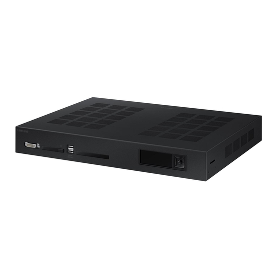
- Page 15 3. S -BOX installation and connection SNOW -AAE Front/RearSide - Front Info LCD Jog Key DVI-OUT IR Rx / Power Btn USB 2.0 IR Tx (monitoring) ※ Universial remote controller Rx ※ Universial remote controller Tx - Rear DC 24V RS232 (Debug) CWDM CWDM...
-
Page 16: Precautions For Installation
3. S -BOX installation and connection S -BOX(SNOWJAU, SNOWAAE ) Precautions for installation ① It is recommended that this device be installed in a 19inch Server rack case. Make sure the faces upward. Do not install the device in portrait orientation or upside down. Make sure the vent on top is not blocked to prevent the device from overheating. - Page 17 3. S -BOX installation and connection SNOWAAE S -BOX connection ① Input the video signal to the SBOX. (Input terminal: HDMI, DP) ② check the input signal by SOURCE STATUS(RED : HDMI1 , GREEN : HDMI2, Blue : DISPLAY PORT) ③...
- Page 18 3. S -BOX installation and connection S -BOX IG and Bridge Connection (SBOX, External IR/ECO & BT/WIFI ) - At Bridge Box, HDBaseT Cable, Bluetooth/Wi - Fi module and 24pin system cable are connected - IR/ECO sensor module is connected to IG Group 1 24pin system Cable [S-Box] Bridge Box...
- Page 19 3. S -BOX installation and connection IG setting spec by screen layout - Using IG Dip Switch, Need to set Vx1 / STB power / UART output depending on screen layout(Pillar or Cable) - Setting spec by screen layout ※...
- Page 20 SBOX installation and connection Orderly Rolled Random Rolled ★ SBOX HDBT Connection ★ (Recommend) (Not Recommend) ⑧ For HDBT, Recommendation of cable Use HDBT cables from 15m to 100m Use Alliance recommended Cables for HDBT HDBT Alliance Site : https:/ / hdbaset.org/ hdbaset-recommended-cables/ ...
- Page 21 SBOX installation and connection SBOX HDBT connection ⑨ How to set HDBT Cable Using STP RJ45 shielded : use CAT6 or CAT7 for RJ45 Connector( RJ45 shielded andplastic Load bar) Load bar Inserting the conductor (conductor) into the plastic loader: Insert the conductor into the load bar of the RJ45 connector as shown in the conductor structure (T -568B) shown below.
- Page 22 SBOX installation and connection SBOX HDBT connection How to set HDBT Cable • Push the plastic loader in as far as possible: push the plastic load bar as close as possible to the cable • Cut all conductors leaving about 0.5” by using wire cutter •...
- Page 23 SBOX installation and connection SBOX HDBT connection ⑩ How to set HDBT Cable • The drain wire is combined on the cable jacket as shown in the figure below using pliers. • Soldering the drain wire to the metal part of the RJ45 connector: After soldering the drain wire to the metal part of the RJ45 connector, cut off the unnecessary part.
- Page 24 SBOX installation and connection Optical cable connection ① Optical cable connection Connect the optical cable from the Module Tx to the Module Rx of the cabinet. ※When the optical modules Tx and Rx are connected, they must be connected by an optical cable without FDF connection or optical fusion.
- Page 25 SBOX installation and connection Optical cable connection ② Optical cable handling and installation * BIMMF (Bend Insensitive Multimode Fiber) For stability, use an optical cable of BIMMF , OM3 or higher, LC-LC connector type. Avoid contact devices with sharp or rough surfaces. ★...
- Page 26 SBOX installation and connection Optical cable connection ③ Cable connection As it is a common cause of malfunction, special attention is required when connecting connectors. In case of Duplex type, unlock the locking structure and connect them one by one like Simplex. SBOX Cabinet Duplex...
- Page 27 SBOX installation and connection Optical cable connection ① Connect the cable Remove the dust protection cap and connect the cable and connector in the direction as shown in the picture. Insert with low force until you hear a “click” sound. ...
- Page 28 SBOX installation and connection Optical cable connection ② Connect the cable Check that the cable is fully inserted all the way Be careful not to apply tension to the up, down, left and right sides of the optical cable The Wall R&D Lab...
- Page 29 SBOX installation and connection Optical cable connection ③ Connect the cable When disconnecting the cable, be sure to press the separation clip to separate it, and do not pull the cable alone. Do not apply force by pulling the optical cable up and down, left and right. The Wall R&D Lab...
- Page 30 SBOX installation and connection Optical cable connection ④ Optical cable Handling and installation Consider the pulling force so that the minimum force is applied to the optical fiber when installing the cable For tensile properties, refer to each cable specification ...
- Page 31 4. Setting and guide The Wall R&D Lab...
- Page 32 4. Setting and guide S -BOX Setting(Panel Configuration) ① S -Box initial Setting • S-Box Default display Setting is Optimized for IWA Cabinet and shipped from the factory • The LED Display model to be installed and the optimized picture quality setting are automatically set after installation . •...
- Page 33 4. Setting and guide S -BOX Connection(Panel Configuration) ② S -Box Connection(Grouping) After entering the Home button on the remote control, select Video Wall -> Change to “On” [Caution] Before executing S -Box Grouping in LSM (LED Signage Manager), be sure to set the resolution of the input source device to the resolution supported by S -Box Grouping.
- Page 34 4. Setting and guide S -BOX Connection ( Panel Configuration) ③ How to change the PC output frequency • Right-click on PC → select screen resolution → click advanced settings • Click Monitor Tap → Monitor Settings → Change the screen refresh rate to 60Hz The Wall R&D Lab...
- Page 35 3. Setting and guide ④ S -box Grouping supporting Frequency(1/2) Horizontal Vertical Clock frequency Polarity Resolution (kHz) (Hz) (MHz) (Horizontality/Perpendicular) The Wall R&D Lab...
- Page 36 4. Setting and guide ④ S -box Grouping supporting Frequency ( 2/2) The Wall R&D Lab...
- Page 37 4. Setting and guide S -BOX Connection(Panel Configuration) ⑤ Picture Menu Setting • In order to use S -Box grouping, both Dynamic Contrast and Black Tone functions must be turned off to reduce the difference in image quality between S Boxes . •...
- Page 38 4. Setting and guide S -BOX Connection(Service Port) Service Port is a dedicated monitoring terminal to check the operating status of the source being played and using the ① OSD when the S-Box is initially installed. The resolution of the PORT is FHD (1920*1080 @ 60Hz). When a UHD resolution source is input to the S-BOX, screen flickering or cracking may occur, but this is a phenomenon that the corresponding port output is fixed down scaling without a specific scaling algorithm and is not related to the actual LED cabinet screen output.
- Page 39 4. Setting and guide S -BOX Connection(Redundancy) 8K Pillar Screen S -BOX Redundancy IG DIP Setting Box -Redundant IG #1 -Redundant Video IG #2 -Redundant • Video: VBY1 Video Video • Control: Ethernet, I2C, UART Video Box -Primary IG #1 -Primary Video+Control Video...
- Page 40 4. Setting and guide S -BOX Setting (Redundancy) 4K or lessPillar Screen + IG Redundancy DIP setting IG #2 -Redundant Video IG #1 -Redundant • Video: VBY1 Video • Control: Ethernet, I2C, UART IG #1 -Redundant Box -Single Video+Control Video+Control Video+Control...
- Page 41 4. Setting and guide S -BOX Connection(Redundancy) General OC Cable Connection Screen + Redundancy IG DIP Settings OC Cable IFA/IEA IFA/IEA IER/IFR IER/IFR IG #1 –Forward/Backward Video+Control Video Only The Wall R&D Lab...
- Page 42 The LED Signage Manager is an Windows application software allows you to control multiple LED Cabinets and layout remotely from a computer. • LSM Software download : Samsung Display Solutions (https://displaysolutions.samsung.com) Solutions > LED Signage Solution > LED Signage Manager...
- Page 43 LED Signage Manager Device Connections for LSM S-Box should be connected to the computer (control PC) using a LAN cable (RJ-45 Ethernet). First LED Cabinet and S-BOX are connected using Optical fiber and OCM cable. AOC module and IG (Interface Gender) also be inserted.
- Page 44 LED Signage Manager ※ samewith LSMdownload path Connect the S-BOX and your computer using LAN(RJ45) communication Select Start > All Programs > Samsung > LED Signage Manager > Network Configuration on your computer. Configure settings for Serial Port and Device ID.
- Page 45 LED Signage Manager Starting LSM, Log-in page appears to set the Password. Password should be entered twice to confirm the password. Put in desired Password twice and click Start button. Check “Don’t use password” if password is not required. LSM starts without password from next Log-in.
- Page 46 LED Signage Manager In the Connections tab, click New Connection. Connect an S-BOX using one of following options. Option 1 : Connect manually by specifying a desired S-BOX, enter the IP address, Device PINCODE and click Add. Option 2 : Click Search to add an S-BOX automatically in same network. Select the S-BOX to be connected and click Add. IP Address : IP addressof the S-BOX to be connected.
- Page 47 Caution!] It is recommended to set a static IP when setting up the LED Cabinet network. LED Signage Manager LSM connection may be lost if IP changes when using DHCP. The 192.168.10.x band is used for communication inside the LED Cabinet. Please use an IP address other than the corresponding band.
- Page 48 LED Signage Manager Caution] S-BOX use 1515, 48484, 48485, 58585 ports for communication with the LED cabinets. Firewall/ Security network manager has to allow those ports for 1. Home Window : Display the device information, Input source, LED cabinets layout and S-BOX and LED Cabinets error messages, etc.
- Page 49 LED Signage Manager Connection Layout setting Adjust position and layout of LED Cabinets of the output source configuration of S-BOX. Feature View Edit buttons for connection and configuration. Auto- arrangement function also be supported. Device Information/ Setting View Shows LED Cabinet configuration and setting information. Resolution : resolution of input video source View Port: Horizontal/ Vertical size, Video Wall matrix setting, X/ Y position of origin.
- Page 50 LED Signage Manager Device connection list View: Configuration and setting of the S-BOX, Editing LED. Cabinet connection layout and Delete, LED Cabinets group information. Connection layout (View Port): Position and layout of each LED Cabinet. Category View: Home and Connections tap Device Information / Setting View: Control S-BOX setting (Screen setting) Sub Information View:...
- Page 51 LED Signage Manager 1. Basic: Power On/ Off, Video input source, Screen Mute/ Freeze, Menu size. 2. Picture: Picture Mode control, Adjust Brightness/ Contrast/ Sharpness/ Color/ Tint(G/ R)/ Color Temp(K)./ Gamma/ White Balance 3. Picture Options: Color Tone, HDMI black level, Firm Mode, etc.
- Page 52 LED Signage Manager 6. LED Cabinet Setting: Pixel RGB Data Reload/ Request, On Screen Display on/ off LED Brightness Software Upgrade (LED Cabinet) 7. LED Cabinet Calibration: Control LED Cabinet, LED module, Edge Adjust screen Gradation...
- Page 53 LED Signage Manager Monitor Window: MDC log message, connected Device information, ※ Log massage can be saved and extracted. LED Signage Cabinet: SoC and FPGA operating and Power control information of LED Cabinet LED Signage Box: IP address, MAC, ID list, number of LED Cabinets (Total/ Connected/ Unconnected), Serial Number, SW/ HW Version information...
- Page 54 LED Signage Manager Options Command retry count Error checking interval High Temperature Alarm Support Programming Log message control System Error alert mailing Password control About Software LSM software version information and upgrade...
- Page 55 S/W upgrade ■ Check software version using Factory Mode 1. Enter the Factory mode 2. You can check the SW version as follows. Enter Factory mode: mute -> 1 -> 8 -> 2 → Turn on the power when the monitor is in ‘stand-by mode’) Oscar - p (Main Micom) Version Oscar - p (Sub Micom) Version Oscar - p (Sub Micom) Version...
- Page 56 S/W upgrade Software Update – Using LSM 1. Prepare the update SW File. (files marked in red are selected when updating ) 2. After connecting the LSM and SNOWAAE, click the Software update button under the S-Box Settings > System menu. 3.
- Page 57 S/W upgrade OSCAR -P Main Micom S/W Upgrade • USBupgrade • Upgrade firmware downloaded from https://displaysolutions .samsung .com website • Connectthe USBdrive where the downloaded file is stored to the mediabox. (do not disconnect power cord or USBdrive during upgrade.) •...
- Page 58 S/W upgrade Main SWUpgrade(Main-Micom) Save “T-OSCPMBAWWC” folder to the USB root. - Save the entire folder to the Root folder Connect the USB drive. Click the MENU key on the remote control. Select the “Support” menu Select the “Software Update” menu. Select the “Update Now”...
- Page 59 S/W upgrade SubMicom Upgrade Youcan upgrade SubMicom in FactoryMode. It takes about 1-2 minutes. Save “OSPMICOM_LXTV.bin ” file to the USB root. Connect the USB drive. Enter the Factory mode. Select the “SVC→UPGRADE“ menu. Move the cursor to the “SUBMICOM UPGRADE” menu. Click the Enter button.
- Page 60 S/W upgrade SE1HM02 (Novatek), KU060/K325T (FPGA) Firmware Upgrade Save the required files for each folder SE19HM02 : “SBNVT19HWWS” file to the USB root. KU060 #1 : “SBKU060AWWF1” file to the USB root. KU060 #2 : “SBKU060AWWF2” file to the USB root. K325T : “SBK325TAWWF”...
- Page 61 S/W upgrade Valens TxFirmware Upgrade • Youcan upgrade the ValensTxand Rxfirmware in FactoryMode at the sametime. It takes about 20 minutes. Save “TB -VSTXSHWWS.bin ” and "TB-VSRXSHWWS.bin " file to the USB root. Connect the USB drive Enter the Factory mode Select the “SVC→UPGRADE“...
- Page 62 Thank you End of Document The Wall R&D Lab...
Need help?
Do you have a question about the SNOW-AAE and is the answer not in the manual?
Questions and answers