
Related Manuals for Samsung MBOX-ACE


Summary of Contents for Samsung MBOX-ACE
- Page 1 MBOX installation Manual MBOX -ACE Model name: Media box for IWA,IWB series cabinets Model Code: SBB - MBOXACE/** Ver 1.0 The Wall R&D Lab...
-
Page 2: Revision History
Revision History Version Date (Y/M/D) Description 2022.02.17 The Wall R&D Lab... - Page 3 1. Product’s Description Contents 2. MBOX install precautions 3. MBOX installation and connection 4. Setting and guide The Wall R&D Lab...
-
Page 4: Product's Description
1. Product’s Description The Wall R&D Lab... - Page 5 Product’s Description MODEL SBB -MBOXACE PANEL Input HDMI1~5 In, RS232(for Service), 외장IR/ Eco, BT/ WiFi, RJ45 LAN, USB, Power 24V Output AOC 8EA (to Cabinet), HDBT (for External BT/ WiFi), SPDIF [Default] 3840*2160@60 Hz Input [Max] 7680 x 4320 @ 60 Hz (HDMI 4), 3840 x 2160 @ 60 Hz (HDMI 1, 2, 3, 5) Resolution Output 4K 120Hz, 8K 120Hz...
- Page 6 Product’s Description Model SBB -MBOXACE SBB -MBOXR48 SBB -SNOWAAE remark Support Model IWA,IWB IWRP0.84 IWA, IFA/IFR/IER/IEA Oscar - P Muse-M Oscar - P Scaler SE19HM Luxe-O / Muse-W SE19HM HDMI Receiver SE19HM Luxe-OCL SE19HM FPGA KU060(x2), K325T KU115(x2), K 325T KU060(x2), K325T Screen Resolution 4K~8K(16:9)
- Page 7 Product’s Description Detail size MBOXACE Width (A, mm) 440.0 75.6 Length (B, mm) 345.6 210.6 Depth (C, mm) 60.5 23.3 Weight (kg) [I/G] [MBOX -ACE] The Wall R&D Lab...
-
Page 8: Mechanical Exploded View
Product’s Description MBOX -ACE size MBOXACE Set Size [WxDxH][mm] 440.0 x 345.6 x 60.5 (without Foot) Weight 4.0kg Mechanical Exploded View Description Part Code ASSY COVER-TOP BN96-55019A PCB OSCAR BN94-17456N PCB SUB-DC POWER BN94-17458A PCB FPGA BN94-17039A ASSY BRACKET P-GUIDE BN96-54110A ASSY BRACKET-PCB BN96-55020A... - Page 9 Product’s Description Interface Gender size Set Size [WxDxH][mm] 75.6 x 210.6 x 23.3 (without Foot) Weight 0.4kg Mechanical Exploded View Description Part Code ASSY COVER-TOP BN96-53720A ASSY PCB MISC BN94-17035A ASSY BRACKET-PCB BN96-53722A SCREW-MACHINE 6001-003010 SCREW-MACHINE 6001-003016 The Wall R&D Lab...
- Page 10 Product’s Description Bridge box size Bridge box Set Size [WxDxH][mm] 53.2 x 98.2 x 22.5 (without Foot) Weight 0.1kg Mechanical Exploded View Description Part Code COVER-TOP BN96-49701A BN41-02701A BRACKET-PCB BN96-49702A SCREW-TAPTYPE 6001-003016 SCREW-TAPTYPE 6001-002755 The Wall R&D Lab...
- Page 11 Product’s Description Group Group Group Group Group Group Group Group Default (4K) Optional kit Optional kit Optional kit 【 optional kit for sale Optional kit(1PKG) MBOX Module(Tx) Module(Rx) OCM Cable Don’t need a kit Add 3ea kits for 8K (default) The Wall R&D Lab...
- Page 12 MBOX install precautions The Wall R&D Lab...
- Page 13 MBOX install precautions Power cable Check list before install 3903-001117 3903-001118 KOREA 3903-001074 ① Open the box after remove the tape on the box CHINA 3903-001075 Remote control Check the items on the Top-cushion( IG, Bridge box, accessories / refer below image) BN59-01357F EU/India BN59-01357B...
- Page 14 MBOX installation and connection The Wall R&D Lab...
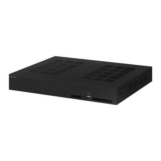
- Page 15 MBOX installation and connection MBOX -ACE Front/Rear S ide - Front IR Tx IR Rx / Power Btn USB 2.0 ※ Universial remote controller Tx ※ Remote controller Rx - Rear RS232 IR Tx DC 24V (Debug) ※ Universial remote controller Tx Optical CWDM CWDM...
-
Page 16: Precautions For Installation
MBOX installation and connection Precautions for installation ※ When stacking on the M-Box rack, install the fan on the front or rear of the rack for air circulation. MBOXACE Air vent The Wall R&D Lab... - Page 17 The screen is output based on the cabinet in the upper left. To check the screen output, connect to the Group 1 terminal of the MBOX. One MBOXACE can support only one pitch cabinet at the same time. Connect only supported cabinets when installing the product. MBOX-ACE (SBB -MBOXACE)
- Page 18 MBOX installation and connection MBOX IG and Bridge Connection (MBOXACE, External IR/ECO & BT/WIFI ) - At Bridge Box,HDBaseT Cable, Bluetooth/Wi-Fi moduleand 24pin system cable are connected - IR/ECO sensor module isconnected to IG 1 Group Bottom Sensor(Bluetooth/Wi -Fi) Bridge Box Bluetooth/Wi-Fi Cable [MBOX]...
- Page 19 MBOX installation and connection IG setting spec by screen layout - Using IG Dip Switch, Need to setVx1 / STB power/ UART output depending on screen layout(Pillar or Cable) - Setting spec by screen layout ※ Shipping condition: Pillar FWD No.1 No.2 No.3...
- Page 20 MBOX installation and connection Orderly Rolled Random Rolled ★ MBOX HDBT Connection ★ (Recommend) (Not Recommend) ⑧ For HDBT, Recommendation of cable Use HDBT cables from 15m to 100m Use Alliance recommended Cables for HDBT HDBT Alliance Site : https:/ / hdbaset.org/ hdbaset-recommended-cables/ ...
- Page 21 MBOX installation and connection MBOX HDBT connection ⑨ How to set HDBT Cable Using STP RJ45 shielded : use CAT6 or CAT7 for RJ45 Connector( RJ45 shielded andplastic Load bar) Load bar Inserting the conductor (conductor) into the plastic loader: Insert the conductor into the load bar of the RJ45 connector as shown in the conductor structure (T -568B) shown below.
- Page 22 MBOX installation and connection MBOX HDBT connection How to set HDBT Cable • Push the plastic loader in as far as possible: push the plastic load bar as close as possible to the cable • Cut all conductors leaving about 0.5” by using wire cutter •...
- Page 23 MBOX installation and connection MBOX HDBT connection ⑩ How to set HDBT Cable • The drain wire is combined on the cable jacket as shown in the figure below using pliers. • Soldering the drain wire to the metal part of the RJ45 connector: After soldering the drain wire to the metal part of the RJ45 connector, cut off the unnecessary part.
- Page 24 MBOX installation and connection Optical cable connection ① Optical cable connection Connect the optical cable from the Module Tx to the Module Rx of the cabinet. ※ When the optical modules Tx and Rx are connected, they must be connected by an optical cable without FDF connection or optical fusion.
- Page 25 MBOX installation and connection Optical cable connection ② Optical cable handling and installation * BIMMF (Bend Insensitive Multimode Fiber) For stability, use an optical cable of BIMMF , OM3 or higher, LC-LC connector type. Avoid contact devices with sharp or rough surfaces. ★...
- Page 26 ③ Cable connection As it is a common cause of malfunction, special attention is required when connecting connectors. In case of Duplex type, unlock the locking structure and connect them one by one like Simplex. MBOX-ACE Cabinet Duplex...
- Page 27 MBOX installation and connection Optical cable connection ① Connect the cable Remove the dust protection cap and connect the cable and connector in the direction as shown in the picture. Insert with low force until you hear a “click” sound. ...
- Page 28 MBOX installation and connection Optical cable connection ② Connect the cable Check that the cable is fully inserted all the way Be careful not to apply tension to the up, down, left and right sides of the optical cable The Wall R&D Lab...
- Page 29 MBOX installation and connection Optical cable connection ③ Connect the cable When disconnecting the cable, be sure to press the separation clip to separate it, and do not pull the cable alone. Do not apply force by pulling the optical cable up and down, left and right. The Wall R&D Lab...
- Page 30 MBOX installation and connection Optical cable connection ④ Optical cable Handling and installation Consider the pulling force so that the minimum force is applied to the optical fiber when installing the cable For tensile properties, refer to each cable specification ...
- Page 31 MBOX installation and connection Optical cable connection ④ Optical cable Handling and installation If you want to fix it to a tray, etc., fix it gently so that no direct pressure is applied to the optical cable . ...
- Page 32 MBOX installation and connection How to use the IR cable connection Connect the IR cable to the connector on the back of the MBOX Connect to the connector number that matches the HDMI Source output number ex) For HDMI Source #1, connect the cable to the #1 IR connector ...
- Page 33 Setting and guide The Wall R&D Lab...
- Page 34 The LED Signage Manager is an Windows application software allows you to control multiple LED Cabinets and layout remotely from a computer. • LSM Software download : Samsung Display Solutions (https://displaysolutions.samsung.com) Solutions > LED Signage Solution > LED Signage Manager...
- Page 35 First LED Cabinet and M-BOX are connected using Optical fiber and OCM cable. AOC module and IG (Interface Gender) also be inserted. Next LED Cabinets are connected sequentially using OCM cables, as per daisy-chain connection. MBOX-ACE AOC (Fiber) Interface Gender...
- Page 36 LED Signage Manager ※ samewith LSMdownload path Connect the M-BOX and your computer using LAN(RJ45) communication Select Start > All Programs > Samsung > LED Signage Manager > Network Configuration on your computer. Configure settings for Serial Port and Device ID.
- Page 37 LED Signage Manager Starting LSM, Log-in page appears to set the Password. Password should be entered twice to confirm the password. Put in desired Password twice and click Start button. Check “Don’t use password” if password is not required. LSM starts without password from next Log-in.
- Page 38 LED Signage Manager In the Connections tab, click New Connection. Connect an M-BOX using one of following options. Option 1 : Connect manually by specifying a desired M-BOX, enter the IP address, Device PINCODE and click Add. Option 2 : Click Search to add an M-BOX automatically in same network. Select the M-BOX to be connected and click Add. IP Address : IP addressof the M-BOX to be connected.
- Page 39 LED Signage Manager It is a security device PINCODE for the purpose of preventing the theft of information about M - BOX Device PINCODE is required in M -BOX model (default PINCODE : 0000) How to change PINCODE in M - Box Setting →...
- Page 40 LED Signage Manager Select Model Type ; “With Cabinet IP (4K -Pillar)” or “With Cabinet IP (8K)”. Thereafter, set IP Address for each group and number of LED cabinets connected to each group must be correctly set in * Model type the Number of Cabinets.
- Page 41 LED Signage Manager [Caution] M-BOX use 1515, 48484, 48485, 58585 ports for communication with the LED cabinets. 1. Home Window : Display the device information, Input source, LED cabinets layout and Firewall/ Security network manager has to allow those ports for M-BOX and LED Cabinets error messages, etc.
- Page 42 LED Signage Manager Connection Layout setting Adjust position and layout of LED Cabinets of the output source configuration of M-BOX. Feature View Edit buttons for connection and configuration. Auto- arrangement function also be supported. Device Information/ Setting View Shows LED Cabinet configuration and setting information. Resolution : resolution of input video source View Port: Horizontal/ Vertical size, Video Wall matrix setting, X/ Y position of origin.
- Page 43 LED Signage Manager Device connection list View: Configuration and setting of the M-BOX, Editing LED. Cabinet connection layout and Delete, LED Cabinets group information. Connection layout (View Port): Position and layout of each LED Cabinet. Category View: Home and Connections tap Device Information / Setting View: Control M-BOX setting (Screen setting) Sub Information View:...
- Page 44 LED Signage Manager 1. Basic: Power On/ Off, Video input source, Screen Mute/ Freeze, Menu size. 2. Picture: Picture Mode control, Adjust Brightness/ Contrast/ Sharpness/ Color/ Tint(G/ R)/ Color Temp(K)./ Gamma/ White Balance 3. Picture Options: Color Tone, HDMI black level, Firm Mode, etc.
- Page 45 LED Signage Manager 6. LED Cabinet Setting: Pixel RGB Data Reload/ Request, On Screen Display on/ off LED Brightness Software Upgrade (LED Cabinet) 7. LED Cabinet Calibration: Control LED Cabinet, LED module, Edge Adjust screen Gradation...
- Page 46 LED Signage Manager Monitor Window: MDC log message, connected Device information, ※ Log massage can be saved and extracted. LED Signage Cabinet: SoC and FPGA operating and Power control information of LED Cabinet LED Signage Box: IP address, MAC, ID list, number of LED Cabinets (Total/ Connected/ Unconnected), Serial Number, SW/ HW Version information...
- Page 47 LED Signage Manager Options Command retry count Error checking interval High Temperature Alarm Support Programming Log message control System Error alert mailing Password control About Software LSM software version information and upgrade...
- Page 48 S/W upgrade ■ Check software version using OSD 1. Click the "MENU" button on the remote control. 2. Please enter the “Support” menu. 3. Select “About Samsung” item. 4. You can check the SW version as follows. The Wall R&D Lab...
- Page 49 S/W upgrade ■ Check software version using Factory Mode 1. Enter the Factory mode 2. You can check the SW version as follows. Oscar - p (Main Micom) Version Oscar - p (Sub Micom) Version Oscar - p (Sub Micom) Version KU060 (FPGA #1) Version KU060 (FPGA #2) Version K325T (FPGA) Version...
- Page 50 S/W upgrade OSCAR -P Main Micom S/W Upgrade • USBupgrade • Upgrade firmware downloaded from https://displaysolutions .samsung .com website • Connectthe USBdrive where the downloaded file is stored to the mediabox. (do not disconnect power cord or USBdrive during upgrade.) •...
- Page 51 S/W upgrade Main SWUpgrade(Main-Micom) Save “T-OSCPMBAWWC” folder to the USB root. - Save the entire folder to the Root folder Connect the USB drive. Click the MENU key on the remote control. Select the “Support” menu Select the “Software Update” menu. Select the “Update Now”...
- Page 52 S/W upgrade SubMicom Upgrade Youcan upgrade SubMicom in FactoryMode. It takes about 1-2 minutes. Save “OSPMICOM_LXTV.bin ” file to the USB root. Connect the USB drive. Enter the Factory mode. Select the “SVC→UPGRADE“ menu. Move the cursor to the “SUBMICOM UPGRADE” menu. Click the Enter button.
- Page 53 S/W upgrade SE1HM02 (Novatek), KU060/K325T (FPGA) Firmware Upgrade Save the required files for each folder SE19HM02 : “SBNVT19HWWS” file to the USB root. KU060 #1 : “SBKU060AWWF1” file to the USB root. KU060 #2 : “SBKU060AWWF2” file to the USB root. K325T : “SBK325TAWWF”...
- Page 54 S/W upgrade Valens TxFirmware Upgrade • Youcan upgrade the ValensTxand Rxfirmware in FactoryMode at the sametime. It takes about 20 minutes. Save “TB -VSTXSHWWS.bin ” and "TB-VSRXSHWWS.bin " file to the USB root. Connect the USB drive Enter the Factory mode Select the “SVC→UPGRADE“...
- Page 55 Thank you End of Document The Wall R&D Lab...
Need help?
Do you have a question about the MBOX-ACE and is the answer not in the manual?
Questions and answers