
Related Manuals for Samsung SBB-CS4B


Summary of Contents for Samsung SBB-CS4B
- Page 1 23Y S -Box Installation Manual SBB -CS4B Model Name: LED Signage Box for Indoor Cabinet Series Model Code: SBB - CS4BPGS Ver 1.6 Innovative Product R&D Lab...
-
Page 2: Revision History
Revision History Version Date (Y/M/D) Description 2023/03/22 New Release 2023/04/04 Add Multi -Link HDR 2023/04/13 Add Eco sensor contents 2023/05/25 LSM specification update 2023/06/14 Add IG power case 2023/08/29 Add Device Care 2023/11/20 Add Appendix Innovative Product R&D Lab... - Page 3 Index 1. Product’s Description 2. S -Box Install preparations 3. S -BOX Installation and Connection 4. Setting and guide 5. SW Update - Appendix Innovative Product R&D Lab...
-
Page 4: Product's Description
1.Product’s Description Innovative Product R&D Lab... - Page 5 Product’s Description Model Product Appearance & Information SBB -CS4BPGS/** Remarks Innovative Product R&D Lab...
- Page 6 Product’s Description CS4B (Standard) CV4B (VP) CX4B (Outdoor) Support Model IWA-VP(P1.68), IFR/IEA, IWA-VP(P1.68), IFR/IEA, IVC XHB, XLB Maximum resolutions 4K UHD (3840 x 2160) Frame Rate Up to 60㎐ DP 1.4a HDMI 2.1 Input USB 2.0 12G-SDI Output Optic (QSFP+) 4 (SR4, LR4) 4 (SR4, LR4) 4 (LR4, SR4)
- Page 7 Product’s Description ITEM SBB-CS4B SBB-SNOWAAE SBB-SNOWJMU Support Model IWA-VP(P1.68), IFR/IEA, IWC IWA, IFA, IFR/IER/IEA IFA, IFR/IER/IEA Pontus-M Oscar-P Kant-M2e Front-end IC PS196(DP) SE19HM SE18S FPGA KU060, K200T KU060, K325T KU085 Max Screen Resolution 4k(3840x2160) 8k(7680x4320), 4k(3840x2160) 4k(3840x2160) Input HDMI(2), DP(1), USB(2)
-
Page 8: Mechanical Exploded View
Product’s Description Product Size Weight Type CX4B / CV4B / CS4B Set Size [WxDxH][mm] 440.0 x 340.0 x 60.5 (without Foot) Weight[kg] 3.95 Mechanical Exploded View Description ASSY COVER-TOP PCB MAIN PCB FPGA BRACKET-SUPPORT ASSY BRACKET P-GUIDE ASSY BRACKET-PCB Innovative Product R&D Lab... - Page 9 Product’s Description Product Size Weight Type Interface Gender Set Size [WxDxH][mm] 75.6 x 228.3 x 23.3 (without Foot) Weight[kg] Mechanical Exploded View Type Description ASSY COVER-TOP PCB SUB-IG ASSY BRACKET-PCB Innovative Product R&D Lab...
- Page 10 Install preparations 2. S -Box Innovative Product R&D Lab...
- Page 11 2. S -Box Install preparations ① Remove the tape of the top packing BOX and open the box. Check the following accessory list list while taking out the accessory components loaded in the Top–Cushion. Power cord by region POWER CODE After removing the top-cushion, take out the S-BOX inside the PE BAG and open it.
- Page 12 3. S -BOX - Installation and connection Innovative Product R&D Lab...
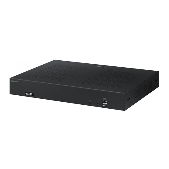
- Page 13 3. S -BOX Installation and Connection CS4B Front/Back Designation Front DVI-OUT IR Rx / Power Btn USB 2.0 (monitoring) ※ Remote control receiver *The DVI-out is used only for service purposes, so be careful not to use it when connecting the actual cabinet. Rear DC 19V RS232...
- Page 14 3. S -BOX Installation and Connection IG Front/Back Designation Front Bottom Rear Side Innovative Product R&D Lab...
- Page 15 3. S -BOX Installation and Connection S -BOX Installation Order - The SBOX installation order proceeds in four steps as follows. Source & S-BOX connection S-BOX & I/ G connection I/ G & Cabinet connection Cabinet ① S-BOX Installation Interface Gender S-BOX (CS4B) Innovative Product R&D Lab...
- Page 16 3. S -BOX Installation and Connection S -BOX Installation Order (①S -BOX Installation) - The SBB -CS4B model is designed to meet the 19 -inch standard server rack. It is recommended to install on the standard server rack when installing. ※...
- Page 17 3. S -BOX Installation and Connection S -BOX Installation Order (①S -BOX Installation) - Depending on the screen configuration, you can configure the screen using multiple S - BOXs. (Considering resolution or installation structure of 4K or more) - When configuring a screen through Multi S-BOX, connect Multi S -BOX using a network router. ※...
- Page 18 3. S -BOX Installation and Connection S -BOX Installation Order (①S -BOX Installation) - SBB -CS4B model is S - BOX that provides LED HDR function. ※ LED HDR: Dynamic Peaking technology implements excellent contrast ratio to express image quality close to real life - If a screen is configured by connecting multiple S - BOXs, the Multi - Link HDR port of S -BOX must be connected.
- Page 19 3. S -BOX Installation and Connection S -BOX Installation Order ( ②Source and S - BOX connection) - The SBB -CS4B model is an S -BOX that can receive HDMI, DP (Display Port), and SDI (Serial Digital Interface) signals. ①...
- Page 20 3. S -BOX Installation and Connection S -BOX Installation Order ( ②Source and S - BOX connection) ② Since the 1920x1080 output is the default output specification, the CS4B model must change the IG resolution setting when connecting to the 1920x2160 resolution support cabinet. (Supportability of 1920x1080 for IFR/ IEA and 1920x2160 for IWA-VP/ IWC/ IVC) <Support resolution by cabinet>...
- Page 21 3. S -BOX Installation and Connection S -BOX Installation Order ( ②Source and S - BOX connection) ※ IG Resolution value is set not to match the supported resolution If the support resolution of the cabinet connected to the IG Resolution value does not match, the screen may be broken as shown in the picture on the left.
- Page 22 3. S -BOX Installation and Connection S -BOX Installation Order ( ②Source and S - BOX connection) ※ Note (1/ 2) Please refer to the following picture for the output specification according to the IG Resolution value. When Output Resolution is UHD 1) IG Resolution : 1920x1080 Group 2 Group 3...
- Page 23 3. S -BOX Installation and Connection S -BOX Installation Order ( ②Source and S - BOX connection) ※ Note (2/ 2) Please refer to the following picture for the output specification according to the IG Resolution value. When Output Resolution is FHD 1) IG Resolution : 1920x1080 Group 2 Group 3...
- Page 24 3. S -BOX Installation and Connection S -BOX Installation Order (③S -BOXand I/G Connection) - Connect S -BOX and I/G using optical module (for SR4/LR4) and optical cable (MPO,LC type). CS4B Optical Module(SR4/LR4 용) Optical Cable (MPO,LC type) Innovative Product R&D Lab...
- Page 25 3. S -BOX Installation and Connection S -BOX Installation Order (③S -BOXand I/G Connection) ① Optical module connection - CS4B is a product that can be connected using optic transceiver (optic module) that supports 40G QSFP+ specification. - Connect the optical module to the S-BOX and I/ G connectors using the optical module (for SR4 or LR4). Short-range transmission (100m) Long-range transmission (10km) ※...
- Page 26 3. S -BOX Installation and Connection S -BOX Installation Order (③S -BOXand I/G Connection) ① Optical module connection – Precautions - The optical module specification compatible with CS4B is QSFP+40GBASE-LR4/ SR4, and it does not work when connecting optical modules of other specifications. - The following list is an optical module compatible with the CS4B model, so it is recommended to use the optical module by referring to the following list..
- Page 27 3. S -BOX Installation and Connection S -BOX Installation Order (③S -BOXand I/G Connection) ① Optical Module Connection – Notes - For LR4 / SR4 specifications, refer to the following IEEE 802.3ba specifications. Parameter Min. Typ. Max. Unit Reference Supply voltage 3.135 3.465...
- Page 28 3. S -BOX Installation and Connection S -BOX Installation Order (③S -BOXand I/G Connection) ② Optical Cable connection - When installing the optical module with LR4 specification, connect it using LC Type SMF specification optical cable. Single Mode Fiber - When installing the optical module with SR4 specification, connect using MPO Type MMF specification optical cable.
- Page 29 3. S -BOX Installation and Connection S -BOX Installation Order (③S -BOXand I/G Connection) ② Optical cable connection (connection example) When connecting LR4 When connecting SR4 When connecting LR4 When connecting SR4 <S -BOX 연결사진 > S-BOX When connecting to the LC type cable, the transmission/reception unit of the S-BOX and IG optical modules must be checked and connected.
- Page 30 3. S -BOX Installation and Connection S -BOX Installation Order (③S -BOXand I/G Connection) ② Optical cable connection - precautions - When connecting signals using optical cables, handling defects may occur, so it should be installed in consideration of the following optical cable handling specifications.
- Page 31 3. S -BOX Installation and Connection S -BOX Installation Order (③S -BOXand I/G Connection) ② Optical cable connection - precautions - When connecting signals using optical cables, handling defects may occur, so it should be installed in consideration of the following optical cable handling specifications.
- Page 32 3. S -BOX Installation and Connection S -BOX Installation Order (③S -BOXand I/G Connection) ② Optical cable connection - precautions - The CS4B model is a model that supports 40G BASE-SR4/ LR4. - When transmitting an optical signal using the SR4 optical module, it must be connected using the Multi-Mode OM3 Cable (MPO Type). (MAX installation length: 100m) - When transmitting an optical signal using the LR4 optical module, it must be connected using a single mode cable (LC type).
- Page 33 3. S -BOX Installation and Connection S -BOX Installation Order ( ④I/G and Cabinet Connection) - The CS4B model is an S -BOX compatible with IWA -VP (P1.68), IFR, IEA, IWC Cabinet. - Connect the I/G and cabinet using the OCM cable in the accessory box. - I/G is a specification that is installed in the cabinet frame together.
- Page 34 3. S -BOX Installation and Connection S -BOX Installation Order ( ④I/G and Cabinet Connection) - I / G factory shipment Dip Switch specification is 0000. (Refer to the following "shipping mode" photo) - When installing with LED cabinet, connect standby pin 4 should be turned on and installed with 0001 specificationto enter Always ON modeat all times.
- Page 35 3. S -BOX Installation and Connection S -BOX Installation Order ( ④I/G and Cabinet Connection) Screen Dip SW Video Redundancy PILLAR_DE IG Port Ethernet STB_EN Usage structure Setting Setting (Vx1) SW (UART) Cable FWD/B Installation Cable WD IG FWD/BWD same Configurati OC Cable...
- Page 36 3. S -BOX Installation and Connection S -BOX Installation Order ( ④I/G and Cabinet Connection) Screen Dip SW Video Redundancy PILLAR_DE IG Port Ethernet STB_EN Usage structure Setting Setting (Vx1) SW (UART) Cable FWD/B Installation Cable WD IG FWD/BWD same Configurati OC Cable...
- Page 37 3. S -BOX Installation and Connection S -BOX Installation Order ( ④I/G and Cabinet Connection) - IG setting can be adjusted through MDC command. Operating No.4 Specification Always On Mode set supported Shipment mode (Standby mode entry specification) Always On Mode set ■...
- Page 38 3. S -BOX Installation and Connection S -BOX Installation Order ( ④I/G and Cabinet Connection ) – Eco Sensor Installation - The CS4B model can adjust the brightness of the cabinet according to the brightness change of the external lighting using the illuminance sensor (BN96 -39535B).
- Page 39 3. S -BOX Installation and Connection S -BOX Installation Order ( ④I/G and Cabinet Connection ) – Eco Sensor Installation precautions - The illuminance sensor is a structure in which a magnet is attached to the sensor part and Bottom to the TOP. - When installing the illuminance sensor, be careful not to receive direct sunlight from external light.
- Page 40 3. S -BOX Installation and Connection S -BOX Installation Order ( ④I/G and Cabinet Connection) ※ The following connection diagram is Video Redundancy specification, Backward direction does not support data path for control operation. - IFR Screen Composition • Video: VBY1 IG #2 •...
- Page 41 3. S -BOX Installation and Connection S -BOX Installation Order ( ④I/G and Cabinet Connection ) – CX4B/CS4B - If the screen brightness is controlled using the Light/Eco Sensor, the screen brightness control operation may not be perform ed in case of communication * Dimming-Brightness Optimization Control through LSM * When a communication failure occurs with the sensor, the brightness is fixed to the default value.
- Page 42 3. S -BOX Installation and Connection Note) DVI output function for service - The DVI - OUT on the front of the product is a port used for service purposes. - The resolution of the port is FHD (1920*1080 @ 60Hz) and screen blinking and breaking may occur when entering the source of U HD resolution into S-BOX, This is a phenomenon in which the port output is fixed down scaling without a specific scaling algorithm and has nothing to d o with the actual LED...
- Page 43 Setting and guide Innovative Product R&D Lab...
-
Page 44: Setting Order
4. Setting and guide Setting order - Set 1 S -BOX setting 2 Control PC setting (LSM) in order to use S -BOX. - Connect using Lan Cable (Shield) between S -BOX ↔ Control PCs. Control PC Setting (LSM) ①... - Page 45 4. Setting and guide Precautions Before Setting - S-BOX shipment quality setting is optimized for cabinet specifications and factory shipment, and control PC ↔ S -BOX ↔ IG must be set for optimal image quality ↔Cabinet should be connected to Optical / OCM cable and installed so that it can be set through LSM. ※The color may be unnatural when the cabinet is lit after LSM is not connected between S-BOX and LED display.
- Page 46 4. Setting and guide ① S -BOX Settings – Network Settings - Enter the Home key → Device ID using the remote controller. - Change the device ID to “1” and the PC Connection Cable to “RJ -45 (LAN) Cable”. For the SBB model, the device ID is always 1.
- Page 47 4. Setting and guide ① S -BOX Settings – Network Settings - Use Remote Controller to enter Home key → Network Status.You can set up automatic IP or manual IP through IP Setting. -Set the IP according to the control PC and network environment you use. ※...
- Page 48 4. Setting and guide ① S -BOX Settings – Picture Setting - You can set Menu → Picture specifications using Remote Controller. - You can set the screen size to display as Cabinet through “LED Picture Size Settings”. <LED Picture Size Settings> Output Resolution Select UHD/FHD to match the resolution of the source entered by the Control PC.
- Page 49 4. Setting and guide ① S -BOX Settings – Picture Setting(Exceptions) - Picture Size of S -BOX does not provide overscan/ crop function by default. - If the LED Picture Size is Original or Fit to Screen is Off, the original ratio is maintained. If it is Fit to Screen On, it is adjusted to the LED Picture Size.
- Page 50 4. Setting and guide ① S -BOX Settings – Grouping setting - You can configure a single screen using multiple S -BOXs using the grouping function of S -BOX. - To use the grouping function, change the image quality settings of multiple S -BOXs to OFF except for “Picture Mode” – “Calibration” as follows. ※...
- Page 51 4. Setting and guide ① S -BOX Settings – Grouping setting - Select Home → Video Wall mode using Remote Controller. - Select Video Wall Mode as “ON”. Innovative Product R&D Lab...
- Page 52 4. Setting and guide ① S -BOX Settings – Multi -Link HDR Setting - SBB -CS4B model supports LED HDR mode. - When configuring a screen by connecting multiple S -BOX, Multi-Link HDR Setting must be turned on. (Refer to page 17) - Click the Menu button using the Remote Controller and select Screen →...
- Page 53 4. Guide for settings ① S -BOX – Device care - Check device condition of S -BOX and optimization can be performed with "Device Care“ - Menu Support Device Care ① ② ① Start Device Care : Check device condition of S -BOX automatically ②...
- Page 54 4. Setting and guide ② Video Source Settings – Change Output Frequency (PC ) - Change the output frequency of the PC as follows. • Right-click desktop mouse → Select screen resolution → Click advanced settings → Click display adapter attribute display •...
- Page 55 4. Setting and guide ② Video Source Settings – Change Output Frequency (1/3) - Support frequency of CS4B is as follows. Change the output frequency of the video source to match the corresponding support frequency. Horizontal Frequency S-BOX Grouping S Resolution Vertical Frequency (Hz) Pixel Clock (MHz) Sync Polarity (H/V)
- Page 56 4. Setting and guide ② Video Source Settings – Change Output Frequency (2/3) - Support frequency of CS4B is as follows. Change the output frequency of the video source to match the corresponding support frequency. Horizontal Frequency S-BOX Grouping S Resolution Vertical Frequency (Hz) Pixel Clock (MHz) Sync Polarity (H/V)
- Page 57 4. Setting and guide ② Video Source Settings – Change Output Frequency (3/3) - Support frequency of CS4B is as follows. Change the output frequency of the video source to match the corresponding support frequency. Horizontal Frequency S-BOX Grouping S Resolution Vertical Frequency (Hz) Pixel Clock (MHz) Sync Polarity (H/V)
- Page 58 ② Control PC Settings – LSM • LSM: Windows Application Software for remotely adjusting the layout of LED cabinets • LSM download path: Samsung Display Solutions (https://displaysolutions.samsung.com/support/resources/product -support) Search support > Enter LED Signage Manager> Click DOWNLOAD • ※ Partner login is required to download the program.
- Page 59 4. Setting and guide ② Control PC Settings – LSM When LSM is executed for the first time, a page that sets the password appears. To set the password, the user must enter the same password twice and click the Start button. If you don't want to use password, check Don't use password option.
- Page 60 4. Setting and guide ② Control PC Settings – Connect LSM To add connection information, you can enter Search or IP address directly. When you click the Search button, the IP address of the connectable S-BOX on the same network appears. If you know the IP address of S -BOX, you can also enter it directly.
- Page 61 4. Setting and guide ② Control PC Settings – Connect LSM Caution!] Fixed IP settings are recommended when setting up an LED cabinet network. If IP is changed when using DHCP, LSM connection may be disconnected. You can select With Cabinet IP (4K) according to 192.168.10.
- Page 62 4. Setting and guide [★ Caution!] ② Control PC Settings – LSM HOME Screen For internal communication between S -BOX and LED Cabinet, use ports 1515, 48484, 48485, and 58585. During firewall/security network use, the port must be enabled between S-BOX and LED.
- Page 63 4. Setting and guide ② Control PC Settings – Edit Connection Connection layout: Adjust the location and layout of each LED cabinet in the output source area of the S -BOX. Feature View: Provides an Edit button to modify connection information and automatic alignment of LED cabinets.
- Page 64 4. Setting and guide ② Control PC Settings – Diagnostic Status Change View Mode to “Diagnostic Status” to check the diagnostic function of LSM. Innovative Product R&D Lab...
- Page 65 4. Setting and guide ② Control PC Settings – Diagnostic Status (S - BOX) Signal In: Check if the input video signal is received normally. Temperature (°C): Shows the current temperature of S - BOX. FAN: Check if Fan is operating normally. Displays “Normal” when normal and “Error”...
- Page 66 4. Setting and guide ② Control PC Settings – Diagnostic Status (Cabinet) T-CON: Shows whether the T - CON of the cabinet works normally. SMPS: Shows whether the SMPS of cabinet is ON/OFF. Module: Shows whether the module works normally. Temperature: The current temperature of the cabinet is shown in a picture.
- Page 67 4. Setting and guide ② Control PC Settings – 1. Basic : . On / Off, change input source, Screen Mute / Freeze 2. Picture . Picture Mode change, Brightness / Contrast / Sharpness, Color, Tint(G/R), Color Temp(K), Gamma, White Balance adjustment, etc. 3.
- Page 68 4. Setting and guide ② Control PC Settings – 6. Cabinet Settings . Pixel RGB Data Reload / Request . OnScreenDisplay On / Off . Adjust LED Brightness . VP HDR Mode On / Off . Software Update function 7.
- Page 69 4. Setting and guide ② Control PC Settings – 8. Light Sensor Setting - On Brightness Optimization for Illuminance Sensor On or On Adaptive Picture * Both can't be turned on. Innovative Product R&D Lab...
- Page 70 4. Setting and guide ② Control PC Settings – Monitor Window: MDC communication log and connection device information can be checked Extractable as a file LED Signage Cabinet: IC information and power information of LED cabinet F/W information of IG LED Signage Box: IP address, MAC address, ID range of LED cabinet, Number of LED cabinets (full / connected /...
- Page 71 4. Setting and guide ② Control PC Settings – Options Command retry count Error status check interval Temperature warning notification S-Box Clock sync Support Program language Log data management Notification of device error through mail Password Configuration Options About Software Current version and update function of Innovative Product R&D Lab...
- Page 72 5. SW Update Innovative Product R&D Lab...
- Page 73 5. SW Update Software Update - Check software update version ※ Contact Samsung Entry: MENU -> Support -> Contact Samsung Pontus-m (Main Micom) Version Pontus-m (Sub Micom) Version KU060 (FPGA) Version 7A200T (FPGA) Version Innovative Product R&D Lab...
- Page 74 ① Pontus -M Main Micom Software Upgrade • USBDownload " https://displaysolutions.samsung .com/support/resources/product-support " Upgradefirmware downloaded from the website 1. Connectthe USBdrive where the file is stored to the set. (Pleasebe careful not to disconnect the power or USBdrive during the upgrade.) 2.
- Page 75 5. SW Update Software Update – Update using USB ① Main SWUpgrade Save the “SB -PTMWWC” folder to the USB root. Connect the USB. Click the “MENU” key on the remote control. Select the “Customer Support” menu. Select the “Update Software” menu. Select the “Update Now”...
- Page 76 5. SW Update Software Update – Update Using LSM (S -BOX) 1. Prepare the update SW File. (Files selected when updating files marked in red) 2. After connecting LSM and CS4BPGS , click the Software update button under the S-Box Settings > System menu . 3.
- Page 77 5. SW Update Software Update – Update Using LSM (S -BOX) 1. Prepare the update SW File. (Files selected when updating files marked in red) 2. After connecting LSM and CS4BPGS , click the Software update button under the S-Box Settings > System menu . 3.
- Page 78 5. SW Update Software Update - Update Using LSM ( IG) 1. Prepare the update SW File. (Files selected when updating files marked in red) 2. After connecting LSM and CS4BPGS , click the Software update button under the Cabinet Settings > System menu . 3.
- Page 79 5. SW Update Software Update - Update Using LSM ( IG) 1. Prepare the update SW File. (Files selected when updating files marked in red) 2. After connecting LSM and CS4BPGS , click the Software update button under the Cabinet Settings > System menu . 3.
- Page 80 Appendix IG POWER CASE [CASE 1] Always ON mode (IG 4 deep switch ON) ※ Recommended installation specifications Cabinet Cabinet S-BOX/IG S-BOX Group screen Group screen POWER OFF POWER ON Always ON mode - In case of CASE 1, IG enters Always on state regardless of S-BOX signal. [CASE 2] Standby mode (IG 4 deep switch OFF) Cabinet Cabinet...
- Page 81 Appendix IG POWER CASE – [CASE 1] - In the case of CASE 1, since the power of the IG is always on, there is no need to connect the IR for the front to turn on ea ch IG (Forward). - You can use IR for one front to control the OSD menu.
- Page 82 Appendix IG POWER CASE – [CASE 2] - In case of CASE 2, AC power of Cabinet must be turned off -> ON to turn on power of IG. - If the above method is difficult, you can apply power by connecting IR for Front to the installed S - BOX and each IG (Forward). ( Note: See p41) BN39-01899A (※...
- Page 83 Appendix IG POWER CASE – [CASE 2] ※ For front IR installation, the screen is not turned on, the cabinet group where IR is not installed, so be careful. Innovative Product R&D Lab...
- Page 84 Thank you End of Document Innovative Product R&D Lab...
Need help?
Do you have a question about the SBB-CS4B and is the answer not in the manual?
Questions and answers