Table of Contents
Advertisement
Quick Links
Advertisement
Table of Contents

Related Manuals for Yaesu FTM-150R


Summary of Contents for Yaesu FTM-150R
- Page 1 VHF/UHF DUAL BAND FM TRANSCEIVER FTM-150R FTM-150E Operating Manual...
-
Page 2: Table Of Contents
Installing the Radio ........30 Text input screen .......... 65 About the antenna ........30 Specifications ..........66 YAESU LIMITED WARRANTY ...... 68 Connection of Antenna and Power Cables .. 30 Installing the Transceiver/Microphone ..31 Install the main body using the supplied bracket .......... -
Page 3: Introduction
Heavy Duty-Heat Sink with FACC (Funnel Air-Convection Conductor) m Compatible with microSD memory cards Thank you for purchasing the FTM-150R/E Transceiver. We urge you to read this manual in its entirety, and also the Advance Manual (available for download on the Yaesu website), to gain a full understanding of the amazing capability of the exciting new FTM-150R/E Transceiver. -
Page 4: Quick Guide
Quick Guide VOL/SQL Knob VOL/SQL Knob Power Switch DIAL Knob DIAL Knob Turn the Power ON Transmit/Receive Signals Talk into the microphone while holding the Press and hold the key. PTT switch on the side. Release the PTT Switch the operating band switch to return to receive. -
Page 5: Supplied Accessories And Options
Supplied Accessories and Options Supplied Accessories • DTMF microphone SSM-85D • DC power cable (with fuse attached) • Bracket for main body • Spare fuse (15A) • Operating Manual (This Manual) If any item is missing, contact the dealer from which you purchased the transceiver. Available Options • Swing Head Kit SJMK-500... -
Page 6: Basic Operation
Basic Operation Turning the Transceiver ON switch to turn the transceiver ON / OFF. 1. Press and hold the Press and hold Adjusting the volume 1. Rotate the VOL knob to adjust the volume to a comfortable level. Adjust the volume level Adjust the volume level for Left Side Band for Right Side Band... -
Page 7: Selecting A Frequency Band
Selecting a Frequency Band Press the key to select the desired frequency band. Press AIR Band 108MHz - 137MHz 144MHz/VHF Band 137MHz - 174MHz VHF/UHF Band 174MHz - 400MHz 430MHz/UHF Band 400MHz - 550MHz • With the “band skip function”, specific bands may be selected to be used. Even when the band skip is set so that some frequencies cannot be selected, frequently used frequencies can be recalled by saving them into the memory channels before setting band skip. -
Page 8: Tuning To A Frequency
Tuning to a Frequency 1. Press the key to select the desired frequency band. 2. Rotate the DIAL knob to select the de- sired frequency. AIR Band 108MHz - 137MHz 144MHz/VHF Band 137MHz - 174MHz VHF/UHF Band 174MHz - 400MHz 430MHz/UHF Band 400MHz - 550MHz z Keyboard frequency entry (Direct Input) 1. -
Page 9: Switch Between Main Band And Sub Band
z The numeric keys on microphone Press the numeric keys “0” to “9” to enter the frequency. Example: To input 145.525MHz [1] [4] [5] [5] [2] Example: To input 430.000MHz [4] [3] [Press and hold any numeric key] While entering a frequency using the numeric keys, the entry may be canceled by pressing PTT. -
Page 10: Useful Functions
Useful Functions CFL: Custom Function List ..........page 16 From 62 items of the Setup Menu, frequently used functions in the Function List can be registered and then recalled by simply pressing the key. The Function List screen displays the registered functions and current settings in an easy-to-read form, so you can immediately select and use the function. -
Page 11: Pmg (Primary Memory Group)
PMG (Primary Memory Group) ..........page 14 The PMG function allows registration of up to five often used frequencies for easy monitoring. Simply press and hold the key to register the currently displayed VFO or Memory Channel frequency. The PMG screen can be switched to auto mode or manual mode by pressing and holding the Right DIAL knob. -
Page 12: Band Scope
Band Scope ................page 12 The receive status (signal strength) of the channels above and below the current frequency can be displayed as a bar graph, whether in VFO mode or in memory mode. Press and hold the key to display the Press and hold: Displays the band scope band scope screen. -
Page 13: Setup Menu List
Setup Menu List Frequently used items from the below 62 Setup Menu types, can be registered to the Function List. (See page 16) The gray Setting items are registered in the Func- tion List by factory default. See page 60 for detail information on the Setup Menu. DISPLAY SIGNALING 1 KEYPAD... -
Page 14: Switch Between Dual Receive And Scope Operation With One Touch
Switch between Dual receive and Scope operation with one touch Dual receive and Scope operations are switched each time the key is pressed and held. The center frequency or memory channel can be changed by turning the Left DIAL knob: In VFO Mode, press and hold the Right DIAL knob, then turn the Right DIAL knob to select the frequency in 1MHz increments. -
Page 15: Select The Signal Bar On The Scope To Hear The Audio
Select the signal bar on the scope to hear the audio Receiving this signal • The left DIAL knob moves the bar without moving the marker. • Receive the desired signal to hear by aligning the bar with the center marker. Marker Rotate the Left DIAL knob Align the bar of the signal you want to... -
Page 16: Pmg (Primary Memory Group)
PMG (Primary Memory Group) The PMG function scans up to 5 channels registered to the PMG. The receive status of each channel is simultaneously displayed in real time with a bar graph. In addition, two channels with signals are simultaneously received, allowing convenient standby. In manual mode, transmit and receive are fixed to the selected channel, and signals are received simultaneously on other channels. - Page 17 On the PMG screen, rotate the Right DIAL knob to select the channel to be heard. The channel number display will be inverted to indicate the received channel. Press and hold the Right DIAL knob Switch between Manual Mode and Auto Mode. Press and hold MANUAL Mode While continuously receiving on the PMG channel selected with the DIAL knob.
-
Page 18: Change Feature Settings
Change feature settings Setting functions using the function list 1. Press the key. The Function List is displayed. 2. Rotate the Right DIAL knob to select the desired function. 3. Press the Right DIAL knob to execute functions or change settings. Close the function List Press any key or DIAL knob, other than the key, to save the settings and... -
Page 19: Swapping Functions In The Function List
Swapping functions in the function list Easily operate frequently used functions by calling them from the function list with one- touch operation of the key. The list of registered priority functions and the setting status can be viewed at a glance. Change the function or change the setting just by se- lecting and pressing with the DIAL knob. -
Page 20: Super Dx Plus Noise Cancelling
Super DX plus Noise Cancelling The Super DX function increases the sensitivity of the RF amplifier when the received signal is weak, expanding the calling range. In addition, by installing the Audio Digital Signal Processing Unit “SPU-1”, the received audio signal can be digitally processed to separate and remove noise. -
Page 21: Name And Function Of Each Component
Name and function of each component Control Head (front) VOL/SQL knob Mode indicator Rotate the VOL/SQL Knob to adjust the audio vol- The current operating mode is indicated by the ume level. color of the LED. VOL/SQL knob (Left): Left Side Band Green: During receive VOL/SQL knob (Right): Right Side Band... -
Page 22: Control Head (Top)
Control Head (top) Enables the Super DX function and increases sen- • Press: sitivity. Installation of the “SPU-1”, provides even Displays PMG (Primary Memory Group). (see greater noise reduction and clearer audio. page 14) Press and hold the Right DIAL knob to switch between auto mode and manual mode. -
Page 23: Control Head (Left And Right Side)
Press and hold this key to switch the power ON or • Press: OFF. Display the CFL (Customized Function List) When the power is ON, press this key briefly to screen. Rotate the Right DIAL knob to select an engage, or release the key lock. item and perform the functions and make set- tings. -
Page 24: Main Body (Front)
DATA Jack Use a Clone cable (CT-166) to connect to another FTM-150R/E. All data stored in one FTM-150R/E can be transferred to another FTM-150R/E by uti- lizing the handy “Cloning” feature. Refer to the Advanced Manual which may be downloaded from the Yaesu website. -
Page 25: Microphone (Ssm-85D)
Microphone (SSM-85D) DTMF keypad Speak into the microphone during transmission. Press these keys during transmit to enter and send a DTMF sequence. The following operations can TX LED be performed during receive. Lights red while pressing PTT switch. DTMF cannot be sent while transmitting u s i n g t h e 2 n d P T T ( s e e n e x t p a g e ) Press and hold the PTT switch to transmit, and re- assigned to a program key (P1/P2/P3/P4). - Page 26 Program keys (P1/P2/P3/P4) The default function settings of the [P1] / [P2] / [P3] / [P4] keys are shown in the table below. Default Settings Function 2nd PTT Transmit on the SUB Band frequency (The band displayed with small numbers) HOME CH Recalls the HOME channel TX POWER...
-
Page 27: Display
Display Lights when the mute function is activated Repeater Shift Direction Lights when AUTO DIALER function is enabled Lights when Auto Power Off is activated Lights when Bluetooth function is activated Lights when VOX function is activated LOCK Display of settings such as DCS/TONE Lights when a microSD memory card is inserted Displays mode... - Page 28 Repeater minus (-) shift Repeater plus (+) shift Split operation Skip Memory Channel (Permits designating undesired channels to be skipped during scanning.) Bell function is activated. Tone Encoder (tone frequency is displayed) Tone Squelch (tone frequency is displayed) Reverse Tone (tone frequency is displayed) DCS (Digital Code Squelch) (DCS code is displayed) No-communication Squelch Pager (EPCS)
-
Page 29: Descriptions Of Main Screens
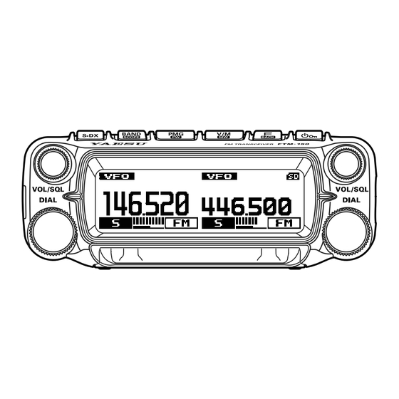
Descriptions of Main Screens z Normal screen (VFO screen) Main-band and Sub-band are displayed in a Left-Right fashion. Both bands are received simultaneously. z Mono Band screen (VFO screen) Mono-band operation Only one band is displayed large. *Simultaneous reception is not possible when using mono band. -
Page 30: Safety Precautions ( Be Sure To Read )
Be sure to read these important precautions, and use this product safely. Yaesu is not liable for any failures or problems caused by the use or misuse of this product by the purchas- er or any third party. Also, Yaesu is not liable for damages caused through the use of this product by the purchaser or any third party, except in cases where ordered to pay damages under the laws. - Page 31 Never cut off the fuse holder of the DC power cord. When transmitting, keep the antenna at least 1.8m This may cause short-circuiting and result in ignition (VHF) or 2.2m (UHF) away from your body.Do not and fire. use modified or damaged an-tennas. Do not use fuses other than those specified.
-
Page 32: Installing The Radio
Installing the Radio About the antenna The antenna is an extremely important part for both transmitting and receiving. The antenna type and its inherent characteristics determine whether the performance of the transceiver can be fully realized. As such, please note the following: ... -
Page 33: Installing The Transceiver/Microphone
Installing the Transceiver/Microphone The control head and main body are connected with a control cable. When needed, use the optional Control Cable 20ft (6m) to connect the main body to the “CONTROL” terminal of the control head. Connect the supplied microphone SSM-85D to the “MIC” terminal of the transceiver or control head. -
Page 34: Using A Micro Sd Memory Card
• A microSD memory card that was used in another device may not function properly, for example, it may not be recognized by the FTM-150R/E, or reading and writing may take an unusually long time. Use of the SD Memory Card Formatter provided by the SD Association may improve this. -
Page 35: Functions To Use As Needed
Functions to use as needed Changing the Transmit Power Level With the factory settings, the transmit power level changes from “HIGH” to “LOW” to “MID” when the microphone [P3] key is pressed (see the table below). The transmit power lev- el can also be changed using the function List. -
Page 36: Changing The Frequency Step
Changing the Frequency Step The DIAL knob rotation frequency step may be changed. Normally, use the factory default setting of “AUTO”. 1. Press and hold the key. 2. Rotate the Right DIAL knob to select [26 STEP], then press the Right DIAL knob. 3. -
Page 37: Repeater Operation
If you need to access the repeaters which requires a 1750Hz burst tone for access by the FTM-150R (USA versions), you can set the program key on the microphone to serve as a “T-CALL” key instead. To change the configuration of this switch, use setup menu... -
Page 38: Using The Memory
Using the Memory The FTM-150R/E incorporates a Large number of memory channels that can register the operating frequency, communication mode, and other operational information. • 999 Memory Channels • 4 Home Channels • 50 pairs PMS Memory Channels m The memory auto grouping (MAG) function can automatically recall a list of memory channels from the same frequency band as a group. -
Page 39: Recall Memory (There Are Three Ways)
3. Press and hold the key. If the memory channel already contains frequency data, “OVER WRITE?” will appear on the screen. Press and hold the key to overwrite the mem- ory channel. 4. Press the key, and the screen returns to the previous display. Recall memory (There are three ways) (1) Press the 1. - Page 40 (3) Recalling a memory by directly entering the channel number z Recalling a memory on the keypad screen 1. Press the key. 2. Rotate the Right DIAL knob, select [KEYPAD], then press the Right DIAL knob to display the direct fre- quency input screen.
-
Page 41: Copy Memory Channel Information To Vfo
Copy memory channel information to VFO 1. Press the key while recalling memory. 2. Rotate the Right DIAL knob to select [M->V], then press the Right DIAL knob. Copy the contents of the recalled memory channel to the VFO and enter VFO mode. Displaying a list of memory channels in memory mode Turning the DIAL knob in memory mode usually increases or decreases the mem- ory channel number. -
Page 42: Recall Only Memories In The Same Frequency Band (Band) Using The Memory Auto Grouping (Mag) Function
Recall only memories in the same frequency band (Band) using the memory auto grouping (MAG) function With the memory auto grouping (MAG) function, only memory channels in the same frequency band (Band) can be called. In the memory mode, each time the key is pressed, Press only memory channels of the specified frequency band are... -
Page 43: Registering Frequently Used Memory Channels In M-Grp (Memory Group)
Registering frequently used memory channels in M-GRP (Memory Group) 1. Press and hold the key in VFO or memory mode. The memory channel list is displayed. 2. Rotate the Right DIAL knob to select the memory channel to be registered in the M-GRP. 3. -
Page 44: Edit Memory
Edit memory z Edit memory tag Memory name tags, such as a call sign or broadcast station name may be assigned to the memory channels and home channels. Input a memory tag using up to 8 characters. Alphabetic characters (upper and lowercase), Numbers and Symbols may be entered to the memory name tag. - Page 45 When the memory is called up, pressing the DIAL knob briefly will switch the display. TAG display Frequency display z Clearing Memories 1. Press and hold the key. The memory channel list appears. The lowest avail- able number is selected. The memory channel list can also be displayed by the following operations: Press the...
-
Page 46: Recalling The Home Channels
Recalling the Home Channels z Recall with the programmable key on the microphone 1. Press the [P2]* key on the microphone. * This is the factory setting. This function can also be assigned to the [P1], [P3] or [P4] key (see page 24). -
Page 47: Split Memory
Split Memory Two different frequencies, one for receive and another for transmit, can be registered to a memory channel. 1. Register the receive frequency to a memory channel first. For additional details on registering to a memory channel, refer to page 36. To edit a memory channel that has already been written, go to step 2. -
Page 48: Scanning Function
Scanning Function The FTM-150R/E supports the following three scanning functions: • VFO Scan • Memory Scan • Programmable Memory Scan (PMS) VFO Scan / Memory Scan To find frequencies where there are signals in VFO mode or Memory mode: 1. Press the key to select the “VFO mode”... -
Page 49: Skip Memory Channels
PMS Programmable Memory channels. 50 sets of PMS memory channels (L01/U01 to L50/U50) are available. For additional details on the Programmable Memory Scan (PMS) and Memory Bank Scan, refer to the Advanced Manual which may be downloaded from the Yaesu website. -
Page 50: Convenience Features
Convenience Features ® Bluetooth Operation (Requires optional BU-5) The FTM-150R/E can be equipped with the Bluetooth function by installing the option- ® al Bluetooth unit “BU-5”. Remote operation is possible using the optional Bluetooth ® ® headset (SSM-BT20) or a commercially available Bluetooth headset. - Page 51 While connected to a Bluetooth headset, the ® “ ” icon lights up on the FTM-150R/E screen, and the received audio and operation beep will be heard from the Bluetooth headset. ® • The LED of SSM-BT20 blinks blue. The pairing is completed.
- Page 52 (when the VOX function is OFF) When the VOX function is OFF, pressing the “Call button”* on the Bluetooth headset ® once will engage the FTM-150R/E in transmit, and then a call can be made using the Bluetooth headset. ®...
- Page 53 Connect with another Bluetooth headset ® 1. Turn the Bluetooth headset you are currently using ® OFF. 2. Press and hold the key. 3. Rotate the Right DIAL knob to select [50 Bluetooth], then press the Right DIAL knob. 4. Rotate the Right DIAL knob to select [DEVICE], then press the Right DIAL knob.
- Page 54 ® Bluetooth received audio output ® When a Bluetooth headset is connected, the received audio can automatically be output from the headset only, or from both the headset and the transceiver speaker. 1. Press and hold the key. 2. Rotate the Right DIAL knob to select [50 Bluetooth], then press the Right DIAL knob.
-
Page 55: Vox Operation
VOX Operation Using a Bluetooth headset, you can transmit hands-free automatically, just by speak- ® ing into the microphone. Setting VOX function 1. Press and hold the key. 2. Rotate the Right DIAL knob to select [9 VOX], then press the Right DIAL knob. 3. -
Page 56: Dual Receive Function
Dual Receive Function While receiving on the VFO or Memory Chanel, the transceiver checks for signals on the HOME channel once every 5 seconds. When a signal is received on the HOME channel, the priority scan pauses, allowing reception of the signal. When there is no signal on the HOME channel for about 5 seconds, the transceiver will resume Priority Scan. -
Page 57: Using The Voice Recorder
Using the Voice Recorder The receive audio can be recorded and then played back later using the optional voice guide unit “FVS-2”. The frequency of the operating band can also be announced by voice when the announce function is set to ON. Installing the Voice Guide Unit “FVS-2”... - Page 58 Setting the voice memory operation 1. Press and hold the key. 2. Rotate the Right DIAL knob to select [51 VOICE MEMORY], then press the Right DIAL knob. 3. Rotate the Right DIAL knob to select [PLAY/REC], then press the Right DIAL knob. 4.
-
Page 59: Stop Playback
Playback the recorded audio 1. Press and hold the key. 2. Rotate the Right DIAL knob to select [53 TRACK SELECT], then press the Right DIAL knob. 3. Rotate the Right DIAL knob to select the track num- ber to be replayed. When “ALL”... -
Page 60: Voice Announcement Of The Operating Frequency
Voice announcement of the operating frequency Setting the announce function operation Set the following voice announcement parameters: • Automatically announce the frequency or not • Announce the frequency in English or Japanese • Voice announcement audio level • Mute the receive audio during a voice announcement. 1. Press and hold the key. 2. Rotate the Right DIAL knob to select [51 VOICE MEMORY], then press the Right DIAL knob. 3. -
Page 61: Weather Broadcast Reception
Weather Broadcast Reception The FTM-150R/E includes a unique feature which allows reception of weather broad- casts in the 160MHz frequency range. Ten standard Weather Broadcast channels are preloaded into a special memory bank. To listen to a Weather Broadcast Channel (Example: When “WX” is assigned to [P4]): 1. -
Page 62: Using Setup Menu
Using Setup Menu The Set Mode permits configuring the various functions to accommodate individual op- erating needs and preferences. Setup Menu Operation 1. Press and hold the key. The SETUP MENU screen will be displayed. 2. Rotate the Right DIAL knob to select the desired item in the Setup Menu, then press the Right DIAL knob. -
Page 63: Tables Of Setup Menu Operations
Tables of Setup Menu Operations Selectable options Menu Number / Item Description (Options in bold are the default settings) DISPLAY Enter frequency directly or display 1 KEYPAD memory channel list. Sets the display and key button 2 LCD DIMMER MAX / MID / OFF brightness. - Page 64 Selectable options Menu Number / Item Description (Options in bold are the default settings) OFF / 2nd PTT / SCAN / HOME CH / RPT SHIFT / REVERSE / TX POWER / SQL OFF / T-CALL / VOICE* / WX / DW Microphone P1 / P2 / P3 / P4 keys (*requires optional FVS-2) 25 MIC PROGRAM KEY...
- Page 65 The frequency of the operating band 57 VOICE GUIDE – will be announced. CLONE/RESET 58 This Other Send all settings to other FTM-150R/E – Receive all settings from other FTM- 59 Other This – 150R/E 60 SOFTWARE VERSION Display the software version.
-
Page 66: Restoring To Defaults (Reset)
Restoring to Defaults (Reset) Caution When the All Reset function is performed, all data registered in the memory will be deleted. Be sure to note the settings on paper or back up the data on a microSD memory card. All Reset To restore all transceiver settings and memory content to the factory defaults. -
Page 67: Text Input Screen
Text input screen The keyboard screen is displayed when entering memory channel tag. z Character input method 1. Rotate the Right DIAL knob to select a character, then press the Right DIAL knob. 2. The selected character is entered and the cursor moves right in the text input area. -
Page 68: Specifications
Specifications z General Frequency Range : TX 144 - 148MHz or 144 - 146MHz 430 - 450MHz or 430 - 440MHz (Depends on the transceiver version) : RX 108 - 137MHz (AIR Band) 137 - 174MHz (144MHz HAM / VHF Band) 174 - 400MHz (VHF Band / UHF Band) 400 - 550MHz (430MHz HAM / UHF Band) Channel Steps... -
Page 69: About Internal Spurious Signals
z Receiver Circuit Type : Double-Conversion Super heterodyne Intermediate Frequency : 1st: MAIN Band 56.75MHz 1st: SUB Band 55.85MHz 2nd: MAIN Band, SUB Band 450kHz Sensitivity : 0.8μV typ for 10dB SN (108 - 137MHz, @AM) 0.2μV for 12dB SINAD (137 - 140MHz, @FM) 0.2μV for 12dB SINAD (140 - 150MHz, @FM) 0.25μV for 12dB SINAD (150 - 174MHz,@FM) 0.3μV typ for 12dB SINAD (174 - 222MHz, @FM) 0.25μV typ for 12dB SINAD (222 - 300MHz, @FM) 0.8μV typ for 10dB SN (300 - 336MHz, @AM) 0.25μV typ for 12dB SINAD (336 - 420MHz, @FM) 0.2μV for 12dB SINAD (420 - 470MHz, @FM) 0.2μV typ for 12dB SINAD (470 - 550MHz, @FM) Selectivity (-6 dB/-60 dB) : NFM, AM 12 kHz / 30 kHz AF Output : 3W (8 Ω, THD10%, 13.8 V) Front Speaker... -
Page 70: Yaesu Limited Warranty
Limited Warranty is valid only in the country/region where this product was originally purchased. On-line Warranty Registration: Thank you for buying YAESU products! We are confident your new radio will serve your needs for many years! Please register your product at www.yaesu.com - Owner’s Corner... - Page 71 YAESU dealer/distributor from whom the product was originally purchased. 2. Include proof of original purchase from an authorized YAESU dealer/distributor, and ship the product, freight prepaid, to the address provided by the YAESU Service Center in your country/ region.
- Page 72 Changes or modifications to this device that are not expressly approved by YAESU MUSEN could void the user’s authorization to operate this device. This device complies with part 15 of the FCC Rules. Operation is subject to the following two conditions: ( 1 ) This device may not cause harmful interference, and ( 2 ) this device must accept any interference including received, interference that may cause undesired operation.
-
Page 73: Eu Declaration Of Conformity
Telephone: (714) 827-7600 EU Declaration of Conformity We, Yaesu Musen Co. Ltd of Tokyo, Japan, hereby declare that this radio equipment FTM-150E is in full compliance with EU Radio Equipment Directive 2014/53/EU. The full text of the Declaration of Conformity for this product is available to view at http://www.yaesu.com/ jp/red ATTENTION –... - Page 74 Copyright 2024 YAESU MUSEN CO., LTD. All rights reserved. No portion of this manual may be reproduced without the permission of YAESU MUSEN CO., LTD. YAESU MUSEN CO., LTD. Omori Bellport Building D-3F 6-26-3 Minami-Oi, Shinagawa-ku, Tokyo, 140-0013, Japan YAESU USA...
Need help?
Do you have a question about the FTM-150R and is the answer not in the manual?
Questions and answers