
Subscribe to Our Youtube Channel
Related Manuals for Air-Con A17EM4C4M09


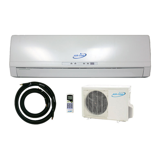
Summary of Contents for Air-Con A17EM4C4M09
-
Page 1: Service Manual
SERVICE MANUAL AIR-CON SILVER SERIES DC INVERTER SPLIT WALL-MOUNTED AC A17EM4C4M09 / A17CI4C4M09 A18EM4C4M12 / A18CI4C4M12 A17EM4C4M18 / A17CI4C4M18 A22EM4C4M24 / A22CI4C4M24 V1.0 Oct, 2009... -
Page 2: Table Of Contents
CONTENTS 1. Precaution ..............................1 1.1 Safety Precaution ..............................1 1.2 Warning ................................1 2. Function................................ 4 3. Dimension ..............................6 3.1 Indoor Unit ................................6 3.2 Outdoor Unit ................................ 7 4. Specification ..............................8 5. Refrigerant cycle diagram .......................... 8 6. -
Page 3: Precaution
1. Precaution installation stand. 1.1 Safety Precaution It may cause injury, accident, or damage to the To prevent injury to the user or other people product. Be sure the installation area does not and property damage, the following instructions must be followed. - Page 4 It may cause corrosion on the product. Corrosion, arrives. particularly on the condenser and evaporator fins, There is risk of property damage, failure of product, could cause product malfunction or inefficient or electric shock. operation. Do not open the inlet grill of the product during operation.
- Page 5 The chemical in batteries could cause burns or your skin or clothes, wash it well with clean other health hazards water. Do not use the remote of the batteries have leaked.
-
Page 6: Function
2. Function Indoor unit Operation by remote controller Sensing by room temperature Room temperature sensor. Pipe temperature sensor. Room temperature control Maintain the room temperature in accordance with the setting temperature. Anti-freezing control in cooling Prevent the water being frozen on evaporator by sensing the evaporator pipe temperature in cooling mode Ionizer (Optional) Time Delay Safety control... - Page 7 Outdoor unit Power relay control The unit has 3 mins delay between continuously ON/OFF operations. Low ambient kit The unit can operate in cooling mode at low ambient temperature conditions. Low noise air flow system Bird tail propeller fan makes the outdoor unit run more quietly. Hydrophilic aluminum fin The hydrophilic fin can improve the heating efficiency at operation mode.
-
Page 8: Dimension
3. Dimension 3.1 Indoor Unit Dimension Mode MSC-09CRDN1-NR0 MSC-12CRDN1-NR0 MSC-18CRDN1-NQ0 MSC-24CRDN1-NQ0W 1080... -
Page 9: Outdoor Unit
3.2 Outdoor Unit Dimension Mode... -
Page 10: Specification
4. Specification Please see the special file about the specifications. 5. Refrigerant cycle diagram Cooling only... -
Page 11: Wiring Diagram
6. Wiring diagram 6.1 Indoor Unit MSC-09CRDN1-NR0 MSC-12CRDN1-NR0 MSC-18CRDN1-NQ0... -
Page 12: Outdoor Unit
MSC-24CRDN1-NQ0W 6.2 Outdoor Unit MOA-09CDN1-NR0... - Page 13 MOB-12CDN1-NR0...
- Page 14 MOC-18CDN1-NQ0...
-
Page 15: Installation Details
MOF-24CDN1-NQ0W 7. Installation details 7.1 Wrench torque sheet for installation Outside diameter Torque inch Kgf.m Ф6.35 Ф9.53 Ф12.7 Ф15.9 7.2 Connecting the cables The power cord of connect should be selected according to the following specifications sheet. Grade Unit... -
Page 16: Pipe Length And The Elevation
7.3 Pipe length and the elevation Standard Max. Max. Additional Pipe size Capacity length Elevation Length refrigerant Btu/h Liquid B (m) A (m) (g/m) 3/8’’ (Ф9.53) 1/4’’ (Ф6.35) 1/2’’ (Ф12.7) 1/4’’ (Ф6.35) 1/2’’ (Ф12.7) 1/4’’ (Ф6.35) 5/8’’ (φ15.9) 3/8’’ (φ9.53) Caution: Capacity is base on standard length and maximum allowance length is base of reliability. - Page 17 If gas leakage is discovered in step (3) above, take Procedure 1. Recheck the piping connections. the following measures. 2. Open the valve stem of the 2-way valve If the leaks stop when the piping connections are counterclockwise approximately 90’, wait 10 tightened further, continue working from step (4).
-
Page 18: Pumping Down (Re-Installation)
7.5 Pumping down (Re-installation) Procedure 1. Confirm that both the 2-way and 3-way valves are set to the opened position. Remove the valve stem caps and confirm that the valve stems are in the opened position. Be sure to use a hexagonal wrench to operate the valve stems. 2. -
Page 19: Re-Air Purging (Re-Installation)
7.6 Re-air purging (Re-installation) Procedure: 1. Confirm that both the 2-way and 3-way valves are set to the closed position. 2. Connect the charge set and a charging cylinder to the service port of the 3-way valve. Leave the valve on the charging cylinder closed. 3. -
Page 20: Balance Refrigerant Of The 2-Way, 3-Way Valves
7.7 Balance refrigerant of the 2-way, 3-way valves Procedure: 1. Confirm that both the 2-way and 3-way valves are set to the open position. 2. Connect the charge set to the 3-way valve’s service port. Leave the valve on the charge set closed. Connect the charge hose with the push pin to the service port. -
Page 21: Evacuation
7.8 Evacuation Procedure: 1. Connect the vacuum pump to the charge set’s centre hose. 2. Evacuation for approximately one hour. Confirm that the gauge needle has moved toward -0.1 Mpa (-76 cmHg) [vacuum of 4 mmHg or less]. 3. Close the valve (Low side) on the charge set, turn off the vacuum pump, and confirm that the gauge needle does not move (approximately 5 minutes after turning off the vacuum pump). -
Page 22: Gas Charging
7.9 Gas charging Procedure: 1. Connect the charge hose to the charging cylinder. Connect the charge hose which you disconnected from the vacuum pump to the valve at the bottom of the cylinder. 2. Purge the air from the charge hose. Open the valve at the bottom of the cylinder and press the check valve on the charge set to purge the air (be careful of the liquid refrigerant). -
Page 23: Operation Characteristics
8. Operation characteristics Mode Cooling operation Drying operation Temperature 17℃~ 32℃ 10℃~ 32℃ Room temperature 18℃~50℃ 10℃~ 50℃ Outdoor temperature (-15℃~43℃:For the models with low temperature cooling system) CAUTION: 1. If air conditioner is used outside of the above conditions, certain safety protection features may come into operation and cause the unit to function abnormally. -
Page 24: Electronic Function
9. Electronic function 9.1 Abbreviation T1: Indoor ambient temperature T2: Pipe temperature of indoor heat exchanger T3: Pipe temperature of outdoor heat exchanger T4: Outdoor ambient temperature 9.2 Display function 9.2.1 Icon explanation on indoor display board. ① Auto indicator This indicator illuminates when the air conditioner is in AUTO operation. -
Page 25: Fan-Only Mode
If the exhaust temp. of compressor is higher than 115℃ and lasts for 5 seconds, the compressor stops and does not resume until the exhaust temp. is lower than 90℃. 9.3.5 Inverter module Protection, Inverter module Protection itself has a protection function against current, voltage and temperature. - Page 26 rise or descend a grade (7 minutes after starting). After start, if ΔT stays in a zone for 3 minutes, the frequency will change as follow: Zone A : Current frequency rise a grade till the maximum grade. Zone B: Elevate or keep or descend the frequency of compressor. Zone H: Compressor stops after running as the minimum frequency for 60 minutes or ΔT is less than -2℃.
-
Page 27: Drying Mode
9.6 Drying mode 9.6.1 Indoor fan speed is fixed at breeze grade and can’t be changed. The horizontal angle is the same as in cooling mode. 9.6.2 Room overlow temperature protection In drying mode, if room temperature is lower than 10℃, compressor will stop and not resume until room temperature climbs up to 12℃. -
Page 28: Timer Function
9.10 Timer function 9.10.1 Timing range is 24 hours, and the minimum resolution is 15 minutes. 9.10.2 Timer on. After turning off, the machine will turn on automatically when reaching the setting time. 9.10.3 Timer off. After turning on, the machine will turn off automatically when reaching the setting time. 9.10.4 Timer on/off. -
Page 29: Indoor Unit Error Display
Electrolytic Capacitors (HIGH VOLTAGE! CAUTION!) Bulb (25-40W) 10.1 Indoor Unit Error Display Display LED STATUS EEPROM parameter error Indoor / outdoor units communication protection Zero-crossing signal error Indoor fan speed out of control Open or short circuit of outdoor temperature sensor Open or short circuit of room or evaporator temperature sensor Outdoor fan speed out of control IGBT over-strong current protection... -
Page 30: Diagnosis And Solution
Note: E4 & P3: Reserved function 10.2 Diagnosis and Solution 10.2.1 E0(EEPROM parameter error) error diagnosis and solution Circuit or software error on indoor PCB Replace indoor PCB... - Page 31 102.2 E1(indoor / outdoor units communication protection) error diagnosis and solution Disconnect the power supply, after 1 minute, connect the power supply , turn on the unit with remote controller Does the unit work normally? Check the wiring between indoor and outdoor unit. Is the connection of L, N, S and Reconnect and retest again GND good?
- Page 32 10.2.4 E3(indoor fan speed out of control) diagnosis and solution Is the indoor fan motor Repair the connector and connector and connection reconnect good? Is voltage being applied to the fan motor right? Indoor PCB is defective. Replace the indoor PCB. Replace the indoor fan motor 10.2.5 E5(Open or short circuit of outdoor temperature sensor) diagnosis and solution.
- Page 33 10.2.8 P1(over voltage or too low voltage protection) diagnosis and solution. Be sure the power supply is Is the power supply good? normal when using the units Replace the outdoor e-box. 10.2.9 P2(temperature protection of compressor top) diagnosis and solution. Is the connection Does compressor Reconnect and retest.
-
Page 34: Key Parts Checking
10.3 Key parts checking. 10.3.1. Compressor checking (Model: DA108X1C-20FZ3). Measure the resistance value of each winding by using the multi-meter. Position Resistance Value Blue - Red 0.71Ω Blue - Black (20℃) Red - Blue 10.3.2 Step Motor (Model: MP2835). Measure the resistance value of each winding by using the multi-meter. Position Resistance Value Blue - Red... - Page 35 KΩ ℃...
Need help?
Do you have a question about the A17EM4C4M09 and is the answer not in the manual?
Questions and answers