
Related Manuals for ELGO-PLUS SPRINGER-ECO


Summary of Contents for ELGO-PLUS SPRINGER-ECO
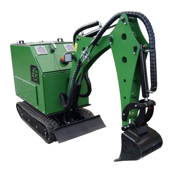
- Page 1 MULTIFUNCTIONAL MINI DIGGER SPRINGER-ECO Instruction MANUFACTURER: P.H.U. ELGO-PLUS ul. Przemysłowa 1 87-880 Brześć Kujawski POLAND Tel.: +48 602 841 094, +48 660 882 993 www.elgoplus.pl e-mail: kontakt@elgoplus.pl...
-
Page 2: Machine Features
1. Introduction This instruction contains basic informations of usage and terms of use mini digger SPRINGER-ECO. Proper maintenance and the correct way to use the machine condition the safe and reliable operation. The procedures described in this manual are the optimal methods of working with the machine and perform maintenance. - Page 3 2.1. General description The machine is designed for earthworks carried out in normal daylight conditions. If the machine is to be used for other purposes or have to work in a potentially hazardous environment, then follow the special safety regulations, and the machine itself should be equipped according to the working conditions.
- Page 4 2.2 Technical data Engine Tamel 3SG1 12M – 4PC Engine power 5,5 kW Supply voltage from net 3x400 VAC/N/PE (±10% tolerance) Frequency ((±2% 50 Hz tolerance) Battery power supply Lithium-ion battery Vanguard 10kWh (2x5kWh) Battery charger Vanguard 1050W Inverter InfiniSolar 3P 10 kW Type of steerage Remote –...
- Page 5 PIC 2.2 MINI DIGGER DIMENSIONS Important: Detailed information about power unit, batteries, batteries charger, inverter, wireless steering device are located in the instructions of these devices. 2.3. Equipment Ditch bucket (60cm wide)
-
Page 6: Safety Instructions
Bucket (20cm wide) Bucket (30cm wide) Teeth ripper tool 2.4. Additional equipment Demolition hammer 2.5. Name plate Name plate contains information such as: -CE marking - The name and address of the manufacturer - Machines model - Serial number - Year of production - Rated voltage 3. - Page 7 The operator should exercise extreme caution when working, all people nearby mini digger should still be within his sight. The power voltage supply have to match the specifiactions on the nameplate and in the documentation. Mini digger can be operated at the appropriate level of hydraulic oil. ...
- Page 8 Description of the marks on the machine Symbol draws attention to be extremy cautious when near working mini digger. Symbol indicates the location of the hydraulic oil drain valve. Symbol indicates that the element marked with this symbol contains circuits with 230VAC÷400VAC voltage. 4.
- Page 9 4.1. STEERING ELEMENTS The main control elements are the steering panel and the steering console; their description is below. PIC.4.1. STEERING PANEL Battery ignition switch Rotation dircetion switch (400 V network) Emergency shutdown button Indicator lights for phase control (power supply from the network) Indicator light for activation/charging of the battery (green) Indicator light indicating the system's readiness for operation (green) Indicator light confirming the 400V network connection...
- Page 10 PIC.4.2. STEERING CONSOLE Switch Activation button PIC.4.3. STEERING CONSOLE Lever to control the boom and rotation of the body Lever to control the position of the support Left track control lever Right track control lever Lever to control the position of the arm and the work of the bucket Turning on the lighting Emergency stop button Button that starts the hammer...
- Page 11 All plugs and other electrical components should be clean and dry when connecting them. Warning: Before performing any operation, check whether the voltage and frequency correspond to those on the nameplate and in the documentation. ELGO-PLUS is not responsible for connections inconsisten with the characteristics of the machine. Warning: Before starting, check if all switches are turned off and the safety buttons are pressed.
- Page 12 4.2.2 Starting the mini digger Below is the procedure for starting: 1. Connecting the 400V power cable The mini digger is equipped with a power socket located at the rear of the machine. The power plug should be connected to the machine's power socket. 2.
- Page 13 3. Battery activation Activating the battery is a recommended action to ensure the continuous operation of the mini excavator in the event of a temporary or continuous power outage from the 400V grid. Activation is performed by turning the battery switch "BATTERY" to the "ON" position. Below is a table outlining the behavior of the mini excavator during a power interruption, depending on the position of the battery switch.
- Page 14 PIC.4.4 Starting the 'Work Mode on 400V Electrical Grid Power'...
- Page 15 4.3. Work mode on battery power supply. Information: Before commencing work, it is essential to check the battery charge status. The battery charge level is displayed on the inverter screen under the top cover of the mini digger. Warning: Prior to starting, make sure that all switches are turned off, and safety buttons are released 4.3.1 Starting the mini digger.
- Page 16 3. Starting the steering console The same procedure as in the "Work Mode on 400V Electrical Grid Power". 4. Unlocking remote control The same procedure as in the "Work Mode on 400V Electrical Grid Power". PIC.4.5 Starting „Work mode on the battery power supply”...
- Page 17 4.3.2 Battery Charging Criteria The battery charge status can be checked on the inverter screen under the top cover of the mini digger. When the displayed voltage drops below 45V, it is recommended to commence battery charging. In cases where the stored energy in the batteries is not recharged, it will suffice for operation within a range of 20 to 40 minutes, depending on the load of the mini digger.
- Page 18 Information: Automatic cooling systems do not operate in the 230V power grid charging mode. Therefore, the top cover of the machine should be open during charging to ensure proper air circulation and heat dissipation. Warning: During charging, the mini digger must be protected from snow, rain, and other factors that may cause excessive moisture.
- Page 19 PIC. 4.7 Connecting to 230V power grid charging 4.5. Emergency stop and shutdown Warning: Emergency stopping and/or shutdown should be applied in every situation where the machine may cause harm to individuals or damage to nearby equipment. Warning: After an emergency stop and/or shutdown, do not restart the mini digger until the cause of the stoppage has been addressed, and ensure that the machine can operate safely.
- Page 20 4.5.1 Emergency shutdown button The emergency shutdown button is located on the mini digger's steering panel. Pressing it results in an immediate cutoff of electrical circuit power, leading to the complete shutdown of the machine. This button shuts down: the inverter power supply from the external grid, the power supply, radio receiver, lighting, ventilation, frequency converter, and the engine.
- Page 21 PIC.4.9 Restart after pressing the emergency stop button 4.5.5 Utilizing the Emergency Stop Button Function for Energy Saving The emergency stop button function can serve as a work pause when the mini digger is temporarily idle. This allows for energy conservation that would otherwise be consumed by the operation of the hydraulic drive engine system.
- Page 22 4.7. Solving problems Below are the issues that may occur during operation and their solutions. If the procedure described below proves ineffective or if other problems arise with the machine, contact the manufacturer. Problem Procedure System error Turn off the machine (see section 4.6). Wait for 30 seconds to allow all devices to Inverter suspension completely shut down.
- Page 23 PIC. 5.1. Control levers Control lever for boom extension and body rotation. Control lever for stabilizer position. Control lever for left track. Control lever for right track. Control lever for arm position and bucket operation. Below are the operations performed by the mini digger based on the movement of the levers. The symbol "N"...
- Page 24 Forward Movement Push both track control levers forward (C and D, PIC. 5.1) - the machine will move forward Reverse Movement Pull both track control levers backward (C and D, PIC. 5.1) - the machine will move backward. Left Turn Push the right track lever forward (D, PIC.
- Page 25 Operating 6.1. Visual and Audible Signals Visual Signals Before operating the mini digger, activate the signaling lamp (PIC. 6.1). The lamp is located at the front of the machine and is activated by pressing a button on its housing. After usage, remember to turn off the lamp.
- Page 26 6.2. Lighting To enhance workplace visibility, the mini digger is equipped with LED lighting consisting of two lamps. The lighting can be switched on and off using switches on the steering console (F, PIC. 5.3) and near the lamps (PIC. 6.3). PIC.6.3 Lighting 6.3.
- Page 27 When driving on flat terrain, retract the working equipment and raise it above the ground to avoid obstacles. When driving on uneven terrain, maneuver the machine to prevent tilting more than 10 degrees sideways. Ascending a slope If the tracks slip on an incline, press the bucket into the ground and pull the arm backward to assist the track drive in climbing the slope.
- Page 28 The mini digger is a versatile machine that can be equipped with various specialized working equipment to perform multiple types of tasks. Below are descriptions of only some operations. 6.8.1. Trench Digging Mount an appropriate bucket for this task. To work effectively, align the tracks with the direction of the trench being dug.
- Page 29 6.9. Machine Transport During machine transportation, adhere to applicable regulations concerning weight, width, height, length, and load securing. Remove grease, oil, mud, ice, etc., from access ramps and platform surfaces to prevent the machine from sliding. 6.10. Machine loading 1.Engage the transport vehicle's brakes. 2.Place chocks under the wheels of the transport vehicle.
- Page 30 Warning: Do not insert fingers into the holes to check their coaxiality, as it may lead to a serious accident. 6.Position the boom so that the mounting holes of the attachment align coaxially with the actuator holes. 7.Apply grease to the inner surface. 8.Insert the pins.
- Page 31 PIC.6.4. Attachment change Interchangable attachment Attachment actuator Pins with securing mechanism Quick couplers 6.12. Attaching the hammer (optional) Note: When attaching the hammer, apply the same safety principles as when replacing other attachments.
- Page 32 Attaching the hammer is done similarly to the other attachments, with the difference that you need to connect 2 quick couplers to power the hammer PIC.6.5 Attaching the hammer Hammer Quick coupler 1 Quick coupler 2 6.13 Before starting work Warning: Failure to comply with the following guidelines may lead to accidents, serious bodily harm, or death.
- Page 33 7. Operating Warning: A person who does not follow safety instructions and ignores the contained warnings must be certain that their working method is safe. Warning: Before engaging in operations related to operation, disconnect the machine from the electrical power source (unless necessary for these operations) and ensure there are no other hazards present on the machine.
- Page 34 PIC. 7.1. Lubrication and oil refill points Lubricating actuators and bushings Refilling hydraulic oil 7.2. Refilling hydraulic oil It is essential to maintain the correct level of hydraulic oil. The reservoir used is located under the flap of the mini digger and holds approximately 22 liters of oil. PIC.7.2.
- Page 35 7.3. Hydraulic Oil Change t is recommended to change the oil and oil filter once a year, assuming the machine operates for 8 hours a day. In justified cases, more frequent changes should be performed. The oil filter is located under the oil tank plug (B, PIC.
- Page 36 PIC.7.4 Track tension adjustment Adjustment screw 7.6. Replacement of brass bushings In the event of brass bushing wear, replace them with new ones. Remove the old bushings from the socket and install the new ones. PIC.7.5. Brass bushing Brass bushing Warning: When using a hammer to remove the bushings, metal fragments may detach and enter the eyes of the person performing the task.
- Page 37 Oil Tank Valve The hydraulic oil tank of the mini digger is equipped with a shut-off valve. This valve is used during hydraulic pump servicing and prevents oil leakage after disconnecting the hydraulic hose. To access the valve, unscrew the side cover of the mini digger. PIC.7.6 Side cover Side cover PIC.7.7 Oil tank valve...
- Page 38 7.8. Machine Maintenance Table 0.1. Regular Maintenance Every Use After first 5 Every 3 Every 6 hours months or months or 50 hours 100 hours Hydraulic oil Check level X(1) Replace Axles Check Screws Check/tighten Lubrication Perform x(or every 10h ) Electrical cables Check Check...
-
Page 39: Warranty Card
12.The warranty card is invalid without a date, stamp, and signature, as well as amendments and deletions made by unauthorized persons. 13.Matters not covered by these warranty terms are subject to the provisions of the Civil Code. Mini digger SPRINGER-ECO Purchase date:………………………………….. Serial number:…………………………….
Need help?
Do you have a question about the SPRINGER-ECO and is the answer not in the manual?
Questions and answers