Table of Contents

Related Manuals for Kärcher HD 3.7/35 Pb


Summary of Contents for Kärcher HD 3.7/35 Pb
- Page 1 OPERATOR’S MANUAL MODEL ORDER # HD 3.0/30 Pb 1.575-152.0 HD 3.7/35 Pb 1.575-154.0 HD 3.0/40 Pb 1.575-155.0 To locate your local Kärcher Commercial Pressure Washer Dealer nearest you, visit www.karchercommercial.com 9.807-623.0...
-
Page 2: Table Of Contents
CONTENTS Introduction & Important Safety Information .........3-4 Component Identification ................. 5 Assembly Instructions ................6 Operating Instructions................7-8 Detergents & Cleaning Techniques ............9 Shut Down and Clean-Up ..............10 Storage ....................10 Troubleshooting ..................11 Adjusting Unloader Valves ..............11 Preventative Maintenance .............. -
Page 3: Introduction & Important Safety Information
INTRODUCTION & IMPORTANT SAFETY INFORMATION Thank you for purchasing this Pressure Washer. WARNING: Risk of asphyxiation. WARNING Use this product only in a well We reserve the right to make changes at any time ventilated area. without incurring any obligation. 5. - Page 4 IMPORTANT SAFETY INFORMATION WARNING: Keep wand, hose, and WARNING: High pressure devel- WARNING WARNING water spray away from electric oped by these machines will wiring or fatal electric shock may cause personal injury or equip- result. ment damage. Keep clear of nozzle.
-
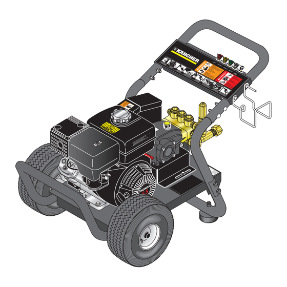
Page 5: Component Identification
COMPONENT IDENTIFICATION Unloader Pump Protector Pump Straight Through Wand Detergent Injector Inlet Screen Pressure Nozzle Garden Hose (not included) Starter Grip High Pressure Hose Detergent Bucket (not included) Pump — Develops high pressure. High Pressure Hose — Connect one end to water pump discharge nipple (detergent injector nipple) and Starter Grip—... -
Page 6: Assembly Instructions
ASSEMBLY INSTRUCTIONS Carriage Bolts Hose/Spray Gun Handle Bolt Storage Bracket Alignment Holes Washer Frame Assy. Studs STEP 1: Attach the handle to the STEP 2: Insert the carriage bolt STEP 3: Attach the spray gun/ frame of the pressure washer. Note: through the holes from the outside hose storage handle, and bracket It may be necessary to move the... -
Page 7: Operating Instructions
OPERATING INSTRUCTIONS Pump Oil Dipstick Engine Oil Dipstick Oil Window STEP 1: Check engine oil level. Oil level should be level with the bottom STEP 2: Remove shipping cap and of the oil filler neck. Be sure the machine is level when checking the oil install oil dipstick. - Page 8 OPERATING INSTRUCTIONS (CONT.) On-Off Switch STEP 7: Turn the engine switch to "On" position. STEP 8: Pull the starter grip. If the engine fails to start after 2 pulls, squeeze the trigger gun to release pressure On Briggs engines, move the throttle lever to "Fast" and repeat step.
-
Page 9: Detergents & Cleaning Techniques
DETERGENTS & GENERAL CLEANING TECHNIQUES THERMAL PUMP PROTECTION WARNING: Some detergents WARNING may be harmful if inhaled or If you run the engine on your pressure washer for ingested, causing severe nau- 1-2 minutes without pressing the trigger on the spray sea, fainting or poisoning. -
Page 10: Shutting Down And Clean-Up
SHUTTING DOWN AND CLEAN-UP On-Off Switch STEP 1: Remove detergent suc- STEP 2: Turn off the engine. STEP 3: Turn off wa- tion tube from container and insert ter supply. into one gallon of fresh water. Slide nozzle forward for low pressure or to connect black detergent nozzle into wand quick coupler. -
Page 11: Troubleshooting
TROUBLESHOOTING PROBLEM POSSIBLE CAUSE SOLUTION LOW OPERATING Faulty pressure gauge Install new gauge. PRESSURE Use larger supply hose; clean filter at Insufficient water supply water inlet. Match nozzle number to machine and/or Old, worn or incorrect spray nozzle replace with new nozzle. Belt slippage Tighten or replace;... -
Page 12: Preventative Maintenance
PREVENTATIVE MAINTENANCE This pressure washer was produced with the best available materials and quality craftsmanship. However, you as the owner have certain responsibilities for the correct care of the equipment. Attention to regular preventative maintenance procedures will assist in preserving the performance of your equipment. Contact your dealer for maintenance. -
Page 13: Models 152.0, 154.0,155.0 Exploded View
EXPLODED VIEW - 1.575-152.0,154.0,155.0 Pump 155.0 Pump 152.0 “Th ifor t con tain A Spa s che atin t Can tion g to Fire Fire y be rt Fire s Equ uire s Aro s or tion uire s or .”... -
Page 14: Models 152.0, 154.0, 155.0 Exploded View Parts List
EXPLODED VIEW PARTS LIST - 1.575-152.0,154.0,155.0 ITEM PART NO. DESCRIPTION ITEM PART NO. DESCRIPTION 8.706-955 Hose Barb, 1/4" Barb x 1/8" 9.802-064.0 Grommet, Rubber, ML Pipe, 90° Nozzle Holder (All Except 155.0 & 154.0) 8.925-057.0 Handle, Grab, Grey, OS 8.706-940.0 Hose Barb, 1/4" Barb x 1/8" 9.800-723.0 Label, Cold Water Handle ML Pipe (154.0) 9.803-126.0 Plate, Warning/Instruction, Black 1... - Page 15 EXPLODED VIEW PARTS LIST - 1.575-152.0,154.0,155.0 ITEM PART NO. DESCRIPTION 9.802-802.0 Washer, 1/4" Flat 9.802-773.0 Nut, 1/4" ESNA 8.718-980.0 Washer, 5/16" Flat 9.802-776.0 Nut, 5/16" ESNA 9.802-802.0 Washer, 1/4" Flat, SAE 9.802-741.0 Bolt, 8mm x 16mm Hex (152.0) 4 9.802-744.0 Bolt, 10mm x 20mm (154.0,155.0) 8.706 -860.0 Tee, 1/2"...
-
Page 16: Specifications
SPECIFICATIONS Pressure Nozzle Pump Unloader Engine Pump Pump Pulley Model (PSI) Size Pump Part No. Part No. Engine Part No. Pulley Part No. 1.575-152.0 3000 KB3030R 8.923-781.0 8.923-921.0 GX270 (270cc) 8.750-680.0 2BK80 9.802-389.0 1.575-154.0 3500 KM4035R.3 8.751-189.0 9.175-018.0 GX390 (390cc) 8.750-580.0 2BK90H 8.715-593.0... - Page 17 SPECIFICATIONS Pump Bushing Part Engine Pulley Engine Bushing Belt Belt Model Bushing Pulley Part No. Bushing Part No. Size Part No. 1.575-152.0 24MM 9.802-402.0 2BK40H 9.802-384.0 HX1" 9.802-398.0 BX38 (2) 9.802-417.0 1.575-154.0 24MM 9.802-402.0 2BK32H 9.802-381.0 HX1" 9.802-398.0 BX39 (2) 9.802-418.0 1.575-155.0 24MM...
-
Page 18: Hose & Spray Gun Assembly Parts List
HOSE & SPRAY GUN ASSEMBLY HOSE & SPRAY GUN ASSEMBLY PARTS LIST ITEM PART NO. DESCRIPTION 9.802-219.0 Wand Assy., Side Grip w/1/4" Coupler, 35-1/2" 4.775-054.0 EASYForce Advanced KNA 9.802-164.0 Coupler, 1/4” Female, Brass Nozzle, See Breakdown for Part Numbers 8.739-125.0 Hose, 3/8" x 50', 1 Wire, Tuff-Flex, (150.0, 151.0, 152.0) 8.739-203.0 Hose, 3/8"... -
Page 19: Vrt3 Unloader Exploded View And Parts List
VTR3 UNLOADER EXPLODED VIEW AND PARTS LIST VRT3 UnloadeR exploded View and paRTs lisT 8.750-300.0, 8 GPM, 4500 PSI EZ Start 8.750-300.0, 8 GPM, 4500 PSI EZ Start iTeM paRT no. desCRipTion 8.750-712.0 Outlet Fitting 8.750-713.0 Knob, Unloader 8.750-710.0 Repair Kit, VRT3, 4500 PSI (Kit Items: 1, 4, 8-12, 16, 21-22) Unloader adjustment procedures Remove lock nut (Item 19). -
Page 20: Uu1 Unloader Exploded View And Parts List
UU1 UNLOADER EXPLODED VIEW 9.175-018.0 UU1 3500PSI, UNIVERSAL UNLOADER (SPARE) UU1 UNLOADER EXPLODED VIEW PARTS LIST ITEM PART # DESCRIPTION KIT QTY ITEM PART # DESCRIPTION KIT QTY 8.751-394.0 Piston Housing 9.149-006.0 Sliding Connector Guide Piston C, D O-Ring Backup A, D 6 x 1.45 x 1.68 Piston O-Ring Back Up... -
Page 21: Vbt Unloader Exploded View And Parts List
VBT UNLOADER EXPLODED VIEW 8.754-696.0 UNLOADER, VBT BANJO 1/2M 3/8M, 3000PSI VBT UNLOADER EXPLODED VIEW PARTS LIST ITEM PART # DESCRIPTION KIT QTY ITEM PART # DESCRIPTION KIT QTY 8.754-929.0 Stem 9.803-914.0 Seal Washer 1/2) 8.754-937.0 Bypass Manifold 9.803-912.0 Backup Ring 8.754-930.0 O-ring, Ø2.62 x 6.02 9.802-892.0 Outlet Connector 3/8 MPT 8.730-882.0 Stem Connector... -
Page 22: Km.3 Pump Exploded View And Parts List
KM.3 SERIES PUMP EXPLODED VIEW 8.751-189.0 KM4035R.3 8.751-186.0 KM3540R.3 TORQUE SPECS Item # Ft.-lbs KM.3 SERIES PUMP EXPLODED VIEW PARTS LIST ITEM PART NO. DESCRIPTION 9.802-944.0 Hexagonal Screw 8.717-210.0 Closed Bearing 8.751-216.0 Crankcase Housing See Kits Below Plunger Oil seal 9.803-192.0 O-Ring Ø1.78 x 60.05 See Kits Below O-Ring Ø1.78 x 31.47... - Page 23 KM.3 SERIES PUMP EXPLODED VIEW PARTS LIST (CONT.) ITEM PART NO. DESCRIPTION 9.803-158.0 Connecting Rod 8.751-228.0 Connecting Rod Pin 9.803-218.0 Spring Washer 9.803-238.0 Connecting Rod Screw 70-060009 O-Ring, Ø2.62 x 126.67 8.751-229.0 Crankcase Cover 9.803-197.0 O-Ring, Ø1.78 x 14 9.803-202.0 Sight Glass 3/4 9.802-939.0 Cover Screw...
-
Page 24: Kb3030R Pump Exploded View And Parts List
KB3030R SERIES PUMP EXPLODED VIEW 8.923-781.0 KB3030R TORQUE SPECS Item # Ft.-lbs KB3030R SERIES PUMP EXPLODED VIEW PARTS LIST ITEM PART NO. DESCRIPTION ITEM PART NO. DESCRIPTION 8.754-841.0 Crankcase 9.803-198.0 Washer, Copper G3/8 8.754-846.0 O-ring Ø1.78 X 72.75 8.707-262.0 Plug, Brass G3/8 See Kits Below Plunger Oil Seal See Kits Below Valve Seat See Kits Below O-ring Ø1.78 X 26.7... - Page 25 KB3030R SERIES PUMP EXPLODED VIEW PARTS LIST ITEM PART NO. DESCRIPTION 8.754-855.0 Bolt, Plunger 8.754-092.0 Spacer, Copper 8.754-848.0 Plunger, 16 mm 9.803-962.0 Spacer, Copper 8.754-827.0 Plunger Rod 9.803-965.0 Connecting Rod Pin 9.803-966.0 Connecting Rod 9.803-218.0 Washer, 6 mm 8.933-020.0 Screw, Connecting Rod 8.754-847.0 O-ring Ø2.62 X 111.62 8.754-842.0...
- Page 26 www.karchercommercial.com Form # 9.807-623.0 • Revised 07/17 • Printed in U.S.A. or Mexico...
Need help?
Do you have a question about the HD 3.7/35 Pb and is the answer not in the manual?
Questions and answers