Advertisement
INSTALLATION & SERVICE
WANNER ENGINEERING, INC.
1204 Chestnut Avenue, Minneapolis, MN 55403
TEL: (612) 332-5681 FAX: (612) 332-6937
TOLL-FREE FAX [US only]: (800) 332-6812
www.hydra-cell.com
email: sales@wannereng.com
Document Fax Back System (510) 745-0440
D-35-SD
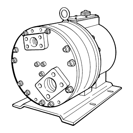
SLURRY DUTY PUMPS
D-35-SD WPR = 300 psi; G-35-SD WPR = 21 bar
G-35-SD
,
Advertisement
Table of Contents

Related Manuals for Wanner Engineering Hydra-Cell D-35-SD


Summary of Contents for Wanner Engineering Hydra-Cell D-35-SD
- Page 1 INSTALLATION & SERVICE D-35-SD G-35-SD SLURRY DUTY PUMPS WANNER ENGINEERING, INC. D-35-SD WPR = 300 psi; G-35-SD WPR = 21 bar 1204 Chestnut Avenue, Minneapolis, MN 55403 TEL: (612) 332-5681 FAX: (612) 332-6937 TOLL-FREE FAX [US only]: (800) 332-6812 www.hydra-cell.com email: sales@wannereng.com...
-
Page 2: Important Precautions
D-35-SD/G-35-SD Contents Page Installation ................2 Maintenance ................6 NOTE: The numbers in parentheses are the Reference Service (Fluid End) ..............7 Numbers on the illustrations in the Parts Manual. Service (Hydraulic End) ............13 Troubleshooting ..............17 D-35-SD/G-35-SD Installation Location Important Precautions Locate the pump as close to the supply source as possible. - Page 3 D-35-SD/G-35-SD Installation Hose Size and Routing Inlet Piping (Suction Feed) Size the suction line at least one size larger than the pump ° Caution: Do not pump at fluid temperatures above 120 inlet, and so that the velocity will not exceed 1 to 3 ft/sec (0.3 to °...
-
Page 4: Discharge Piping
D-35-SD/G-35-SD Installation Minimizing Acceleration Head and Frictional Losses Inlet Calculations To minimize the acceleration head and frictional losses: Acceleration Head • Keep inlet lines less than 3 ft (1 m) long • Use at least 2 in. (55 mm) I.D. inlet hose Calculating the Acceleration Head •... -
Page 5: Before Initial Start-Up
Use flexible hose between the pump and hard piping, to absorb Before Initial Start-Up vibration, expansion, or contraction. Before you start the pump, be sure that: Never install a shutoff valve in the discharge line between the pump and the regulator, or in the bypass line. •... - Page 6 Use the appropriate Wanner Hydra-Oil brand motor oil for the located above the supply tank, check the fluid supply level and application — contact Wanner Engineering if in doubt. replenish if too low. Caution: If you are losing oil but don’t see any external Caution: Protect the pump from freezing.
- Page 7 D-35-SD/G-35-SD Service (Fluid End)
-
Page 8: Tools And Supplies
D-35-SD/G-35-SD Service (Fluid End) Note: The numbers in parentheses are the Ref. Nos. on the Service Procedures illustrations in the Parts Manual. This section explains how to disassemble and inspect all easily- 1. Remove Inlet and Outlet serviceable parts of the pump. Repair procedures for the Adapters (49, 81) hydraulic end (oil reservoir) of the pump are included in a later section of the manual. - Page 9 D-35-SD/G-35-SD Service (Fluid End) Note: The valve seat remover tool must be tipped 3. Remove and Inspect Valve ° approximately 45 to get it through the seat bore. Assemblies (8-14, 41-45) Continue pressing or tapping, as required, until the spacer, crush seal, shell subassembly, spring, and valve Note: Wanner Repair Kits contain some or all of the fall out of the valve bore.
- Page 10 D-35-SD/G-35-SD Service (Fluid End) Reinstall the Valve Assemblies a. Clean the valve ports, shoulders, and O-ring grooves in the valve plate (17) with water or a compatible solvent. A ScotchBrite™ pad or brush may be used to abrade any old buildup or residue, but be careful not to scratch the plastic or wear away any of the plastic valve plate material.
- Page 11 D-35-SD/G-35-SD Service (Fluid End) the nose of the shell (43) presses into the inner diameter 4. Inspect and Replace of the crush seal (44). Use a 1.50-in.-diameter rod to Diaphragms (21) press down evenly on the shell subassembly to get the proper fit.
- Page 12 D-35-SD/G-35-SD Service (Fluid End) 5. Flush Contaminant from 7. Reinstall Valve Plate (17), Hydraulic End (only if a Manifold (4), and Manifold diaphragm has ruptured) Support (48) a. Remove the oil drain cap (36) and allow all oil and a. Reinstall the valve plate (17), with the valve assemblies contaminant to drain out.
- Page 13 D-35-SD/G-35-SD Service (Hydraulic End)
- Page 14 Kit (available end, at the 10 and 2 o’clock positions, to support the from Wanner Engineering or your local distributor). Refer parts as the pump is being disassembled. For additional...
- Page 15 (37) before reassembling any pistons or a. With the pump housing horizontal and mounted on the bearings into them. Contact Wanner Engineering to baseplate, insert the cam assembly (61) into the pump discuss replacement of the cylinder housing if there is housing.
- Page 16 D-35-SD/G-35-SD Service (Hydraulic End) f. Insert the five piston assemblies into the cylinder housing. c. Place a plunger on the exposed screw end of the plunger Visually inspect the small holes in the foot end of each guide lifter. The larger-diameter side of the plunger should piston to be sure that each ball (72) is in place.
- Page 17 D-35-SD/G-35-SD Troubleshooting Cavitation Pump Runs Rough • Inadequate fluid supply because: • Worn pump valves — Inlet line collapsed or clogged • Airlock in outlet system — Clogged line strainer • Oil level low — Inlet line too small or too long •...
- Page 18 D-35-SD/G-35-SD Troubleshooting Valve Wear Limited Warranty Wanner Engineering, Inc. extends to the original purchaser • Normal wear of equipment manufacturerd by it and bearing its name, a • Cavitation limited one-year warranty from the date of purchase against • Abrasives in the fluid defects in material or workmanship, provided that the •...
Need help?
Do you have a question about the Hydra-Cell D-35-SD and is the answer not in the manual?
Questions and answers