Advertisement
Quick Links
Installation, Operation & Maintenance
177-999H
T100 Series Medium Pressure
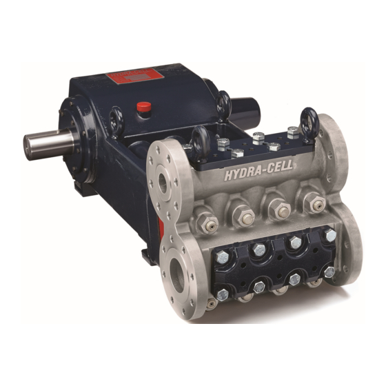
Models: T100K and T100M
W0499D
1204 Chestnut Avenue, Minneapolis, MN
T e l : ( 6 1 2 ) 3 3 2 - 5 6 8 1
F a x : ( 6 1 2 ) 3 3 2 - 6 9 3 7
Toll-free fax [US only]: (800) 332-6812
www.hydra-cell.com
email: sales@wannereng.com
55403
Advertisement

Related Manuals for Wanner Engineering Hydra-Cell T100 Series


Summary of Contents for Wanner Engineering Hydra-Cell T100 Series
- Page 1 Installation, Operation & Maintenance 177-999H T100 Series Medium Pressure Models: T100K and T100M W0499D 1204 Chestnut Avenue, Minneapolis, MN 55403 T e l : ( 6 1 2 ) 3 3 2 - 5 6 8 1 F a x : ( 6 1 2 ) 3 3 2 - 6 9 3 7 Toll-free fax [US only]: (800) 332-6812 www.hydra-cell.com email: sales@wannereng.com...
- Page 2 T100 Series Medium Pressure - Contents Page Component Identification Component Identification ............2 Specifications ................2 Dimensions ................4 Power End Installation ................8 Float Switch & Oil Fill Cap Sight Glass Maintenance ................11 with Dipstick Service (Fluid End) ..............12 Outlet Oil Fill Cap Service (Hydraulic Section) ...........13 Service (Power End) .............18 Troubleshooting ..............21...
- Page 3 T100 Series Medium - Specifications (Cont’d) Performance Net Positive Suction Head – NPSHr 189.0 50.0 184.0 47.0 178.0 5.25 172.0 44.0 166.0 160.0 500 psi (34 bar) 4.75 41.0 1500 psi (103 bar) 3000 psi (207 bar) 154.0 T100K 148.0 38.0 142.0 4.25...
- Page 4 T100 Series Medium Pressure - Dimensions Flange Version inches (mm) 4.83 Center of mass (123) 3.50 Minimum full key (89) 0.75 X 0.75 Keyway (19.05 X 19.05) W0543C 29.11 (739) Front View 2 X .06 18.54 (471) W0544D Ø 3.00 Top View (76.2) 177-999H...
- Page 5 T100 Series Medium - Dimensions (Cont’d) Flange Version inches (mm) ASME B16.5 43.00 3-1/2” CLASS 300 RF (1092) (8x 3/4-10 UNC-2B) Outlet Both Sides Center of mass ASME B16.5 1-1/2” CLASS 2500 RTJ (4x 1 1/8-7 UNC-2B) Outlet Both Sides 19.44 (494) 13.39...
- Page 6 T100 Series Medium Pressure - Dimensions NPT Version inches (mm) Center of mass 4.83 (123) 3.50 Minimum full key (89) 0.75 X 0.75 Keyway (19.05 X 19.05) W0507D 29.11 (739) Front View 2 X .18 16.00 (406) 15.65 (397) W0508D Ø...
- Page 7 T100 Series Medium - Dimensions (Cont’d) NPT Version inches (mm) 40.14 (1019) 2-1/2 NPT Intlet Both Sides Center of mass 1-1/2 NPT Outlet Both Sides 1/2-14 NPT 17.36 (441) 1/2-14 NPT 11.55 (293) 8.20 (208) 5.55 (141) W0509D 1/2-14 NPT 10.13 (257) 13.43...
- Page 8 Mounting vacuum at the pump outlet, allow atmospheric pressure at the outlet for 30 minutes before starting. Wanner Engineering recommends installing CAUTION: The pump shaft rotation direction is an outlet check valve with a 65 psi (4.5 bar) cracking pressure to prevent indicated by arrows on the pump housing.
- Page 9 If used, choose a top loading Consult installation drawing below for typical system components. basket. It should have a free-flow area of at least three times Contact Wanner Engineering or the distributor in your area for the free-flow area of the inlet. more details.
- Page 10 NPSHa = Pt + Hz - Hf - Ha - Pvp If there is a vacuum at the pump outlet, allow atmospheric pressure where: at the outlet for 30 minutes before starting. Wanner Engineering recommends installing an outlet check valve with a 65 psi cracking Pt = Atmospheric pressure pressure to prevent a vacuum condition during shutdown.
- Page 11 Change the oil after the first 500 hours of operation; New Hydra-Oil and then every 2000 hours or six months, whichever Wanner T100 Medium Pressure Tool Kit (see T100 Medium comes first. Pressure Tool Kit Parts) Note: Hydra-Cell T100 Series Pumps come standard with 10W30 motor oil. 177-999H...
- Page 12 T100 Series Medium - Fluid End Service This section explains how to disassemble and inspect all easily- discharge ports. Look for corrosion, scale and wear. If serviceable parts of the pump. wear is excessive, replace discharge retainer plate. Clean discharge retainer plates of any scale and corrosion with Note: The numbers in parentheses are the Reference Scotch-Brite™...
- Page 13 T100 Medium - Hydraulic Section Service Note: The numbers in parentheses are the Reference b. Remove the diaphragm (78) and diaphragm back-up Numbers shown in the Parts Section of the manual. ring (81). Inspect diaphragm carefully for any abnormal conditions. A ruptured diaphragm generally indicates a Hydraulic Section pumping system problem, and replacing only the diaphragm will not solve the larger problem.
- Page 14 T100 Medium - Hydraulic Section Service (Cont’d) Hydraulic Section Disassembly (Cont’d) Diaphragm Plate Disassembly WARNING: Manifold (84) and assembled parts weigh over 200 pounds (91 kg) and are a two man lift. Use care in handling to prevent personal injury or damage to equipment.
- Page 15 T100 Medium - Hydraulic Section Service (Cont’d) Airbleed Valve W0514B Underfill Valve Overfill Valve Valve Parts View 177-999H...
- Page 16 T100 Medium - Hydraulic Section Service (Cont’d) Hydraulic Section Assembly Diaphragm Assembly a. See Diaphragm Parts View. Diaphragm Plate Assembly CAUTION: It is important to observe the following steps d. and e. to ensure proper assembly. WARNING: Diaphragm plate (52) and assembled parts weigh over 100 pounds (45 kg) and are a two b.
- Page 17 T100 Medium - Hydraulic Section Service (Cont’d) Hydraulic Section Assembly (Cont’d) Eight hex nuts (26) W0516D Eight bolts (92) Torque sequence: - Snug eight hex nuts (26) in order indicated, then torque to 450 ft-lbs (610 N-m) in order indicated. - Repeat same snug and torque sequence for corresponding bolts (92) to 300 ft-lbs (407 N-m).
- Page 18 T100 Series Medium - Power End Service Power End Disassembly Crankshaft Removal a. Remove six cap screws (15) from one side of pump attaching WARNING: Crankcase (2) and assembled parts weigh seal and bearing assembly (assembled items 6, 7, 9, 11, 15, over 400 pounds (181 kg) and are a two man lift.
- Page 19 T100 Series Medium - Power End Service (Cont’d) Power End Assembly Crankshaft Installation WARNING: Crankcase (2) and assembled parts weigh a. Install one seal and bearing assembly to either side of over 400 pounds (181 kg) and are a two man lift. Use crankcase (2) using six screws (15).
- Page 20 T100 Series Medium - Power End Service (Cont’d) Power End Assembly (Cont’d) Float Switch Back Cover Assembly a. Align and assemble frame (44), gasket (43), sight glass (42), and thick gasket (41). Float Switch Back Cover Assembly b. Install eight screws (45) alternately through assembled frame into back cover (12) until snug.
- Page 21 T100 Series Medium Pressure - Troubleshooting Cavitation Pump Runs Rough • Inadequate fluid supply because: • Worn pump valves — Inlet line collapsed or clogged • Air lock in outlet system — Clogged line strainer • Oil level low — Inlet line too small or too long •...
- Page 22 T100 Series Medium - Torque Specifications Torque Specification Table for the T100K,M T100K,M Torque Specification Table Reference Number Torque Specification (N-m) Loctite No. Part Number Description 100 ft-lbs (136) 177-003-02 Bolts, Connecting Rod Assembly 300 ft-lbs (407) 177-059 Eyebolt, M20 12 ft-lbs (16) 177-048 Screw, Cap, hex-hd, M8, 25 mm...
- Page 23 T100 Series - Oil Level Monitor Oil Level Monitor Float Switch Note: The oil level should always be visible between the high and low oil marks viewed on sight glass (42). If the Conditions and Wiring Diagram oil level reaches the high or low mark, the float switch will be activated.
- Page 24 T100 Series Medium Pressure - Fluid End Parts W0499D Fluid End Outlet Valve Flange Version See Detail B Inlet Valve See Detail A Metalic Detail A NPT Version W0501E Metalic Detail B Note: for torque values refer to the Torque Specifications Table. 177-999H...
- Page 25 T100 Series Medium - Fluid End Parts (Cont’d) Ref. Quantity/ Ref. Quantity/ No. Part Number Description Pump No. Part Number Description Pump 14 177-059 Eyebolt, M20 ........2 103* 177-102-01 Valve Seat, 17-4 SST, HT .....3 177-102-02 Valve Seat, Hastelloy C ......3 26 177-152 Nut, Hex, M27 ........8 177-102-05...
- Page 26 T100 Series Medium - Hydraulic Section Parts W0499D Hydraulic Section Note: for torque values refer to the Torque Specifications Table. W0502C Rear View 177-999H...
- Page 27 T100 Medium - Hydraulic Section Parts (Cont’d) Ref. Quantity/ No. Part Number Description Pump 24 177-013 Gasket, Diaphragm plate ....1 177-101-02 Diaphragm Plate .........1 53 177-129-01 Cylinder, K ...........3 177-129-02 Cylinder, M ..........3 54 177-009 Spool, Valve ........3 55 177-117 Setscrew, M10, 10 mm ......2 56 G10-024-2010 Screw, Cap, soc-hd, M10, 90 mm ..2...
- Page 28 T100 Series Medium Pressure - Power End Parts W0499D Power End Note: for torque values refer to the Torque Specifications Table. 177-999H...
- Page 29 T100 Series Medium - Power End Parts (Cont’d) Ref. Quantity/ Ref. Quantity/ No. Part Number Description Pump No. Part Number Description Pump 31 177-036 Key, Crankshaft ........1 177-002-06 Crankshaft, Forged ......1 32 177-912 Dipstick ..........1 177-001-02 Crankcase ..........1 35 209-701 Fitting, 5/8 Tube ........1 177-003-02 Connecting Rod Assembly ....3...
- Page 30 T100 Series Medium - Tool Kit and Pump Storage T100 Medium Pressure Tool Kit Pump Storage for T100 Medium Pressure The T100 Medium Pressure Tool Kit (Part No. 177-800) contains the tools illustrated below. These tools are used to assist in CAUTION: If the pump is to be stored more than six months the repair and maintenance of the T100K and T100M.
- Page 31 T100 Medium - Replacement Parts Kits (Cont'd) TO ORDER REPLACEMENT PARTS KIT: A Replacement Parts Kit contains 11 digits corresponding to customer-specified design options. Order T100 Medium Pressure Kit D Contents Digit Code Description Pump Configuration Part Number * Description Quantity T100 For all T100 Series Pumps...
- Page 32 Minneapolis, MN 55403 USA recommendations and instructions of Wanner Engineering, Phone: 612-332-5681 ● Fax: 612-332-6937 Inc. Wanner Engineering, Inc. will repair or replace, at its Toll-Free Fax (USA): 800-332-6812 option, defective parts without charge if such parts are Email: sales@wannereng.com returned with transportation charges prepaid to Wanner www.Hydra-Cell.com...
Need help?
Do you have a question about the Hydra-Cell T100 Series and is the answer not in the manual?
Questions and answers