Table of Contents
Advertisement
Quick Links
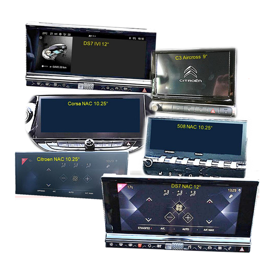
Compatible with
with 7inch, 8inch, 9inch, 10.25inch or 12.3inch monitor
Product features
1 x CVBS/AHD-input for rear-view camera
1 x CVBS/AHD-input for front camera
2 x CVBS/AHD-input for side-cameras or additional after-market video-sources
(e.g., USB-AV-player, DVB-T2 tuner, etc.)
All inputs NTSC and PAL compatible
Supported AHD resolutions 720p NTSC (30Hz), 720p PAL (25Hz), 960p NTSC (30Hz),
960p PAL (25Hz), 1080p NTSC (30Hz), 1080p PAL (25Hz)
HDV-NAC12 only:
IOS/Android, laptop, streaming stick, DVD-Player, DVB-T2 Tuner, etc.)
Supported HDMI resolutions 720p NTSC (60Hz), 720p PAL (50Hz),
1080p NTSC (60Hz), 1080p PAL (50Hz)
Automatic switching to rear-view camera input while reverse gear is engaged
Automatic front camera switching after reverse gear for 5, 10, 15 or 20 seconds
Adjustable guide lines (fixed or movable) can be activated for rear-view camera
(movable guide lines not available for all vehicles)
Activatable PDC graphic (not available for all vehicles)
Picture free during the car ride (only for inserted video-sources)
Version 15.08.2024
Video inserters
CI-HDV-NAC12 / CI-HDA-NAC12
Citroen, DS, Fiat, Opel, Peugeot
with NAC, RCC or IVI infotainment
and separate head-unit
1 HDMI-input for HD rear-view camera or additional HDMI-sources (e.g.,
from SW: GD V1.0/GW2A V1.0/RC
and
Toyota
vehicles
Attention!
Video signal type of each video
source must be selected in the
OSD menu of the
corresponding video input, if Auto
Detection has no function.
CI-HDV-NAC12 / CI-HDA-NAC12
Advertisement
Table of Contents

Related Manuals for Car-Interface CI-HDV-NAC12


Summary of Contents for Car-Interface CI-HDV-NAC12
- Page 1 Video inserters CI-HDV-NAC12 / CI-HDA-NAC12 Compatible with Citroen, DS, Fiat, Opel, Peugeot Toyota vehicles with NAC, RCC or IVI infotainment with 7inch, 8inch, 9inch, 10.25inch or 12.3inch monitor and separate head-unit Attention! Video signal type of each video source must be selected in the...
-
Page 2: Table Of Contents
Contents 1 Prior to installation Delivery contents Checking the compatibility of vehicle and accessories Limitations Warnings 1.4.1 NAC Head-Unit Versions Boxes and connectors - interface Settings - 8dip switch bench (interface functions) 1.6.1 Video inputs V1-Left and V2-Right (dip 1-2) 1.6.2 Front camera input V3-Front (dip 3) 1.6.3... -
Page 3: Legal Information
Legal Information By law, watching moving pictures while driving is prohibited, the driver must not be distracted. We do not accept any liability for material damage or personal injury resulting, directly or indirectly, from installation or operation of this product. Apart from using this product in an unmoved vehicle, it should only be used to display fixed menus (for example the MP3 menu of USB devices) or (rear-view) cameras’... -
Page 4: Checking The Compatibility Of Vehicle And Accessories
Requirements Brand Compatible vehicles Infotainments Berlingo3 (K9) from 09/2018 til 03/2024, C3 3.G from 01/2017 til 04/2024, C3 Aircross from 11/2017, C4 (N) from about 2017-05/2018, NAC or RCC with 7inch or 8inch touch C4 Cactus II from 01/2018 til 09/2020, screen. - Page 5 Brand Compatible vehicles Infotainments Combo E from 11/2018 til 11/2023, Corsa F from 07/2019, Navi 5.0 IntelliLink 8inch (NAC low Continental), Crossland X from model year 2017, Multimedia Radio 7inch (RCC Bosch), Grandland X from model year 2017, Multimedia Navi Pro 7inch and Multimedia Mokka B from 09/2020, 8inch Vivaro C from 03/2019,...
-
Page 6: Limitations
Limitations CAN-bus compatibility CAN-bus compatibility of interface may to some vehicles have no or limited compatibility. This can show on installation as well as later. Interface and all its video-inputs can be operated with analogue trigger signals, without connection to vehicle CAN-bus. Yet, in this case, some features do not work, see chapter 2.4.2 Analogue connection without CAN-bus. -
Page 7: Warnings
Warnings Damage to head-unit or interface can occur, if interface is installed to older SMEG or SMEG+ head-units (by Magneti Marelli). Damage can also occur if the 4-pin HSD connectors are connected incorrectly. Prior to installation the head-unit version must be identified. The very head-unit can differ in number and colours of the below pictures as there is sub-versions. -
Page 8: Boxes And Connectors - Interface
Boxes and connectors - interface The interface converts connected after-market sources’ video-signals into a video-signal compatible with the factory monitor. It can then be inserted, using separate trigger options. The interface also reads the vehicle’s CAN-bus signals and uses them for own functions. * HDMI-input only available on HDV-NAC12 Version 15.08.2024 from SW: GD V1.0/GW2A V1.0/RC... -
Page 9: Settings - 8Dip Switch Bench (Interface Functions)
Settings - 8dip switch bench (interface functions) Interface box, right side, black Dip position UP = OFF DOWN = Dip Function ON (down) OFF (up) Video 1 / V1-Left enabled disabled Video 2 / V2-Right enabled disabled Frontcamera / V3-Front enabled disabled Rear-view cam type (V4-Rear) -
Page 10: Rear-View Camera Settings (Dip 4)
1.6.3 Rear-view camera settings (dip 4) With dip 4 = OFF, the interface switches to factory picture while reverse gear is engaged, to display factory rear-view camera or factory optical park system picture. With dip 4 = ON, while the reverse gear is engaged the interface switches to its CVBS/AHD rear- view camera input V4-Reverse (provided that dip 5 is set to OFF) or to its... -
Page 11: Settings - 2Dip Switch Bench (Monitor Definition)
Settings - Interface box, top side, black 2dip switch bench (monitor definition) Attention: Opposite to other dip Monitor sizes Dip 1 Dip 2 benches (8dip and 4dip), the 2dip position here is UP = ON DOWN = 7inch, 8inch monitor OFF! 7inch, 8inch monitor with... - Page 12 Version 15.08.2024 from SW: GD V1.0/GW2A V1.0/RC HDV-NAC12 / HDA-NAC12...
-
Page 13: Installation
2 Installation For installation, first switch off the ignition and disconnect the vehicle’s battery following the instructions of the vehicle manufacturer regarding battery disconnection! If disconnecting battery is not suggested, enable vehicle sleep-mode (hibernation mode). In case the sleep-mode does not succeed, the disconnection of battery can be done with a resistor lead. -
Page 14: Connection Schema
Connection schema Version 15.08.2024 from SW: GD V1.0/GW2A V1.0/RC HDV-NAC12 / HDA-NAC12... -
Page 15: Connection - Picture Signal Cable
Connection - picture signal cable Connection - picture signal cable 2.3.1 NAC version head-unit (HSD) Attention! Do not connect to vehicle monitor damage to hardware! Connect waterblue female HSD+2 connector to waterblue male HSD+2 connector of interface. Disconnect single black female HSD connector of factory harness from rearside of head-unit and connect it to waterblue male HSD connector of picture signal cable. -
Page 16: Nac High Version (Double Hsd)
Connection - picture signal cable 2.3.2 NAC high version (double HSD) Remove the head-unit and disconnect white/black female double HSD connector from rear side. Attention! Do not connect to vehicle monitor damage to hardware! Connect single waterblue female HSD connector of the picture signal cable to the waterblue male HSD connector... -
Page 17: Ivi Und Rcc Versions
Connection - picture signal cable 2.3.3 IVI und RCC versions Attention! Do not connect to vehicle monitor damage to hardware! Connect waterblue female HSD+2 connector to waterblue male HSD+2 connector of interface. Disconnect black female HSD connector of factory harness at rear-side of head-unit and connect it to waterblue male HSD connector of picture signal cable. -
Page 18: Connection - Harnesses, Power Supply And Can-Bus Or Analogue Without Can-Bus
Connection – cable sets Connection – harnesses, power supply and CAN-bus or analogue without CAN-bus The interface can be integrated via CAN-bus as well as operated in analogue mode without CAN- bus connection. When integrated via CAN-bus, the interface is switched on by the vehicle CAN-bus and R-gear signal and turn signals are usually recognized. -
Page 19: Connection With Can-Bus
Connection - with CAN-bus 2.4.1 Connection with CAN-bus Connect grey wire 10pin power/CAN cable to vehicle’s CAN-low (see following chapters for place of connection). Connect blue wire 10pin power/CAN cable to vehicle’s CAN-high. (see following chapters for place of connection). Attention! If connecting to CAN-bus in combination with yellow wire to +12V BATT (terminal 30), it could... -
Page 20: Place Of Connection Power/Can - Nac And Rcc Head-Unit
Connection - with CAN-bus 2.4.1.1 Place of connection power/CAN - NAC and RCC head-unit Disconnect female PSA Quadlock connector at rear-side of head-unit and click-out green female 22pin section. Connect blue CAN-high wire, grey CAN-low wire and black GND wire of 10pin power/CAN cable to corresponding chambers of female 22pin section of factory harness. -
Page 21: Place Of Connection Power/Can - Ivi Head-Unit
Connection - with CAN-bus 2.4.1.2 Place of connection power/CAN - IVI head-unit Connect blue CAN-high wire grey CAN-low wire 10pin power/CAN cable corresponding chambers of black female 12pin connector of vehicle harness. There are two known vehicle pin definition variants displayed above. Tip: If CAN-bus is on chambers 4 and 10, chambers 5 and 11 are usually not occupied. -
Page 22: Analogue Connection Without Can-Bus
Connection - without CAN-bus 2.4.2 Analogue connection without CAN-bus On analogue connection, blue CAN-high wire grey CAN-low wire 10pin power/CAN cable are not connected. Connect purple wire Manual ACC 20pin interface cable +12V S-contact terminal 86s or ACC terminal 15r of vehicle (e.g., cigarette lighter, glove compartment illumination). -
Page 23: Power Supply Outputs
Power supply outputs Power supply outputs The two green power supply cables ACC out 12V (max 3A) CAM power 12V (max 3A) of the 20-pin interface cable can be used either as ACC power supply for external video-sources connected to the inputs V1-Left, V2-Right, V3-Front or HDMI-input* (e.g.,... - Page 24 Power supply outputs 2.5.1 Connection and power-supply - video-sources rear-view camera, front camera and 2 side-cameras Connect male RCA connector of rear-view camera to female RCA connector V4-Reverse 20pin interface cable. Connect male RCA connector of front camera to female RCA connector V3-Front 20pin interface...
-
Page 25: Connection And Power-Supply - Video-Sources Rear-View Camera, Front Camera And 2 Video- Sources
Power supply outputs 2.5.2 Connection and power-supply - video-sources rear-view camera, front camera and 2 video-sources Connect male RCA connector of rear-view camera to female RCA-connector V4-Reverse 20pin interface cable. Connect male RCA connector of front camera to female RCA-connector V3-Front 20pin interface... -
Page 26: After-Market Rear-View Camera
After-market rear-view camera After-market rear-view camera Automatic switching to rear-view camera is possible by CAN-bus or by analogue reverse signal. 2.6.1 Case 1: Reverse signal by CAN-bus Basic requirement is that the interface is connected to CAN-bus. Furthermore, vehicle CAN-bus reverse signal and its detection by the interface must be compatible. -
Page 27: Case 2: Reverse Signal Analogue Connection
After-market rear-view camera 2.6.2 Case 2: Reverse signal analogue connection If interface does not deliver +12V on green wire CAM power 12V (max 3A) 20pin interface cable when reverse gear is engaged (not all vehicles are compatible), an external switching signal from reverse gear light is required. -
Page 28: After-Market Front Camera
After-market front camera After-market front camera green wire CAM power 12V (max 3A) can be used to supply power to front camera (and all other cameras connected to the video inputs), as it only carries current for the duration of any camera activation (some cameras are not continuously current-stable). -
Page 29: After-Market Side-Cameras
After-market side-camera After-market side-cameras Side-cameras can be connected with switching by CAN-bus or analogue. 2.8.1 Case 1: Turn signal from CAN-bus Basic requirement is that the connection is made with CAN-bus. Furthermore, vehicle CAN-bus reverse signal and its detection must be compatible with the interface. If so, interface supplies +12V on green wire CAM power 12V (max 3A) 20pin interface cable... -
Page 30: Case 2: Turn Signal Analogue Connection
After-market side-camera 2.8.2 Case 2: Turn signal analogue connection With analogue connection, e.g., because signals from the vehicle CAN-bus are not recognised, the analogue switching is possible the two +12V trigger input wires Trig-Left and Trig-Right. For switching to the side-camera inputs, an external switching signal from the turn signal bulb is required. -
Page 31: Hdmi Rear-View Camera Or Other Hdmi-Source (Only Hdv-Nac12)
HDMI sources HDMI rear-view camera or other HDMI-source (only HDV-NAC12) HDMI-input* of the interface can generally be used for any video-source with HDMI-output, connected to it, e.g., rear-view camera, 360° camera-system or other video-source such as smartphones, laptop, streaming stick, DVB-T2 tuner, etc. If an optional HDMI video-source (e.g., smartphone, laptop, etc.) is connected to the HDMI-input*, the video shown on the display of the HDMI-source will be mirrored on the vehicle monitor. -
Page 32: Audio-Insertion
Audio insertion and external keypad 2.10 Audio-insertion The interface can only insert video-signals into the factory infotainment. Audio signals of the HDMI-input* are supplied through the 3.5 mm female jack connector HDMI-Audio out* of the interface. For all AV-sources connected to the interface, their audio output must be connected factory AUX input or an optional audio-inserter (e.g., AUX-UNI0x, FM modulator. -
Page 33: Osd-Menu Settings
OSD menu 2.12 OSD-menu settings Attention! Video signal type of each video source must be selected in the OSD menu of the corresponding video input, if Auto Detection has no function. OSD-menu settings can be changed by using the 3 keys on rear-side of interface. Pressing MENU key opens the OSD-menu or moves cursor to next menu item. - Page 34 OSD menu Menu V3 front Switch bench of 8 dip switches Dip 3 = ON Brightness Brightness Contrast Contrast Item H Horizontal image position Item V Vertical image position Trigger Type of selection of video input front. "Delay" function for front camera. The "Delay" setting is used to determine the automatic switching of a front camera connected to the V3 front input after reverse gear is engaged and...
- Page 35 OSD menu Guide Type Setting 6 different angles of the guide lines for the rear-view camera Moving guide lines Dynamic 1-6 Fixed guide lines Fixed 1-6 No guide lines Guide Pos. V Vertical position of the auxiliary wires 01-69 Guide L Pos.H Horizontal position of the left auxiliary wire 01-90 Guide R Pos.H...
-
Page 36: Interface Operation
3 Interface operation The external keypad of the can be used to switch all enabled inputs. Long press of keypad (2-3 seconds) Long press of external keypad (2-3 seconds), switches from factory video to inserted first enabled interface video-input. Any additional long press switches to the next enabled interface video-input and after last back to factory video. -
Page 37: Specifications
4 Specifications BATT/ACC range 9V - 16V Stand-by power drain about 3.4mA Power consumption 250mA @12V Video input 0.7V - 1V Video input signal types CVBS/AHD/HDMI (HDV-version only) Signal standards CVBS/AHD NTSC/PAL Temperature range -40°C to +85°C Dimensions video-box 115 x 25 x 109 mm (W x H x D) 5 FAQ - Troubleshooting interface functions - product-specific Problem Possible reasons... -
Page 38: Faq - Troubleshooting Interface Functions - General
6 FAQ - Troubleshooting Interface functions - general For any troubles which may occur, check the following table for a solution before requesting support from your vendor. Symptom Reason Possible solution Not all connectors have been reconnected to factory head- Connect missing connectors. - Page 39 Symptom Reason Possible solution Camera input picture Use relay or electronics to "clean" reverse gear lamp black. Camera power taken directly power. Alternatively, if CAN-bus box is compatible Camera input picture from reverse gear lamp. with the vehicle, camera power can be taken from green wire of 6pin to 8pin cable.
- Page 40 Version 15.08.2024 from SW: GD V1.0/GW2A V1.0/RC HDV-NAC12 / HDA-NAC12...
Need help?
Do you have a question about the CI-HDV-NAC12 and is the answer not in the manual?
Questions and answers