Table of Contents
Advertisement
Quick Links
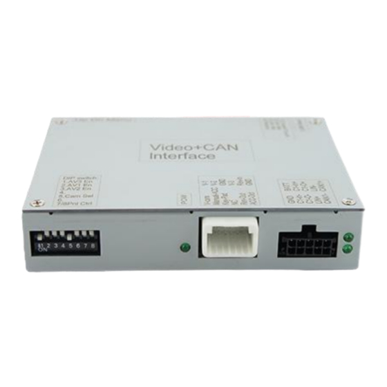
Video-inserter
CI-RL4-MBN4
Compatible with
Mercedes Benz
vehicles
with Comand APS HD NTG3, Comand APS NTG4,
Audio20 NTG4 and Audio50 APS NTG4 infotainment
with 10pin LVDS connector at the monitor
Video-inserter for front- and rear-view camera
and two additional video sources
Product features
Video-inserter for factory-infotainment systems
1 CVBS Input for rear-view camera
1 CVBS Input for front camera
2 CVBS Video-inputs for after-market Video sources (e.g. USB-Player, DVB-T Tuner)
Automatic switching to rear-view camera input on engagement of the reverse gear
Automatic front camera switching after reverse gear for 10 seconds
Video-in-motion (ONLY for connected video-sources)
Video-inputs NTSC and PAL compatible
Version 09.01.2023
HW CAM (V100) / (EF2L145/V20)
CI-RL4-MBN4
Advertisement
Table of Contents

Related Manuals for Car-Interface CI-RL4-MBN4


Summary of Contents for Car-Interface CI-RL4-MBN4
- Page 1 Video-inserter CI-RL4-MBN4 Compatible with Mercedes Benz vehicles with Comand APS HD NTG3, Comand APS NTG4, Audio20 NTG4 and Audio50 APS NTG4 infotainment with 10pin LVDS connector at the monitor Video-inserter for front- and rear-view camera and two additional video sources Product features ...
-
Page 2: Table Of Contents
Contents 1. Prior to installation 1.1. Delivery contents 1.2. Checking the interface compatibility of vehicle and accessories 1.3. Connectors - video interface 1.4. Dip-switch settings 1.4.1. Settigs of 8 dip – black 1.4.1.1. Activating the front camera input (dip 1) 1.4.1.2. -
Page 3: Prior To Installation
Legal Information By law, watching moving pictures while driving is prohibited, the driver must not be distracted. We do not accept any liability for material damage or personal injury resulting, directly or indirectly, from installation or operation of this product. This product should only be used while standing or to display fixed menus or rear-view-camera video when the vehicle is moving, for example the MP3 menu for DVD upgrades. -
Page 4: Checking The Interface Compatibility Of Vehicle And Accessories
1.2. Checking the compatibility of vehicle and accessories Requirements Brand Compatible vehicles Compatible systems C-class (W204) from 03/2007 till 02/2011, CL-class (C216) from 01/2006 till 05/2009, Comand APS HD NTG3 CLC-class (CL203) from 09/2008, Comand APS NTG4, E-class (W212) from 04/2009 till 05/2011, Audio20 NTG4, Mercedes-Benz E-class Coupe (W207) from 05/2009 till 05/2011,... -
Page 5: Connectors - Video Interface
1.3. Connectors - video-interface The video-interface (daughter PCB) converts the video signals of connected after-market sources in a factory monitor compatible picture signal which is inserted in the factory monitor, by using separate trigger options. 1.4. Dip-switch settings 1.4.1. Settings of 8 dip - black Some settings have to be selected by the dip-switches on the video interface. -
Page 6: Activating The Front Camera Input (Dip 1)
1.4.1.1. Activating the front camera input (dip 1) If set to ON, the interface switches for 10 seconds from the rear-view camera to the front camera input after having disengaged the reverse gear. In addition, a manual switch-over to the front camera input is possible via keypad (short press) from any image mode. Description of the front camera power supply: see chapter “Power supply output”. -
Page 7: Installation
2. Installation To install the interface, first switch off the ignition and disconnect the vehicle’s battery. Please read the owner`s manual of the car, regarding the battery`s disconnection! If required, enable the car`s Sleep-mode (hibernation mode) In case the sleep-mode does not succeed, the disconnection of the battery can be done with a resistor lead. -
Page 8: Connection Scheme
2.2. Connection scheme Version 09.01.2023 HW CAM (V100) / (EF2L145/V20) CI- RL4-MBN4... - Page 9 2.3. Connection – LVDS switch Connect the female 10pin connector “To interface” of the LVDS switch to the video interface’s male 10pin connector. Connect the female 10pin connector of the factory harness to the male 10pin connector “Monitor Cable In” of the LVDS switch (Pay attention to correct pin arrangement).
-
Page 10: Connection - 10Pin Power/Can Cable
Connection – 10pin Power / CAN cable Power and CAN must be connected to the quadlock on the back of the head unit! Cable colour Assignment ●● Red/Blue +12Volt Permanent 15 ● Brown Ground Pin 12 ●● Brown/Red CAN HIGH Pin 11 ●... -
Page 11: Analogue Power Supply
2.4. Analog power supply If the communication between the CAN box and the vehicle’s CAN bus does not succeed (not all vehicles are compatible), the analogue connection is required. Connect the female 12pin connector of the 12pin interface cable to the male 12pin connector of the video interface. -
Page 12: Power Supply Output
2.5. Power supply output The red power supply output ACC/front cam out 12V (max 3A) can be used to power an external source and has a different assignment, depending on the position of dip switch 1 (of 8 dips): Function Dip 1 ON +12V (max. -
Page 13: Connection - Video Sources
2.6. Connection – Video sources It is possible to connect an after-market rear-view camera, an after-market front camera and two more video sources to the video-interface. Before the final installation, we recommend a test-run to detect a incompatibility of vehicle and interface. Due to changes in the production of the vehicle manufacturer there’s always a possibility of incompatibility. -
Page 14: Audio Insertion
2.6.1. Audio insertion This interface is only able to insert video signals into the factory infotainment. If an AV- source is connected, the audio insertion has to be done by the factory audio AUX input or an FM-modulator. The inserted video-signal can be activated simultaneously to each audio- mode of the factory infotainment. -
Page 15: After-Market Rear-View Camera
2.6.3. After-market rear-view camera Some vehicles have a different reverse gear code on the CAN-bus which doesn’t communicate with the interface’s CAN. In this case there are two different ways of installation. If the interface’s CAN is able to detect an enabled vehicle’s reverse gear, the green wire of the 12pin cable should carry +12V while the reverse gear is engaged. -
Page 16: Case 2: Interface Does Not Receive The Reverse Gear Signal
2.6.3.2. Case 2: Interface does not receive the reverse gear signal If the video interface does not receive +12V on the green wire of the 12pin interface cable when reverse gear is engaged (not all vehicles are compatible), an external switching signal from the reverse gear light is required. -
Page 17: Connection - External Keypad
2.7. Connection – external keypad Connect the keypad’s female 4pin connector to the 12pin interface cable’s male 4pin connector. Note: Even if the switching through several video sources by the keypad mightn’t be required, the keypad’s invisible connection and availability is strongly recommended. Version 09.01.2023 HW CAM (V100) / (EF2L145/V20) CI- RL4-MBN4... -
Page 18: By Comand Buttons
3. Interface operation 3.1. By Comand buttons The knob of the Comand can be used to execute interface functions. Long pull back (3 sec.) knob in centre console to switch the video source. Each repetition will switch to the next enabled input. If all inputs are enabled the order is: ... -
Page 19: Picture Settings
4. Picture settings The picture settings are adjustable by the 3 push-buttons of the daughjter PCB’s menu keypad. Press the 1. button to open the OSD settings menu or to switch to the next menu item. By pressing the other both push buttons the selected value will be changed. To avoid accidental changes during or after the installation, we recommend to disconnect the keypad from the pushbutton cable after the adjustments are done. - Page 20 FAQ – Trouble shooting Interface functions For any troubles which may occur, check the following table for a solution before requesting support from your vendor. Symptom Reason Possible solution Not all connectors have been reconnected to factory head- Connect missing connectors. unit or monitor after installation.
- Page 21 Symptom Reason Possible solution Camera input picture Use relay or electronics to "clean" reverse gear lamp black. Camera power taken directly power. Alternatively, if CAN-bus box is compatible Camera input picture from reverse gear lamp. with the vehicle, camera power can be taken from green wire of 6pin to 8pin cable.
Need help?
Do you have a question about the CI-RL4-MBN4 and is the answer not in the manual?
Questions and answers