SMS TAKEDO-3VF TKN User Manual
Hide thumbs
Also See for TAKEDO-3VF TKN:
- User manual (75 pages) ,
- Instruction manual (17 pages) ,
- Instruction manual (14 pages)

Related Manuals for SMS TAKEDO-3VF TKN

Summary of Contents for SMS TAKEDO-3VF TKN
- Page 1 ® TAKEDO - 3VF USER MANUAL 17.11.2023 E. Castagnini REV. DATE Verification and approval R.T.
-
Page 2: Table Of Contents
INDEX 1 – INTRODUCTION ......................3 2 – WARNINGS AND CAUTIONS ..................3 3 – TECHNICAL DATA ...................... 4 4 – POWER CIRCUIT CONNECTION ................4 5 – LAYOUT ........................5 6 – APPLICATION DIAGRAM .................... 6 7 – KEYBOARD AND PROGRAMMING ................7 7.1 Status indications ...................... -
Page 3: Introduction
1 – INTRODUCTION TAKEDO-3VF TKN is a new inverter model with built-in EMC filter, compliant with Directives 2014/30/EU (Electromagnetic Compatibility) and 2014/35/EU (Low Voltage). The inverter can only operate in open loop. This manual contains essential information concerning the connections in the control panel and the operation of the inverter (keyboard operation, parameter list, alarm messages). -
Page 4: Technical Data
Current values are based on a temperature of 40°C, and a maximum switching frequency of 8kHz. For use in different conditions, please refer to the manufacturer's manual. BRAKING RESISTORS MINIMUM VALUE PROVIDED BY SMS DIMENSIONS CODE RECOMMENDED WxDxH (mm) () - (W) () -
Page 5: Layout
5 – LAYOUT Number Description Removable keypad Release opening (STO terminals below) Relay output terminals Control I/O terminals EMC filter screws and internal MOV varistor Braking resistor terminals +, BR Mains input terminals L1, L2, L3 Motor output terminals U, V, W Earth screw TAKEDO - 3VF USER MANUAL Revision 0 of 17.11.2023... -
Page 6: Application Diagram
6 – APPLICATION DIAGRAM TAKEDO - 3VF USER MANUAL Revision 0 of 17.11.2023... -
Page 7: Keyboard And Programming
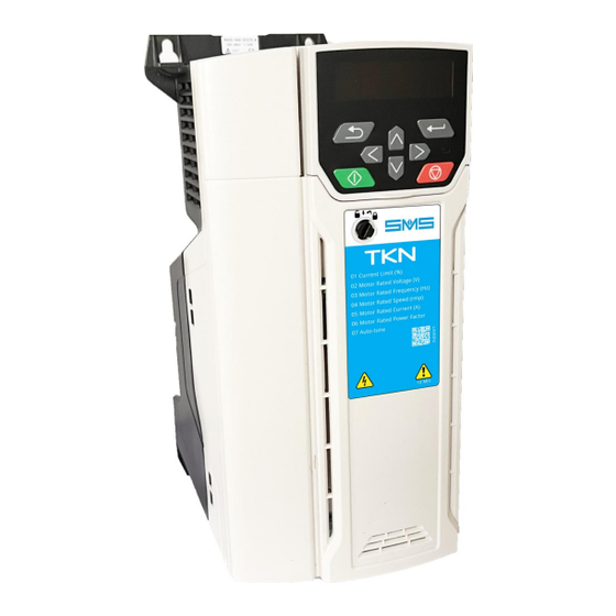
7 – KEYBOARD AND PROGRAMMING The keyboard and display provide information on the drive's operating status, alarms and alarm codes, and allow parameters to be changed and the drive to be reset in the event of an alarm. Detail of the TKN drive keyboard (1) The Enter key is used to access parameter display or editing mode, or to confirm a change made to a parameter. -
Page 8: Parameters Menu
8 – PARAMETERS MENU Parameter Description Default value Installation value 00.000 Takedo TKN 00.001 Current limit 180,0 % 00.002 Motor rated voltage 400 V 00.003 Motor rated frequency 50.00 Hz 00.004 Motor rated speed 1440.0 rpm 00.005 Motor rated current 13,50 A 00.006 Motor rated power factor... -
Page 9: Monitor Menu
Parameter Description Default value Installation value 00.070 Alarm 0 None 00.071 Alarm 1 None 00.072 Alarm 2 None 00.073 Alarm 3 None 00.074 Alarm 4 None 00.075 Alarm 5 None 00.076 Alarm 6 None 00.077 Alarm 7 None 00.078 Alarm 8 None 00.079 Alarm 9... -
Page 10: Diagnostics
11 – DIAGNOSTICS If a drive has a fault, users should not attempt to repair it, nor should they carry out any troubleshooting other than the diagnostic functions described in this chapter. WARNING 11.1 Fault indications Alarm code Condition Description The measured inertia exceeded The drive went into alarm during self-calibration Self-calibration... - Page 11 Alarm code Condition Description The alarm indicates a thermal overload of the motor based on the output current and the thermal time constant of the motor. The drive Output current overload timeout generates the Motor overheating alarm when the Motor overheating accumulator reaches 100%.
- Page 12 Alarm code Condition Description Loss of a motor phase Loss of a motor phase The loss of a phase at the drive output was detected detected. Output phase short Output phase short circuit Current overload detected at drive output when circuit enabled.
-
Page 13: Alarm Indications
The hardware alarm (HF01 -HF19) occurred and HF saved during the last shutdown the drive was switched off and on again. Contact SMS. RAM memory allocation error The Subarray RAM alarm indicates that the Subarray RAM derivative image of an option module required more parameter RAM than allowed. -
Page 14: Adjustments
12 – ADJUSTMENTS Before starting the system, the motor data must be set and the self-calibration must be carried out 12.1 Motor data setting Parameter 00.002 Motor rated voltage: Power supply voltage data read on plate Parameter 00.003 Motor rated frequency: Rated frequency data read on plate Parameter 00.004 Motor rated speed (rpm): Motor load rpm data - In case the rpm is not known, or 1500 rpm is indicated on the plate: ... -
Page 15: Speed Settings
12.4 Speed settings Parameter 00.010 Maximum frequency: Set the frequency to which the rated cabin speed corresponds Parameter 00.012 V1 Input Frequency 14: Set the frequency to which the rated cabin speed corresponds Parameter 00.013 V1 Input frequency 15: Set the frequency to which the speed of approach to the floor corresponds (normally 1/10 of the rated speed) Parameter 00.015 V1 Input frequency 16: Set the frequency to which the maintenance speed corresponds (Speed less than 0.63 m/sec) -
Page 16: Final Adjustments
12.7 Final adjustments After carrying out the above points, test the system and make the following checks and adjustments if necessary: IMPORTANT: Parameters must ALWAYS be changed ONE AT A TIME departure 1 - Adjust the via the parameters: JERK COUNTER-WHEEL ▲... -
Page 17: Dimensions, Weight And Fixings
13 - DIMENSIONS, WEIGHT AND FIXINGS Weight Ø Assembly Assembly Width Width Width Diameter 265 mm 277 mm 86 mm 115 mm 175 mm 6 mm 3.13 kg TAKEDO - 3VF USER MANUAL Revision 0 of 17.11.2023... - Page 18 TAKEDO - 3VF USER MANUAL Revision 0 of 17.11.2023...
Need help?
Do you have a question about the TAKEDO-3VF TKN and is the answer not in the manual?
Questions and answers