Table of Contents
Advertisement
Quick Links
Congratulations on owning a Scag mower! This manual contains the operating
instructions and safety information for your Scag mower. Reading this manual
can provide you with assistance in maintenance and adjustment procedures to
keep your mower performing to maximum efficiency. The specific models that
this book covers are listed on the inside cover. Before operating your machine,
please read all the information enclosed.
© 2023
Scag Power Equipment
Division of Metalcraft of Mayville, Inc.
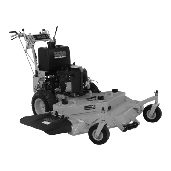
OPERATOR'S
MANUAL
SWZ
Walk-Behind
Model:
SWZ-36A-14FS
SWZ-48V-15FSE
SWZ-52V-18FSE
SWZ-14FSE-16
SWZ-15FSE-16
SWZL-52V-22FSE
SWZL-61V-22FSE
PART NO. 03542
PRINTED 09/2023
PRINTED IN USA
Advertisement
Table of Contents

Related Manuals for Scag Power Equipment SWZ-14FSE-16


Summary of Contents for Scag Power Equipment SWZ-14FSE-16
- Page 1 The specific models that this book covers are listed on the inside cover. Before operating your machine, please read all the information enclosed. © 2023 PART NO. 03542 Scag Power Equipment PRINTED 09/2023 Division of Metalcraft of Mayville, Inc. PRINTED IN USA...
- Page 2 W6100001 to W6199999 SWZ-48V-15FSE with a serial number of W6200001 to W6299999 SWZ-52V-18FSE with a serial number of W6300001 to W6399999 SWZ-14FSE-16 with a serial number of W6400001 to W6499999 SWZ-15FSE-16 with a serial number of W6500001 to W6599999 SWZL52V-22FSE...
-
Page 3: Table Of Contents
Table of Contents Table of Contents SECTION 1 - GENERAL INFORMATION ...................1 1.1 INTRODUCTION ............................1 1.2 DIRECTION REFERENCE .........................1 1.3 SERVICING THE ENGINE AND DRIVE TRAIN COMPONENTS ............1 1.4 SYMBOLS ..............................2 SECTION 2 - SAFETY INFORMATION ..................3 2.1 INTRODUCTION ............................3 2.2 SIGNAL WORDS ............................3 2.3 BEFORE OPERATION CONSIDERATIONS ....................3 2.4 TESTING THE SAFETY INTERLOCK SYSTEM ..................4... - Page 4 Table of Contents SECTION 6 - ADJUSTMENTS ....................20 6.1 PARKING BRAKE ADJUSTMENT ......................20 6.2 NEUTRAL ADJUSTMENT ........................20 6.3 STEERING CONTROL ROD ADJUSTMENTS ..................20 6.4 TRACKING ADJUSTMENT ........................21 6.5 THROTTLE CONTROL & CHOKE ADJUSTMENTS ................21 6.6 CUTTER DECK BELT ADJUSTMENTS ....................21 6.7 BELT ALIGNMENT ...........................22 6.8 ADJUSTING CUTTING HEIGHT ......................22 6.9 ELECTRIC CLUTCH ADJUSTMENT ......................25...
-
Page 5: Section 1 - General Information
Your mower was built to the highest standards in the Attachments and accessories manufactured by industry. However, the prolonged life and maximum companies other than Scag Power Equipment are not efficiency of your mower depends on you following the approved for use on this machine. See Section 8-1. Be... -
Page 6: Symbols
Section 1 1.4 SYMBOLS SYMBOL DESCRIPTION SYMBOL DESCRIPTION Choke Transmission Parking Brake Spinning Blade 48071S On/Start Spring Tension on Idler Off/Stop Falling Hazard Thrown Object Hazard Fast Slow Continuously Variable - Linear Cutting Element - Basic Symbol Pinch Point Cutting Element - Engage 481039S Hour meter/Elapsed Operating Hours Cutting Element - Disengage... -
Page 7: Section 2 - Safety Information
EACH EMPLOYEE THAT HAS READ THE MANUAL. CAUTION A replacement manual is available from your Authorized Scag Power Equipment Dealer or by contacting Scag Power Equipment, Service Department at P.O. Box 152, Mayville, WI 53050 or contact us via the Internet at www. -
Page 8: Testing The Safety Interlock System
Authorized Scag Power Equipment Dealer immediately to Wearing safety glasses, safety shoes and a have the safety interlock system repaired. -
Page 9: Operation Considerations
Section 2 2. Place the steering control levers in the neutral lock 3. To prevent tipping or loss of control, start and stop position, move the speed control lever out of the smoothly, avoid unnecessary turns and travel at neutral lock position, engage the parking brake, reduced speed. -
Page 10: Maintenance Considerations And Storage
Section 2 2.6 MAINTENANCE CONSIDERATIONS 15. Disengage power to the attachments when transporting or when not in use. AND STORAGE 16. The machine and attachments should be stopped 1. Never make adjustments to the machine with the and inspected for damage after striking a foreign engine running unless specifically instructed to do object, and damage should be repaired before so. -
Page 11: Using A Spark Arrestor
If you need service on your hydraulic system, please see your Authorized Scag Power Equipment Dealer. 13. Let the engine cool before storing. 14. DO NOT store the machine near an open flame. -
Page 12: Safety And Instructional Decals
Section 2 2.9 SAFETY AND INSTRUCTIONAL DECALS WARNING WARNING WARNING INSTALL BELT COVER BEFORE DO NOT OPERATE WITHOUT DISCHARGE CHUTE, MULCHING OPERATING MACHINE KIT, OR ENTIRE GRASS CATCHER INSTALLED READ OPERATOR'S MANUAL 483405 483402 483405 WARNING WARNING SPINNING BLADES ROTATING BLADES AND BELTS KEEP CLEAR * Keep hands, feet &... -
Page 13: Section 3 - Specifications
Section 3 SPECIFICATIONS 3.1 ENGINE General Type ....................Heavy Duty Industrial/Commercial Gasoline Brand ..................................Kawasaki Engine Model: (Scag Model SWZ-36A-14FS) ................... Kawasaki Model # FS481V (Scag Model SWZ-48V-15FSE) ..................Kawasaki Model # FS541V (Scag Model SWZ-52V-18FSE) ..................Kawasaki Model # FS600V (Scag Model SWZL-52V-22FSE, SWZL-61V-22FSE) ............Kawasaki Model # FS651V Displacement: Kawasaki FS481V ...............................603cc Kawasaki FS541V ...............................603cc... -
Page 14: Cutter Deck
Section 3 3.4 CUTTER DECK Type ........................Out-Front design with anti-scalp rollers Construction ....36 / 48 = 7-Gauge Deck Top w/10-Gauge Reinforced Spindle Area, 7-gauge (3/16") Deck Skirt 52 / 61 = 10-Gauge Deck Top w/10-Gauge Reinforced Spindle Area, 7-Gauge (3/16") Deck Skirt True Cutting Width: 36 .................................35.5"... -
Page 15: Section 4 - Operating Instructions
Section 4 OPERATING INSTRUCTIONS 2. Mower Deck Switch (Figure 4-1). Use to engage WARNING and disengage the mower drive system. Pulling up on the switch will engage the deck drive. Pushing down on the switch will disengage the deck drive. Do not attempt to operate this mower unless you 3. -
Page 16: Safety Interlock System
If the safety interlock system and 8 hours. does not operate as described below, contact your local Authorized Scag Power Equipment Dealer immediately to 2. Change the engine oil and oil filter after the first 20 have the safety interlock system repaired. -
Page 17: Starting The Engine
Section 4 4.5 STARTING THE ENGINE FORWARD TRAVEL To travel forward with the mower, release the parking brake, CAUTION select the desired speed using the speed control lever, pull steering control levers upward, release the neutral latch for both sides and slowly release both the left and right steering control levers. -
Page 18: Engaging The Deck Drive (Cutter Blades)
Section 4 4. Always operate the engine at full throttle to properly To travel in reverse, pull steering control levers upward. maintain cutting speed. If the engine starts to lug Keep the travel speed low while traveling in reverse. down, reduce the forward speed and allow the engine to operate at maximum RPM. -
Page 19: Removing Clogged Material
Section 4 4.12 MOVING MOWER WITH ENGINE - IMPORTANT - STOPPED Do not wash a hot or running engine. Cold water will damage the engine. Use compressed air to clean the engine if it is hot. To “free-wheel” or move the mower around without the engine running, turn the dump valve levers located on the 2. - Page 20 Section 4 3. Cut grass when it is dry and not too tall. Do not cut grass too short (cut off 1/3 or less of existing grass for best appearance). Mow frequently. 4. Keep mower and discharge chute clean. 5. When mowing wet or tall grass, mow the grass twice.
-
Page 21: Section 5 - Troubleshooting Cutting Conditions
Section 5 TROUBLESHOOTING CUTTING CONDITIONS CONDITION CAUSE CURE STRINGERS - OCCASIONAL Low engine RPM Run engine at full RPM BLADES OF UNCUT GRASS Ground speed too fast Slow speed to adjust for conditions Wet grass Cut grass after it has dried out Dull blades, incorrect sharpening Sharpen blades Deck plugged, grass accumulation... - Page 22 Section 5 TROUBLESHOOTING CUTTING CONDITIONS (CONT'D) CONDITION CAUSE CURE U N E V E N C U T O N F L AT Lift worn from blade Replace blade GROUND - WAVY HIGH-LOW APPEARANCE, SCALLOPED Blade upside down Mount with cutting edge toward ground CUT, OR ROUGH CONTOUR Deck plugged, grass accumulation Clean underside of deck...
- Page 23 Section 5 TROUBLESHOOTING CUTTING CONDITIONS (CONT'D) CONDITION CAUSE CURE SCALPING - BLADES HITTING Low tire pressures Check and adjust pressures D I R T O R C U T T I N G V E RY CLOSE TO THE GROUND Ground speed too fast Slow speed to adjust for conditions May need to reduce ground speed, raise...
-
Page 24: Section 6 - Adjustments
Section 6 ADJUSTMENTS 6.1 PARKING BRAKE ADJUSTMENT • Adjust the parking brake so that when the brake hand lever is against the stop on the handle bar, the brake levers on the brake shaft weldment are against the stops on the engine deck. CAUTION 482799 Figure 6-1. -
Page 25: Tracking Adjustment
Turn the tracking adjustment nut on the faster side clockwise until the machine tracks straight. CUTTER DECK DRIVE BELT TENSION 7. If tracking cannot be achieved, contact your ALIGNMENT IDLER - L.H. Authorized Scag Power Equipment Dealer. Figure 6-4. Deck Drive Belt Adjustment... -
Page 26: Belt Alignment
Section 6 -NOTE- There are two adjustments that can be made to the cutter deck, pitch and height. Due to initial belt stretch and to prevent the belt from slipping, check this adjustment after the first PITCH is the angle of the blades (comparing front to rear). 2 hours, 4 hours and 8 hours of operation. -
Page 27: Blade Height Adjustment
Section 6 BLADE HEIGHT ADJUSTMENT Adjusting the blade height can be done by moving any number of the five smaller 1/4" spacers on the blade mounting bolts to the top of the spindle shaft or below the spindle shaft. -NOTE- All blades should be positioned equally. -
Page 28: Custom-Cut Baffle Adjustment
Section 6 CUSTOM-CUT BAFFLE ADJUSTMENT To adjust the Custom-Cut Baffle height: 1. Place the cutter deck in the transport position. The Custom-Cut Baffle is designed to deliver optimum airflow and superior cutting performance in any type of 2. Remove the hardware securing the Custom-Cut grass. -
Page 29: Electric Clutch Adjustment
Section 6 6.9 ELECTRIC CLUTCH ADJUSTMENT ADJUSTMENT NUTS The electric clutch serves two functions in the operation of the mower. In addition to starting and stopping the power flow to the cutter blades, the clutch also acts as a brake to assist in stopping blade rotation when the PTO is switched off or the operator presence circuit is interrupted. -
Page 30: Section 7 - Maintenance
Section 7 MAINTENANCE 7.1 MAINTENANCE CHART - RECOMMENDED SERVICE INTERVALS HOURS PROCEDURE COMMENTS BREAK-IN 100 200 500 (FIRST 10) Check all hardware for tightness Check all belts for proper alignment See paragraph 7.6 Check all hydraulic fittings and See paragraph 2.5 hoses for leaks Check engine oil level See paragraph 7.3... - Page 31 Section 7 MAINTENANCE CHART - RECOMMENDED SERVICE INTERVALS (CONT'D) HOURS PROCEDURE COMMENTS BREAK-IN (FIRST 10) Check hardware for tightness Change engine oil filter See paragraph 7.4 Replace engine fuel filter See paragraph 7.5 Grease caster wheel pivot See paragraph 7.2 shafts Drain hydraulic system and See paragraph 7.3...
-
Page 32: Lubrication
Section 7 7.2 LUBRICATION GREASE FITTING LUBRICATION CHART NO. OF LOCATION LUBRICATION INTERVAL LUBRICANT PLACES 1 - Caster Wheel Pivot 100 Hours / Bi-Weekly Chassis Grease 2 - Caster Wheel Bearings 100 Hours / Monthly Chassis Grease 3 - Brake Actuator Levers 100 Hours / Bi-Weekly Chassis Grease 4 - Cutter Deck Spindles... -
Page 33: Hydraulic System
Section 7 7.3 HYDRAULIC SYSTEM A. CHECKING HYDRAULIC OIL LEVEL The hydraulic oil level should be checked after the first 8 hours of operation. Thereafter, check the oil after every Filter Head Hydraulic Oil 100 hours of machine operation or monthly, whichever Drain Cap occurs first. -
Page 34: Engine Oil
Section 7 7.4 ENGINE OIL A. CHECKING ENGINE CRANKCASE OIL FILLER NECK LEVEL INSERT The engine oil level should be checked after every 8 hours FUEL LEVEL of operation or daily as instructed in the Engine Operator’s Manual furnished with this mower. B. -
Page 35: Engine Air Cleaner
Section 7 7.7 BATTERY - ELECTRIC START 10. If fuel is spilled on clothing, change clothing immediately and wash affected skin. MODELS 11. Replace gas cap and tighten securely. For Low Emission (LE) and EPA Phase 3 (produced after WARNING 1/1/2011) models, tighten the fuel cap until it ratchets. -
Page 36: Cutter Blades
Section 7 A. CHARGING THE BATTERY WARNING Refer to the battery charger’s manual for specific instructions. Always wear proper hand and eye protection when working with cutter blades. Under normal conditions the engine’s alternator will have no problem keeping a charge on the battery. If the battery has been completely discharged for a long period of time, 2. -
Page 37: Blade Replacement
The cutter blades should be balanced to 1-1/2 oz-in. HEX NUT-TORQUE TO 75 LB-FT See your Authorized Scag Power Equipment Dealer for blade balancing or special tools, if you choose to balance your own blades. C. BLADE REPLACEMENT... -
Page 38: Section 8 - Illustrated Parts List
Section 8 ILLUSTRATED PARTS LIST 8.1 SCAG APPROVED ATTACHMENTS AND ACCESSORIES. Attachments and accessories manufactured by companies other than Scag Power Equipment are not approved for use on this machine. Scag approved attachments and accessories: Grass Catchers Scag Premium Lubricants... -
Page 39: Caster Assembly
Section 8 CASTER ASSEMBLY Ref. Part No. Description 04066-01 Quick Pin 43037-01 Spacer, Spacer Yoke, 1/2" Long 48100-01 Bronze Bearing 48114-04 Greasing Fitting 46082 Support Assembly (Incl. #3 & #4) 45006 Caster Yoke 04021-07 Nut, Elastic Stop 1/2-13 43022 Sleeve, Caster Wheel Bearing 04001-37 Bolt, Hex Head 1/2-13 x 5-1/2"... -
Page 40: Cutter Deck
Section 8 36A CUTTER DECK... - Page 41 Section 8 36A CUTTER DECK Ref. Ref. Part No. Description Part No. Description 04117-04 Nut, 1/2-13 Flange Elastic Stop 461848 Cutter Deck w/Decals 43277 Spacer, J-Hook 461663 Cutter Spindle Assembly 04041-12 Flatwasher, 3/8 x 1-1/2 x 16 GA 43312 Spacer, Outside 04021-09 Elastic Stop Nut, 3/8-16 481022...
-
Page 42: 52V Cutter Decks
Section 8 48V & 52V CUTTER DECKS 40 39... - Page 43 Section 8 48V & 52V CUTTER DECKS Ref. Ref. Part No. Description Part No. Description 04021-05 Nut, 3/8-16, Nut Centerlock 461852 Cutter Deck w/Decals 04019-04 Nut, 3/8-16, Serrated Flange 461855 Cutter Deck w/Decals 04021-09 Nut, 3/8-16 Elastic Stop 461992 Cutter Deck w/Decals 04004-02 Bolt, 5/16-18 x 1"...
-
Page 44: Cutter Deck
Section 8 61V CUTTER DECK 40 39... - Page 45 Section 8 61V CUTTER DECK Ref. Ref. Part No. Description Part No. Description 461091 Idler Arm Assy. (Incl. 62) 461860 Cutter Deck w/Decals 483176 Pad, Deck Wear 461663 Spindle Assembly 43028 J-Rod, Idler Pulley 43296 Spacer, Inside 43077 Spacer, J-Rod 482745 Pulley 04041-12...
-
Page 46: Engine Deck - Manual Start
Section 8 ENGINE DECK - MANUAL START ENGINE DECK - MANUAL START... - Page 47 Section 8 ENGINE DECK - MANUAL START Ref. Part No. Description 485014* Engine, Kawasaki 14FS (FS481V) 424620 Plate, Clutch Bracket 421370 Clutch Bracket 48030-09 Clamp 04003-04 Bolt, Carriage 5/16-18 x 1" 04021-10 Nut, 5/16-18 Elastic Stop 45418 Pulley Guard, 16" Small Frame 424661 Heatshield, 16"...
-
Page 48: Engine Deck - Electric Start
Section 8 ENGINE DECK - ELECTRIC START... - Page 49 Section 8 ENGINE DECK - ELECTRIC START Ref. Part No. Description 486754* Engine, Kawasaki FS15 (FS541V) 485326* Engine, Kawasaki FS18 (FS600V) 485017* Engine, Kawasaki FS22 (FS651V) 424620 Plate, Clutch Bracket 04030-04 Lock Washer 3/8" 04001-32 Bolt, Hex Head 3/8-16 x 1-1/4" 424661 Heatshield, 16"...
-
Page 50: Drive And Brake Components
Section 8 DRIVE AND BRAKE COMPONENTS 3, 3A 10, 10A 37 41... - Page 51 Section 8 DRIVE AND BRAKE COMPONENTS Ref. Part No. Description 481876 Ring, Split 04001-19 Bolt, 3/8-16 x 1" Hex Head 45842 Brake Shaft Assembly Weldment, 16" Small Frame 45854 Brake Shaft Assembly Weldment, 20" Large Frame 04062-01 Hair Pin Cotter, .094 x 1.62 04003-12 Carrage Bolt, 5/16-18 x .75"...
-
Page 52: Handle Assembly - Recoil Start
Section 8 HANDLE ASSEMBLY - RECOIL START 45 11... - Page 53 Section 8 HANDLE ASSEMBLY - RECOIL START Ref. Ref. Part No. Description Part No. Description 04063-07 Key, Woodruff, 3/16 x .75 463098 Upper Handle Wlmt. W/Decals 04001-59 Bolt, Hex Head, 1/4-20 x 1.25" 42675 Quadrant, Speed Control 04001-19 Bolt, Hex Head, 3/8-16 x 1" 04062-02 Hairpin, .094 x 1.19 45282...
-
Page 54: Handle Assembly - Electric Start
Section 8 HANDLE ASSEMBLY - ELECTRIC START 45 11... - Page 55 Section 8 HANDLE ASSEMBLY - ELECTRIC START Ref. Ref. Part No. Description Part No. Description 04063-07 Key, Woodruff, 3/16 x .75 463098 Upper Handle Wlmt, 16" Wide w/Decals 04001-59 Bolt, Hex Head, 1/4-20 x 1.25" 463099 Upper Handle Wlmt, 20" Wide w/Decals 04001-19 Bolt, Hex Head, 3/8-16 x 1"...
-
Page 56: Swz Fuel System
Section 8 SWZ FUEL SYSTEM Tank Purge To Fuel Pump To Engine Purge Port... - Page 57 Section 8 SWZ FUEL SYSTEM Ref. Part No. Description 463282 Fuel Tank Assembly (incl. #3, 4, 5, 6, 16, 17) 484286 Fuel Cap w/ Tether 484297 Fuel Cap w/Tethered - California Models Only (not shown) 484243 Fuel Gauge Assembly (incl. #4) 484242 Seal, Fuel Gauge 482571...
-
Page 58: Hydraulic Assembly
Section 8 HYDRAULIC ASSEMBLY... - Page 59 Section 8 HYDRAULIC ASSEMBLY Ref. Part No. Description 481164 Cap, Oil Reservoir 462773 Oil Reservoir (With Fittings) 482572 Fitting, 90 Degree - 3/8" Hose 48811 Hose, 3/8" ID - 10-1/4" Long (Order By The Inch) 48811 Hose, 3/8" ID - 7" Long (Order By The Inch) 48603-06 O-Ring 483097...
-
Page 60: Hydraulic Pump Assembly
Section 8 HYDRAULIC PUMP ASSEMBLY PORT "A" SIDE PORT "B" SIDE... - Page 61 Section 8 HYDRAULIC PUMP ASSEMBLY Ref. Part No. Description HG 70516 Housing Kit HG 70517 End Cap Kit HG 50641 Straight Headless Pin HG 50969 Hex Flange Bolt, M8-1.25 x 60mm HG 52629 Housing O-Ring HG 2513027 Charge Pump Kit HG 50273 Gerotor Assembly HG 9004101-1340...
-
Page 62: Wire Harnesses
Section 8 WIRE HARNESSES ENGINE DECK WIRE HARNESS CLUTCH PART NO. 484302 NEUTRAL INTERLOCK DIODE (600V 6A) GROUND BLACK W/RED STRIPE BLACK BLUE BLACK BLUE MAGNETO INSTRUMENT RECTIFIER WHITE PANEL HARNESS WHITE YELLOW BRAKE SWITCH HANDLE WIRE HARNESS - MANUAL START PART NO. - Page 63 Section 8 WIRE HARNESSES NEUTRAL INTERLOCK ENGINE DECK WIRE HARNESS ELECTRIC START GROUND PART NO. 487329 BLACK W/RED STRIPE GREEN BLACK BLACK BLUE BLUE CLUTCH INSTRUMENT WHITE PANEL HARNESS WHITE YELLOW RED W/YEL STRIPE DIODE (600V 6A) STARTER SOLENOID HANDLE WIRING HARNESS KAWASAKI ELECTRIC START PART NO.
-
Page 64: Swz Electrical Schematic - Recoil Start
Section 8 SWZ ELECTRICAL SCHEMATIC - RECOIL START (shown with Key off, PTO Off, Speed Control Lever in Neutral, OPC Disengaged) BRAKE OPERATOR SWITCH INTERLOCK Position PTO Switch Legend PRESENCE SWITCH SWITCH SWITCH ON (UP) DOWN (OFF) HOURMETER HANDLE BAR TO ENGINE DECK WIRE HARNESS CONNECTOR YELLOW... -
Page 65: Swz Electrical Schematic - Electric Start
Section 8 SWZ ELECTRICAL SCHEMATIC - ELECTRIC START (shown with Key off, PTO Off, Speed Control Lever in Neutral, OPC Disengaged) Position PTO Switch Legend BRAKE ON (UP) INTERLOCK Position Key Switch Legend SWITCH G + M + A B + L + A DOWN (OFF) SWITCH START... -
Page 66: Replacement Decals And Information Plates
Section 8 REPLACEMENT DECALS AND INFORMATION PLATES WARNING DO NOT OPERATE WITHOUT DISCHARGE CHUTE, MULCHING KIT, OR ENTIRE GRASS CATCHER INSTALLED WARNING SPINNING BLADES ROTATING BLADES AND BELTS KEEP CLEAR * Keep hands, feet & clothing clear * Keep all guards in place BLADE CONTACT &... -
Page 67: Replacement Decals And Information Plates
Section 8 REPLACEMENT DECALS AND INFORMATION PLATES 481423 482297 FAST Hea vy- Duty Comm e rcial OPERATOR’S 481971 MANUAL SPEED CONTROL SLOW 485527 NEUTRAL 481124 486136... -
Page 68: Replacement Decals And Information Plates
Section 8 REPLACEMENT DECALS AND INFORMATION PLATES Ref. Part No. Description 483405 Decal, Discharge Chute 48314 Decal, Scag Logo 483407 Decal, Danger-Spinning Blades 483406 Decal, Warning-Rotating Blades 482816 Decal, Height of Cut 485403 Decal, Metalcraft - USA 483402 Decal, Belt Cover 483404 Decal, Sulky Attachment 486117... - Page 69 Section 8...
-
Page 70: Limited Warranty - Commercial Equipment
Cutter decks are warranted against cracking for a period of three (3) years. (parts and labor 1st and 2nd year; parts only 3rd year.) The repair or replacement of the cutter deck will be at the option of Scag Power Equipment. We reserve the right to request compo- nents for evaluation. - Page 71 © 2023 Scag Power Equipment Division of Metalcraft of Mayville, Inc.
Need help?
Do you have a question about the SWZ-14FSE-16 and is the answer not in the manual?
Questions and answers