
Related Manuals for Asus AAEON BOXER-8658AI


Summary of Contents for Asus AAEON BOXER-8658AI
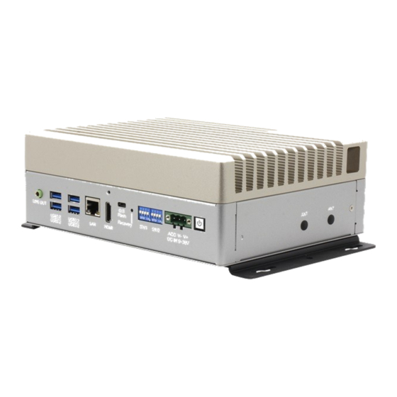
- Page 1 BOXER-8658AI AI@Edge Fanless PoE Embedded AI System with NVIDIA® Jetson Orin™ NX User’s Manual 1 Last Updated: June 4, 2024...
-
Page 2: Copyright Notice
Copyright Notice This document is copyrighted, 2024. All rights are reserved. The original manufacturer reserves the right to make improvements to the products described in this manual at any time without notice. No part of this manual may be reproduced, copied, translated, or transmitted in any form or by any means without the prior written permission of the original manufacturer. - Page 3 Acknowledgements All other products’ name or trademarks are properties of their respective owners. NVIDIA®, the NVIDIA logo, Jetson™, Jetson Orin™, and JetPack™ are ⚫ trademarks of the NVIDIA Corporation. Arm® and Arm®v8-M architecture are registered trademarks of Arm Limited. ⚫ Linux®...
- Page 4 Packing List Before setting up your product, please make sure the following items have been shipped: Item Quantity BOXER-8658AI ⚫ Wallmount Bracket ⚫ Screw Package ⚫ Power Connector ⚫ Power Adapter (Optional) ⚫ Power Cord (Optional) ⚫ If any of these items are missing or damaged, please contact your distributor or sales representative immediately.
- Page 5 About this Document This User’s Manual contains all the essential information, such as detailed descriptions and explanations on the product’s hardware and software features (if any), its specifications, dimensions, jumper/connector settings/definitions, and driver installation instructions (if any), to facilitate users in setting up their product. Users may refer to the product page at AAEON.com for the latest version of this document.
- Page 6 Safety Precautions Please read the following safety instructions carefully. It is advised that you keep this manual for future references All cautions and warnings on the device should be noted. All cables and adapters supplied by AAEON are certified and in accordance with the material safety laws and regulations of the country of sale.
- Page 7 As most electronic components are sensitive to static electrical charge, be sure to ground yourself to prevent static charge when installing the internal components. Use a grounding wrist strap and contain all electronic components in any static-shielded containers. If any of the following situations arises, please the contact our service personnel: Damaged power cord or plug Liquid intrusion to the device iii.
- Page 8 FCC Statement This device complies with Part 15 FCC Rules. Operation is subject to the following two conditions: (1) this device may not cause harmful interference, and (2) this device must accept any interference received including interference that may cause undesired operation.
- Page 9 China RoHS Requirements (CN) 产品中有毒有害物质或元素名称及含量 AAEON System QO4-381 Rev.A0 有毒有害物质或元素 部件名称 铅 汞 镉 六价铬 多溴联苯 多溴二苯 醚(PBDE) (Pb) (Hg) (Cd) (Cr(VI)) (PBB) 印刷电路板 × ○ ○ ○ ○ ○ 及其电子组件 外部信号 × ○ ○ ○ ○ ○ 连接器及线材 外壳 ○...
- Page 10 China RoHS Requirement (EN) Hazardous and Toxic Materials List AAEON System QO4-381 Rev.A0 Hazardous or Toxic Materials or Elements Component Name PCB and Components Wires & Connectors for Ext.Connections Chassis CPU & RAM HDD Drive LCD Module Optical Drive Touch Control Module Battery This form is prepared in compliance with the provisions of SJ/T 11364.
-
Page 11: Table Of Contents
Table of Contents Chapter 1 - Product Specifications..................1 Specifications ......................2 Chapter 2 – Hardware Information ..................5 Dimensions ....................... 6 Jumpers and Connectors ..................7 List of Jumpers ......................9 2.3.1 Jumper Settings ..................9 2.3.2 Vehicle MCU Control Setting (JP1) ............10 2.3.3 Front Panel (CN30) ................. - Page 12 2.4.17 Front Panel (CN30) ................28 2.4.18 UART for Debug Port (CN31) .............. 28 2.4.19 COM Port /8-Bit DIO Connector (CN32) ......... 29 2.4.20 Audio Panel Header (CN33)..............30 2.4.21 USB 2.0 Connector (CN35) ..............31 2.4.22 HDMI Port (CN36) .................. 31 2.4.23 UART/I2C for GPS/9-axis Sensor Board (CN38) ......
-
Page 13: Chapter 1 - Product Specifications
Chapter 1 Chapter 1 - Product Specifications... -
Page 14: Specifications
Specifications System AI Accelerator NVIDIA® Jetson Orin™ NX NVIDIA® Jetson Orin™ NX 8GB: 6-core Arm® Cortex®-A78AE v8.2 64-bit CPU NVIDIA® Jetson Orin™ NX 16GB: 8-core Arm® Cortex®-A78AE v8.2 64-bit CPU System Memory 8GB LPDDR5 16GB LPDDR5 Storage Device 2.5" SATA Drive Bay x 1 M.2 2280 M-Key x 1 (NVMe) Display Interface HDMI 2.0 (Type-A) x 1... - Page 15 System I/O Cont. Switch x 2 for ACC Ignition Delay On/Off Antenna x 7 TPM Support, GNSS Support, 9-Axis Sensor Support Expansion M.2 2230 E-Key x 1 (Wi-Fi/BT) M.2 3052 B-Key x 1 (LTE) M.2 2280 M-Key x 1 (NVMe) 2.5”...
- Page 16 Environmental Storage Temperature -40°F ~ 185°F (-40°C ~ 85°C) Storage Humidity 5 ~ 95% @ 40°C, non-condensing Anti-Vibration MIL-STD-810G, 514.6C Procedure 1, Category 4 Trucker/Semitrailer on US highway (Figure 514.6C-1-Category 4-Common carrier) Anti-Shock MIL-STD-810G, Method 516.6, Procedure I, flight vehicle equipment Certification CE/FCC Class A...
-
Page 17: Chapter 2 - Hardware Information
Chapter 2 Chapter 2 – Hardware Information... -
Page 18: Dimensions
Dimensions System Chapter 2 – Hardware Information... -
Page 19: Jumpers And Connectors
Jumpers and Connectors Note: For information regarding how to access the system’s PCBA, please see section 2.4. Chapter 2 – Hardware Information... - Page 20 Bottom Chapter 2 – Hardware Information...
-
Page 21: List Of Jumpers
List of Jumpers The board has a number of jumpers that allow you to configure your system to suit your application. The table below shows the function of each of the board's jumpers Label Function Vehicle MCU Control Setting CN30 Front Panel 2.3.1 Jumper Settings... -
Page 22: Vehicle Mcu Control Setting (Jp1)
2.3.2 Vehicle MCU Control Setting (JP1) Function ACC_ON_SET0 ACC_ON_SET1 ACC_ON_SET2 ACC_OFF_SET0 ACC_OFF_SET1 ACC_OFF_SET2 AT_ATX_SEL PWR12V_EN 3789_EN ACC ON Delay Setting Table Jumper Pin 5, 6 3, 4 1, 2 Delay Time OPEN OPEN OPEN 1 sec OPEN OPEN SHORT 3 sec OPEN SHORT OPEN... - Page 23 ACC OFF Delay Setting Table Jumper Pin 11, 12 9, 10 7, 8 Delay Time OPEN OPEN OPEN 1 min OPEN OPEN SHORT 3 min OPEN SHORT OPEN 5 min OPEN SHORT SHORT 10 min SHORT OPEN OPEN 30 min SHORT OPEN SHORT...
-
Page 24: Front Panel (Cn30)
2.3.3 Front Panel (CN30) Function Open AT (Default) Close ATX Chapter 2 – Hardware Information... -
Page 25: List Of Connectors
List of Connectors The board has a number of connectors that allow you to configure your system to suit your application. The table below shows the function of each of the board's connectors Label Function Jetson Orin NX Module Connector RTC Connector Micro USB for Flash Image CANBus Connector... - Page 26 Label Function CN38 UART/I2C for GPS/9 axis Sensor Board (optional) Switch for Vehicle MCU Setting Select Switch for Vehicle MCU Setting Select Switch for RS-232/RS422/RS-485 Select Recovery Switch Reset Switch Power Switch PWR1 SATA Power Connector Chapter 2 – Hardware Information...
-
Page 27: Jetson Orin Nx Module Connector (Cn1)
2.4.1 Jetson Orin NX Module Connector (CN1) Chapter 2 – Hardware Information... - Page 28 Chapter 2 – Hardware Information...
-
Page 29: Rtc Battery Connector (Cn2)
2.4.2 RTC Battery Connector (CN2) Signal 2.4.3 Micro USB for Flash Image (CN3) Signal VBUS Chapter 2 – Hardware Information... -
Page 30: Canbus Connector (Cn5)
2.4.4 CANBus Connector (CN5) Signal CAN0_L CAN0_H 2.4.5 LAN Port (CN8) ACT/LINK SPEED Signal Signal MDI0+ MDI0- MDI1+ MDI1- MDI2+ MDI2- MDI3+ MDI3- Chapter 2 – Hardware Information... -
Page 31: 2230 E-Key (Cn9)
2.4.6 M.2 2230 E-Key (CN9) Chapter 2 – Hardware Information... -
Page 32: 2280 M-Key (Cn10)
2.4.7 M.2 2280 M-Key (CN10) Chapter 2 – Hardware Information... - Page 33 Chapter 2 – Hardware Information...
-
Page 34: 3052 B-Key (Cn12)
2.4.8 M.2 3052 B-Key (CN12) Chapter 2 – Hardware Information... -
Page 35: Lan Port (Cn13)
2.4.9 LAN Port (CN13) Signal Signal MDI0+ MDI0- MDI1+ MDI1- MDI2+ MDI2- MDI3+ MDI3- 2.4.10 Audio Line Out (CN15) Signal Line_R Line_L Chapter 2 – Hardware Information... -
Page 36: Usb 3.2 Port (Cn17)
2.4.11 USB 3.2 Port (CN17) Signal Signal VBUS VBUS (A)D- (B)D- (A)D+ (B)D+ (A)SSRX- (B)SSRX- (A)SSRX+ (B)SSRX+ (A)SSTX- (B)SSTX- (A)SSTX+ (B)SSTX+ 2.4.12 SATA Connector (CN18) Signal Chapter 2 – Hardware Information... -
Page 37: Poe Port 1 ~ 8 (Cn19/Cn20/Cn21/Cn22)
Signal 2.4.13 PoE Port 1 ~ 8 (CN19/CN20/CN21/CN22) Pin Name Signal Type Signal Level MDI0+ DIFF MDI0- DIFF MDI1+ DIFF MDI2+ DIFF MDI2- DIFF MDI1- DIFF MDI3+ DIFF MDI3- DIFF Chapter 2 – Hardware Information... -
Page 38: Dc Power In Connector (Cn23)
2.4.14 DC Power in Connector (CN23) Signal PWR_IN ACC_IN 2.4.15 Fan Header (CN27) Signal VDD_12V FAN_TACH FAN_PWM_Q* Chapter 2 – Hardware Information... -
Page 39: Usb 3.2 Port (Cn29)
2.4.16 USB 3.2 Port (CN29) Signal Signal VBUS VBUS (A)D- (B)D- (A)D+ (B)D+ (A)SSRX- (B)SSRX- (A)SSRX+ (B)SSRX+ (A)SSTX- (B)SSTX- (A)SSTX+ (B)SSTX+ Chapter 2 – Hardware Information... -
Page 40: Front Panel (Cn30)
2.4.17 Front Panel (CN30) Signal Signal PWR_BTN* FORCE_RECOVERY* SYS_RST* BMCU_ACOK 3V3_AO VDD_5V_SYS 2.4.18 UART for Debug Port (CN31) Signal VDD_3V3_SYS UART2_TXD UART2_RXD Chapter 2 – Hardware Information... -
Page 41: Com Port /8-Bit Dio Connector (Cn32)
2.4.19 COM Port /8-Bit DIO Connector (CN32) RS-232 RS-422 RS-485 DIO1 DIO2 DIO3 DIO4 DIO5 DIO6 DIO7 DIO8 8-Bit DIO GPIO Index PQ.05 PG.06 PN.01 PH.00 PZ.06 PZ.05 Chapter 2 – Hardware Information... -
Page 42: Audio Panel Header (Cn33)
8-Bit DIO GPIO Index PZ.04 PZ.03 2.4.20 Audio Panel Header (CN33) Signal Signal MIC_L AGND MIC_R _RECOVERY* AUDIO_PRSNT_L HPOR_HDA MIC_HDA HPOL_HDA HP_HDA Chapter 2 – Hardware Information... -
Page 43: Usb 2.0 Connector (Cn35)
2.4.21 USB 2.0 Connector (CN35) Signal 2.4.22 HDMI Port (CN36) Signal Signal HDMI_DATA2_P HDMI_DATA2_N HDMI_DATA1_P HDMI_DATA1_N HDMI_DATA0_P HDMI_DATA0_N HDMI_CLK_P HDMI_CLK_N HDMI_SCL HDMI_SDA HDMI_PWR HDMI_HDP Chapter 2 – Hardware Information... -
Page 44: Uart/I2C For Gps/9-Axis Sensor Board (Cn38)
2.4.23 UART/I2C for GPS/9-axis Sensor Board (CN38) Signal 3.3V 3.3V I2C0_SCL I2C0_SDA GPIO UART_TXD UART_RXD Chapter 2 – Hardware Information... -
Page 45: Switch For Vehicle Mcu Setting Select (Sw1/Sw2)
2.4.24 Switch for Vehicle MCU Setting Select (SW1/SW2) Function Set Time ACC ON Delay Minutes Setting 1 Sec 3 Sec 5 Sec 10 Sec 15 Sec 20 Sec Chapter 2 – Hardware Information... - Page 46 Function Set Time ACC ON Delay Minutes Setting 25 Sec 30 Sec Function Set Time ACC OFF Delay Minutes Setting 1 min 3 min 5 min 10 min 30 min 60 min Chapter 2 – Hardware Information...
- Page 47 Function Set Time ACC OFF Delay Minutes Setting 120 min 0 min Function Set Time Power off AT/ATX Cut power source MODE Selection directly after ACC off delay time up Normal Power off after ACC off delay time up Function Set Time MCU Control Non MCU Control...
-
Page 48: Switch For Rs-232/Rs422/Rs-485 Select (Sw3)
2.4.25 Switch for RS-232/RS422/RS-485 Select (SW3) Mode 1T/1R RS-232 1T/1R RS-422 1T/1R RS-485 Low power shutdown 250kbps for RS-232 and RS-485/RS-422 RS-232 to 3Mbps and RS-485/RS-422 to 20Mbps Enable RS-422/RS-485 bias and termination resistors. Disable RS-422/RS-485 bias and termination resistors. 2.4.26 SATA Power Connector (PWR1) Signal... -
Page 49: Hardware Installation
Hardware Installation Before installing hard disk drives or expansion modules, ensure the system is powered down and disconnect the power cord from the system. 2.5.1 SATA Drive Installation Step 1: Open the chassis by removing the eight (8) bottom panel screws. Step 2: Affix the SATA drive to the drive bay using the four (4) screws provided. -
Page 50: Expansion Module Installation
2.5.2 Expansion Module Installation Install each expansion module by first inserting at an angle (approx. 30°), then gently press down and securing with the screws provided. Refer to the images below for guidance on M.2 Key slot location. Note: Make sure to affix the thermal bracket using three (3) screws, as shown below. To replace the bottom panel, simply reaffix using the eight (8) screws removed during step 1 of section 2.5.1. -
Page 51: Wall Mount Installation
2.5.3 Wall Mount Installation Secure the wall mount brackets to the chassis using the four (4) screws provided, as shown below. Chapter 2 – Hardware Information... -
Page 52: Chapter 3 - Bsp Flash Guide
Chapter 3 Chapter 3 – BSP Flash Guide... -
Page 53: Before Installation
Before Installation Before starting the process, make sure your BOXER-8658AI system is turned off and the power source is disconnected. You will need a Host PC running Ubuntu 18.04/20.04, and to make sure the NVIDIA Jetson Orin NX module is installed on the BOXER-8658AI carrier board system. -
Page 54: Connecting To Pc/Force Recovery Mode
Connecting to PC/Force Recovery Mode Step 1: On the Host computer, open the Linux terminal and enter the following command to extract the compressed BSP image files (BSP file name may vary): $ sudo tar -zxvf BOXER_8658AI_J5.1.2_A00_1.0.2_20231110.tar.gz Note: Do not decompress the file (Internal.tar.gz) using a Windows OS, BSP should only be decompressed in a Linux EXT3/4 file system. - Page 55 Note: Recovery mode cannot be initiated if the NVIDIA Jetson Orin NX module is disassembled. Ensure the NVIDIA Jetson Orin NX module is installed and refer to the image below to perform the force recovery mode steps: Chapter 3 – BSP Flash Guide...
-
Page 56: Flash Image To Board
Flash Image to Board Use the following steps to flash the OS to the BOXER-8658AI. Open terminal on the Ubuntu Host PC, then access the folder you extracted in the previous section. Enter the following command in terminal to flash the image: $ ./flashboxer -s 62517420 nvme Wait as the image is installed. -
Page 57: Check Bsp Version
Check BSP Version Once the flash image is successfully installed, the BOXER-8658AI will reboot automatically, then check the BSP version to see if the system is flashing the correct version of BSP . Open a Terminal, and type command “cat /proc/product”... -
Page 58: Chapter 4 - Os User Guide
Chapter 4 Chapter 4 – OS User Guide... -
Page 59: Introduction
Introduction The BOXER-8658AI’s OS, Ubuntu/Linux version, and preinstalled SDK components are as follows: Jetpack 5.1.2 (l4t 35.4.1) Ubuntu/Linux version Ubuntu version: 20.04.6 Kernel version: 5.10.120-tegra UEFI version: 4.1-33958178 Built-in all Jetson SDK Components CUDA Toolkit for L4T 11.4.19 cuDNN 8.6.0 TensorRT 8.5.2 OpenCV 4.5.4 VPI 2.3... -
Page 60: Update Note
Update Note Running $ sudo apt upgrade command in terminal will overwrite the Aaeon kernel device tree(.dtb)/kernel image(Image)/bootloader in the OS, which can lead to unexpected results, including the loss of I/O ports. To prevent this, AAEON disables the NVIDIA apt repository by default for updating NVIDIA apt packages. AAEON maintains updated versions of BSP on the product page, which follow updates to the NVIDIA Jetpack software. -
Page 61: Power Mode For Boxer-8658Ai
Power Mode for BOXER-8658AI NVIDIA Jetson Orin NX power mode can be selected and monitored by GUI, please refer to the following image: Note: Power mode is dependent on DRAM size. For more detailed information please visit: https://developer.nvidia.com/embedded/jetson-modules Chapter 4 – OS User Guide... -
Page 62: Dio/Gpio Setting Command For Boxer-8658Ai
DIO/GPIO Setting Command for BOXER-8658AI GPIO test command: Please refer to HW DIO/GPIO section for PIN Number and GPIO ID mapping. Take “PIN 6 <-> GPIO ID:PQ.05” as an example on JetPack 5.1.2: # Export PQ.05 $ echo PQ.05 > /sys/class/gpio/export # Set GPIO direction to output mode $ echo "out"... - Page 63 FAN PWM control command: Stop NV fan control daemon $ sudo systemctl stop nvfancontrol Set PWM value $ echo [PWM_duty_cycle] > /sys/devices/platform/pwm-fan/hwmon/hwmon<x>/pwm1 * Where: [PWM_duty_cycle] is a value in the range [0, 255]. <x> is a kernel enumerated number for fan hwmon. Chapter 4 –...
Need help?
Do you have a question about the AAEON BOXER-8658AI and is the answer not in the manual?
Questions and answers