
Related Manuals for Asus AAEON FWS-7850


Summary of Contents for Asus AAEON FWS-7850
- Page 1 FWS-7850 Rackmount Network Appliance User’s Manual 1 Last Updated: June 28, 2024...
-
Page 2: Copyright Notice
Copyright Notice This document is copyrighted, 2024. All rights are reserved. The original manufacturer reserves the right to make improvements to the products described in this manual at any time without notice. No part of this manual may be reproduced, copied, translated, or transmitted in any form or by any means without the prior written permission of the original manufacturer. - Page 3 Acknowledgement All other products’ name or trademarks are properties of their respective owners. Intel® is a registered trademark of Intel Corporation ⚫ Intel® Core™ is a trademark of Intel Corporation ⚫ ITE is a trademark of Integrated Technology Express, Inc. ⚫...
- Page 4 Packing List Before setting up your product, please make sure the following items have been shipped: Item Quantity FWS-7850 ⚫ If any of these items are missing or damaged, please contact your distributor or sales representative immediately. Preface...
- Page 5 About this Document This User’s Manual contains all the essential information, such as detailed descriptions and explanations on the product’s hardware and software features (if any), its specifications, dimensions, jumper/connector settings/definitions, and driver installation instructions (if any), to facilitate users in setting up their product. Users may refer to the product page at AAEON.com for the latest version of this document.
- Page 6 Safety Precautions Please read the following safety instructions carefully. It is advised that you keep this manual for future references All cautions and warnings on the device should be noted. All cables and adapters supplied by AAEON are certified and in accordance with the material safety laws and regulations of the country of sale.
- Page 7 As most electronic components are sensitive to static electrical charge, be sure to ground yourself to prevent static charge when installing the internal components. Use a grounding wrist strap and contain all electronic components in any static-shielded containers. If any of the following situations arises, please the contact our service personnel: Damaged power cord or plug Liquid intrusion to the device iii.
- Page 8 FCC Statement This device complies with Part 15 FCC Rules. Operation is subject to the following two conditions: (1) this device may not cause harmful interference, and (2) this device must accept any interference received including interference that may cause undesired operation.
- Page 9 China RoHS Requirements (CN) 产品中有毒有害物质或元素名称及含量 AAEON System QO4-381 Rev.A0 有毒有害物质或元素 部件名称 铅 汞 镉 六价铬 多溴联苯 多溴二苯 醚(PBDE) (Pb) (Hg) (Cd) (Cr(VI)) (PBB) 印刷电路板 × ○ ○ ○ ○ ○ 及其电子组件 外部信号 × ○ ○ ○ ○ ○ 连接器及线材 ○ ○...
- Page 10 China RoHS Requirement (EN) Hazardous and Toxic Materials List AAEON System QO4-381 Rev.A0 Hazardous or Toxic Materials or Elements Component Name PCB and Components Wires & Connectors for Ext.Connections Chassis CPU & RAM HDD Drive LCD Module Optical Drive Touch Control Module Battery This form is prepared in compliance with the provisions of SJ/T 11364.
-
Page 11: Table Of Contents
Table of Contents Chapter 1 - Product Specifications..................1 Specifications ......................2 Chapter 2 – Hardware Information ..................5 Dimensions ....................... 6 2.1.1 FWS-7850 System ..................6 2.1.2 FWS-7850 Main Board ................7 2.1.3 PER-T675 Riser Card ................... 9 2.1.4 PER-T682 I/O Board ................... - Page 12 AMI BIOS Setup ..................... 39 Setup Submenu: Main ..................40 Setup Submenu: Advanced ..................41 3.4.1 Trusted Computing ..................42 3.4.2 CPU Configuration ..................44 3.4.2.1 Efficient-core Information ............... 45 3.4.2.2 Performance-core Information ............46 3.4.3 PCH-FW Configuration ................47 3.4.3.1 Firmware Update Configuration ............
- Page 13 3.5.4 VMD Setup Menu ..................72 3.5.5 PCH-IO Configuration ................73 3.5.6 SATA Configuration ................... 74 Setup Submenu: Security ..................75 3.6.1 Secure Boot ....................76 3.6.1.1 Key Management ................77 Setup Submenu: Boot ..................79 Setup Submenu: Save & Exit ................80 Appendix A –...
-
Page 14: Chapter 1 - Product Specifications
Chapter 1 Chapter 1 - Product Specifications... -
Page 15: Specifications
Specifications System Form Factor 1U Rackmount Network Appliance Processor 12th/13th Generation Intel® Core™ Processors Chipset Intel® W680 Chipset System Memory DDR5 U-DIMM x 4, up to 128GB (ECC) Network Ethernet 10GbE SFP+ x 2 (Intel® Ethernet Controller X710-BM2 x 1) Bypass Dependent NIM Slot... - Page 16 Miscellaneous Internal RTC Watchdog Timer 1~255 Software Button TPM 2.0 SPI GPIO Reserve Internal Pin Header 8-bit Digital I/O interface (4-in/4-out) Smart Fan x 3 Optional System Fan x 1 MTBF (Hours) Color Black Environmental Parameters and Dimension Power Requirement 1U 300W Redundant PSU x 1 Operating Temperature 32°F ~ 104°F (0°C ~ 40°C)
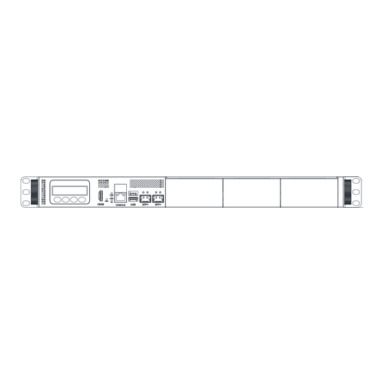
- Page 17 Front Panel 10GbE SFP+ x 2 Power LED x 1 Status LED x 1 HDD Active LED x 1 USB 3.2 Gen 1 x 2 HDMI x 1 RJ-45 Console x 1 LCM Display with Keypad x 1 Software Programmable Button x 1 NIM Slot x 3 Rear Panel AC Power Input x 1...
-
Page 18: Chapter 2 - Hardware Information
Chapter 2 Chapter 2 – Hardware Information... -
Page 19: Dimensions
Dimensions 2.1.1 FWS-7850 System Chapter 2 – Hardware Information... -
Page 20: Fws-7850 Main Board
2.1.2 FWS-7850 Main Board Component Side Chapter 2 – Hardware Information... - Page 21 Main Board Solder Side Chapter 2 – Hardware Information...
-
Page 22: Per-T675 Riser Card
2.1.3 PER-T675 Riser Card Chapter 2 – Hardware Information... -
Page 23: Per-T682 I/O Board
2.1.4 PER-T682 I/O Board Top Side Chapter 2 – Hardware Information... - Page 24 Bottom Side Chapter 2 – Hardware Information...
-
Page 25: Jumpers And Connectors
Jumpers and Connectors 2.2.1 FWS-7850 Main Board Component Side Chapter 2 – Hardware Information... -
Page 26: Per-T675 Riser Card
2.2.2 PER-T675 Riser Card Chapter 2 – Hardware Information... -
Page 27: Per-T682 I/O Board
2.2.3 PER-T682 I/O Board Chapter 2 – Hardware Information... -
Page 28: List Of Jumpers
List of Jumpers The FWS-7850 system board is equipped with a number of jumpers which can be configured for your application. This section details those jumpers and their settings. Label Function Clear ME & Clear CMOS 2.3.1 Clear CMOS Normal Clear CMOS Clear ME Chapter 2 –... -
Page 29: List Of Connectors
List of Connectors The FWS-7850 system board is equipped with a number of connectors which can be used for configuring your system and connecting with external modules. This section details those connectors and settings. Label Function CN12 CPU Fan CN10 CPU Fan CN36 System Fan 1... -
Page 30: Front Panel Header (Fp1)
2.4.1 Front Panel Header (FP1) Signal Type Signal Type PANSWH+ SYS_RESET+ EXT_PWRLED+ EXT_HDDACT+ SATALED- 2.4.2 DIO Pin Header (CN8) Signal Type Signal Type DII1 DIO1 DII2 DIO2 DII3 DIO3 DII4 DIO4 +V5S Chapter 2 – Hardware Information... -
Page 31: Case Open Header (Cn9)
2.4.3 Case Open Header (CN9) Signal Type Signal Type COPEN+ Chapter 2 – Hardware Information... -
Page 32: Left Front 2.5" Hdd Installation
Left Front 2.5” HDD Installation Step 1: Unscrew the upper lid of the chassis. Step 2: Lock HDD on the HDD bracket with eight (8) screws. Chapter 2 – Hardware Information... - Page 33 Step 3: Lock hard drive bracket on the chassis with four (4) screws. Step 4: Connect the SATA cable and power cable into the bottom hard disk. Chapter 2 – Hardware Information...
- Page 34 Step 5: Connect the SATA cable and power cable into the upper hard disk. Chapter 2 – Hardware Information...
-
Page 35: Right Front 2.5" Hdd Installation
Right Front 2.5” HDD Installation Step 1: Unscrew the upper lid of the chassis. Step 2: Lock HDD on the HDD bracket with eight (8) screws. Chapter 2 – Hardware Information... - Page 36 Step 3: Lock hard drive bracket on the chassis with four (4) screws. Step 4: Connect the SATA cable and power cable into the bottom Hard Disk. Chapter 2 – Hardware Information...
- Page 37 Step 5: Connect the SATA cable and power cable into the upper hard disk. Chapter 2 – Hardware Information...
-
Page 38: Hdd Installation
3.5” HDD Installation Step 1: Unscrew the upper lid of the chassis. Step 2: Lock HDD on the HDD bracket with four (4) screws. Chapter 2 – Hardware Information... - Page 39 Step 3: Lock hard drive bracket on the chassis with four (4) screws. Step 4: Connect the SATA cable and power cable into the Hard Disk. Chapter 2 – Hardware Information...
-
Page 40: Cpu & Heatsink Installation
CPU & Heatsink Installation This section details the steps of how to install the CPU and heatsink for the FWS-7850. Before beginning installation make sure the system is powered down and the power sources are disconnected. Make sure you have your CPU and heatsink ready to install. Step 1: Loosen the screw and remove the fan duct. - Page 41 Step 2: Lift up the CPU cover. Step 3: Release the lock pole of the CPU bracket. Chapter 2 – Hardware Information...
- Page 42 Step 4: Lift up the CPU bracket. Step 5: Place the CPU in the socket and have the two fillister planes locked properly Chapter 2 – Hardware Information...
- Page 43 Step 6: Close the CPU bracket and lock the pole to the position. Step 7: Cover the Heatsink on the CPU and ensure the direction of the Heatsink is not against the airflow. Chapter 2 – Hardware Information...
- Page 44 Step 8: Fasten the screw to lock the air duct Chapter 2 – Hardware Information...
-
Page 45: Expansion Card Installation
Expansion Card Installation Please note that maximum expansion card size is as follows: (L x W x H): 167.65mm x 111.15mm x 14.47mm Step 1: Unscrew the upper lid of the chassis. Step 2: Loosen the screw and remove the cover bracket. Chapter 2 –... - Page 46 Step 3: Loosen the screw and lift up the upper I/O bracket. Step 4: Lift down the expansion card and push into the slot, then affix the expansion card with the screws. Chapter 2 – Hardware Information...
- Page 47 Step 5: Remove the bracket cover and lock the cover with screws. Chapter 2 – Hardware Information...
-
Page 48: Installing Nim Modules
2.10 Installing NIM Modules This section details the steps of how to install NIM module for the FWS-7850. This applies for new installation, or removal/replacement of modules. Before beginning installation make sure the system is powered down and the power sources are disconnected. - Page 49 Step 3: Insert the new NIM Module (or cover) and secure with a screw on the bottom of the chassis. Chapter 2 – Hardware Information...
-
Page 50: Chapter 3 - Ami Bios Setup
Chapter 3 Chapter 3 - AMI BIOS Setup... -
Page 51: System Test And Initialization
System Test and Initialization The system uses certain routines to perform testing and initialization during the boot up sequence. If an error, fatal or non-fatal, is encountered, the system will output a few short beeps or an error message. The board can usually continue the boot up sequence with non-fatal errors. -
Page 52: Ami Bios Setup
AMI BIOS Setup The AMI BIOS ROM has a pre-installed Setup program that allows users to modify basic system configurations, which is stored in the battery-backed CMOS RAM and BIOS NVRAM so that the information is retained when the power is turned off. To enter BIOS Setup, press <Del>... -
Page 53: Setup Submenu: Main
Setup Submenu: Main Chapter 3 - AMI BIOS Setup... -
Page 54: Setup Submenu: Advanced
Setup Submenu: Advanced Chapter 3 - AMI BIOS Setup... -
Page 55: Trusted Computing
3.4.1 Trusted Computing Options Summary Security Device Support Disabled Enabled Enables or Disables BIOS support for security device. O.S. will not show Security Device. TCG EFI protocol and INT1A interface will not be available. SHA256 PCR Bank Disabled Enabled Enable or Disable SHA256 PCR Bank. SHA384 PCR Bank Disabled Enabled... - Page 56 Options Summary Platform Hierarchy Disabled Enabled Enable or Disable Platform Hierarchy. Storage Hierarchy Disabled Enabled Enable or Disable Storage Hierarchy. Endorsement Hierarchy Disabled Enabled Enable or Disable Endorsement Hierarchy. Physical Presence Spec Version Select to Tell O.S. to support PPI Spec Version 1.2 or 1.3. Note some HCK tests might not support 1.3.
-
Page 57: Cpu Configuration
3.4.2 CPU Configuration Options Summary Intel (VMX) Virtualization Disabled Enabled When enabled, a VMM can utilize the additional hardware capabilities provided by Vanderpool Technology. Hyper-Threading Disabled Enabled Enable or Disable Hyper-Threading Technology. Chapter 3 - AMI BIOS Setup... -
Page 58: Efficient-Core Information
3.4.2.1 Efficient-core Information Chapter 3 - AMI BIOS Setup... -
Page 59: Performance-Core Information
3.4.2.2 Performance-core Information Chapter 3 - AMI BIOS Setup... -
Page 60: Pch-Fw Configuration
3.4.3 PCH-FW Configuration Chapter 3 - AMI BIOS Setup... -
Page 61: Firmware Update Configuration
3.4.3.1 Firmware Update Configuration Options Summary Me FW Image Re-Flash Disabled Enabled Enable/Disable Me FW Image Re-Flash function. FW Update Disabled Enabled Enable/Disable ME FW update function. Chapter 3 - AMI BIOS Setup... -
Page 62: Nvme Configuration
3.4.4 NVMe Configuration Chapter 3 - AMI BIOS Setup... -
Page 63: Sio Configuration
3.4.5 SIO Configuration Chapter 3 - AMI BIOS Setup... -
Page 64: Serial Port 1 Configuration
3.4.5.1 Serial Port 1 Configuration Options Summary Use This Device Disabled Enabled Enable or Disable this Logical Device. Possible: Use Automatic Settings IO=3F8h; IRQ=4; IO=2F8h; IRQ=3; Allows user to change Device's Resource settings. New settings will be reflected on This Setup Page after System restarts. -
Page 65: Serial Port 2 Configuration
3.4.5.2 Serial Port 2 Configuration Options Summary Use This Device Disabled Enabled Enable or Disable this Logical Device. Possible: Use Automatic Settings IO=2F8h; IRQ=3; IO=3F8h; IRQ=4; Allows user to change Device's Resource settings. New settings will be reflected on This Setup Page after System restarts. -
Page 66: Parallel Port Configuration
3.4.5.3 Parallel Port Configuration Options Summary Use This Device Disabled Enabled Enable or Disable this Logical Device. Possible: Use Automatic Settings IO=378h; IRQ=5; IO=378h; IRQ=5,6,7,10,11,12; IO=278h; IRQ=5,6,7,10,11,12; IO=3BCh; IRQ=5,6,7,10,11,12; Allows user to change Device's Resource settings. New settings will be reflected on This Setup Page after System restarts. -
Page 67: Hardware Monitor
3.4.6 Hardware Monitor Chapter 3 - AMI BIOS Setup... -
Page 68: Smart Fan Function
3.4.6.1 Smart Fan Function Options Summary CPU Fan 1 Mode Software Mode Automatic Mode Optimal Default, Failsafe Default Smart Fan Mode Select. Manual PWM Setting Optimal Default, Failsafe Default 0~255 Manual Mode: Fan will work with this Manual PWM Value. Fan off temperature limit Optimal Default, Failsafe Default Fan will off when temperature lower than this limit. - Page 69 Options Summary PWM SLOPE SETTING Optimal Default, Failsafe Default PWM SLOPE Selection Slope = PWM value/℃. CPU Fan 2 Mode Software Mode Automatic Mode Optimal Default, Failsafe Default Smart Fan Mode Select. Manual PWM Setting Optimal Default, Failsafe Default 0~255 Manual Mode: Fan will work with this Manual PWM Value.
- Page 70 Options Summary Manual PWM Setting Optimal Default, Failsafe Default 0~255 Manual Mode: Fan will work with this Manual PWM Value. Fan off temperature limit Optimal Default, Failsafe Default Fan will off when temperature lower than this limit. Fan start temperature limit Optimal Default, Failsafe Default Fan will work when temperature higher than this limit.
-
Page 71: Serial Port Console Redirection
3.4.7 Serial Port Console Redirection Options Summary Console Redirection Enabled Optimal Default, Failsafe Default Disabled Console Redirection Enable or Disable. Console Redirection Settings The settings specify how the host computer and the remote computer (which the user is using) will exchange data. Both computers should have the same or compatible settings. -
Page 72: Com1 Console Redirection Settings
3.4.7.1 COM1 Console Redirection Settings Options Summary Terminal Type VT100 VT100Plus Optimal Default, Failsafe Default VT-UTF8 ANSI Emulation: ANSI: Extended ASCII char set. VT100: ASCII char set. VT100Plus: Extends VT100 to support color, function keys, etc. VT-UTF8: Uses UTF8 encoding to map Unicode. Bits per second 9600 19200... - Page 73 Options Summary Selects serial port transmission speed. The speed must be matched on the other side. Long or noisy lines may require lower speeds. Data bit Optimal Default, Failsafe Default Data Bits. Parity None Optimal Default, Failsafe Default Even Mark Space A Parity bit can be sent with the data bits to detect some transmission errors.
- Page 74 Options Summary Putty KeyPad (cont.) ESCN VT400 Select FunctionKey and KeyPad on Putty. Chapter 3 - AMI BIOS Setup...
-
Page 75: Power Management
3.4.8 Power Management Options Summary Power Mode ATX Type AT Type Select Power Supply Mode. Restore AC Power Loss Power Off Power On Last State Select AC power state when power is re-applied after a power failure. Soft-Off (S5) Wake On RTC Disabled By Date By Weekday... -
Page 76: Digital Io Port Configuration
3.4.9 Digital IO Port Configuration Options Summary DIO Port1~4 Output Optimal Default, Failsafe Default Input Set DIO as Input or Output. Output Level High Optimal Default, Failsafe Default Set output level when DIO pin is output. DIO Port5~8 Output Input Optimal Default, Failsafe Default Set DIO as Input or Output. -
Page 77: Lan Bypass Configuration
3.4.10 LAN Bypass Configuration Options Summary Configure LAN Bypass LED OFF Optimal Default, Failsafe Default Status LED RED LED ON RED LED BLINK RED LED FAST BLINK GREEN LED ON GREEN LED BLINK GREEN LED FAST BLINK Configure LAN Bypass Status LED. Mode for Power-on ByPass PassTru... -
Page 78: Case Open Configuration
Options Summary WDT Configuration System Reset Optimal Default, Failsafe Default Force ByPass Configure WDT behavior, System Reset or Force Bypass. 3.4.11 Case Open Configuration Options Summary Case Open Warning Disabled Optimal Default, Failsafe Default Enabled Clear Case Open detecting function. Chapter 3 - AMI BIOS Setup... -
Page 79: Aaeon Smart Boost
3.4.12 AAEON Smart Boost Options Summary AAEON Smart Boost Smart Boost Maximum Performance Good Stability Disable Optimal Default, Failsafe Default Select the policy of AAEON Smart Boost feature. Chapter 3 - AMI BIOS Setup... -
Page 80: Aaeon Simple Flash
3.4.13 AAEON Simple Flash Select ROM file Select the BIOS ROM file to update. Start Flash To start the BIOS ROM update process. Chapter 3 - AMI BIOS Setup... -
Page 81: Setup Submenu: Chipset
Setup Submenu: Chipset Chapter 3 - AMI BIOS Setup... -
Page 82: System Agent (Sa) Configuration
3.5.1 System Agent (SA) Configuration Chapter 3 - AMI BIOS Setup... -
Page 83: Memory Configuration
3.5.2 Memory Configuration Chapter 3 - AMI BIOS Setup... -
Page 84: Graphics Configuration
3.5.3 Graphics Configuration Options Summary Primary Display Auto Optimal Default, Failsafe Default IGFX PCH PCI Select which of IGFX/PEG/PCI Graphics device should be Primary Display Or select HG for Hybrid Gfx. Internal Graphics Auto Optimal Default, Failsafe Default Disabled Enabled Keep IGFX enabled based on the setup options. -
Page 85: Vmd Setup Menu
3.5.4 VMD Setup Menu Options Summary Enable VMD controller Disabled Optimal Default, Failsafe Default Enabled Enable/Disable to VMD controller. Chapter 3 - AMI BIOS Setup... -
Page 86: Pch-Io Configuration
3.5.5 PCH-IO Configuration Chapter 3 - AMI BIOS Setup... -
Page 87: Sata Configuration
3.5.6 SATA Configuration Options Summary SATA Controller(s) Enabled Optimal Default, Failsafe Default Disabled Enable/Disable SATA Device. Chapter 3 - AMI BIOS Setup... -
Page 88: Setup Submenu: Security
Setup Submenu: Security Change User/Administrator Password You can set an Administrator Password or User Password. An Administrator Password must be set before you can set a User Password. The password will be required during boot up, or when the user enters the Setup utility. A User Password does not provide access to many of the features in the Setup utility. -
Page 89: Secure Boot
3.6.1 Secure Boot Options Summary Secure Boot Disabled Enabled Secure Boot feature is Active if Secure Boot is Enabled, Platform Key (PK) is enrolled and the System is in User mode. The mode change requires platform reset. Secure Boot Mode Standard Custom Secure Boot mode options:... -
Page 90: Key Management
Options Summary Reset to Setup Mode Delete all Secure Boot key databases from NVRAM. 3.6.1.1 Key Management Options Summary Factory Key Provision Disabled Enabled Install factory default Secure Boot keys after the platform reset and while the System is in Setup mode. Restore Factory Keys Force System to User Mode. - Page 91 Options Summary Delete all Secure Boot key databases from NVRAM. Enroll Efi Image Allow Efi image to run in Secure Boot mode. Enroll SHA256 Hash certificate of a PE image into Authorized Signature Database (db). Export Secure Boot variables Save NVRAM content of Secure Boot variable to a file. Secure Boot Variables Enroll Factory Defaults or load certificates from a file: 1.
-
Page 92: Setup Submenu: Boot
Setup Submenu: Boot Options Summary Quiet Boot Disabled Enabled Enables or disables Quiet Boot option. Network Stack Disabled Enabled Enable/Disable UEFI Network Stack FIXED BOOT ORDER Priorities Sets the system boot order. Chapter 3 - AMI BIOS Setup... -
Page 93: Setup Submenu: Save & Exit
Setup Submenu: Save & Exit Options Summary Save Changes and Reset Reset the system after saving the changes. Discard Changes and Exit Exit system setup without saving any changes. Restore Defaults Restore/Load Default values for all the setup options. Chapter 3 - AMI BIOS Setup... -
Page 94: Appendix A - Software Development Kit Information
Appendix A Appendix A – Software Development Kit Information... -
Page 95: Software Development Kit Support List
Software Development Kit Support List The FWS-7850 is available with a software development kit (SDK) supporting a range of additional functions and interfaces. Function SDK Support Watchdog Timer Software Programming Button Status LED LAN Bypass HW Monitor For more information regarding the above SDK support list, please contact your AAEON or visit https://www.aaeon.com/en/contacts/ for more information.
Need help?
Do you have a question about the AAEON FWS-7850 and is the answer not in the manual?
Questions and answers