
Subscribe to Our Youtube Channel
Related Manuals for Amphenol Endevco 7360A


Summary of Contents for Amphenol Endevco 7360A
- Page 1 INSTRUCTION MANUAL For Model 7360A/7360AM1 6-DoF SENSOR IM7360A, Revision B IM7360A Rev B Feb 8 , 2022...
-
Page 2: Safety Considerations
SAFETY CONSIDERATIONS Model 7360A/7360AM1 6-DoF Sensor Is declared to fully comply with EU Council Directives: Low Voltage Directive, 2014/35/EU - Compliant EMC Directive, 2014/30/EU - Compliant RoHS Directive, 2011/65/EU and 2015/863 (RoHS 3)- Compliant The Product listed above is manufactured by Endevco, Inc. and is declared to comply with the noted Product Safety and Environmental Standards when installed and operated in accordance with the Manufacturer’s instructions provided. -
Page 3: Table Of Contents
1.0 Table of Contents Table of Contents ..................................3 Product Description ..................................4 Materials Required ..................................4 Pre-installation Check-up ................................4 Mounting ...................................... 5 5.1. Mounting Surface ..................................5 5.2. Screw Mount .................................... 5 5.3. Adhesive Mount ..................................6 5.4. Cable ...................................... -
Page 4: Product Description
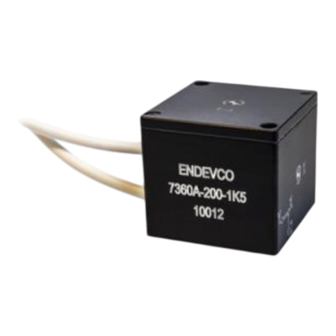
2.0 Product Description The ENDEVCO Model 7360A is a six degrees of freedom (6-DoF) sensor that features three DC accelerometers and three angular rate sensors packaged in a compact enclosure. This 6-DoF sensor is designed specifically for vehicle development testing and other systems requiring accurate measurement of accelerations and angular velocity in harsh shock and vibration environments. -
Page 5: Mounting
Connection Voltage +OUT with respect to GND +2.3V ~ +2.6V -OUT with respect to GND +2.3V ~ +2.6V +OUT with respect to –OUT -100mV ~ +100mV TABLE 1. Output Voltage test for three angular rate sensors check-out If this initial check does not give a proper reading on any of the accelerometers or angular rate sensors, which indicates a possible malfunction, and the reason for the erroneous reading cannot be found, please contact sales@endevco.com troubleshooting or return. -
Page 6: Adhesive Mount
FIGURE 1. Screw Mount of Model 7360A 6-DoF Sensor Note: Suggested distance between the two mounting holes in substrate is 1.414 in (3.59mm). FIGURE 2. Positive sensing directions of the 6-DoF Sensor 5.3. Adhesive Mount Model 7360A 6-DoF sensor can be mounted by adhesives too. Adhesion of epoxies to the hard anodized case is excellent, but thermal mismatch to the mounting surface can degrade the joint and cause an undulating surface. -
Page 7: Cable
5.4. Cable As practical, tie down the cable within 2 to 3 inches (4 to 6 cm) of the unit. Whipping of the cable during rotation, vibration and shock will strain the cable unnecessarily at the unit. The cable has 12x #32 AWG wires. The cable diameter is .118’’... -
Page 8: Signal Leads
A low noise power supply is recommended and care should be taken to minimize pickup on the cabling to the sensor. The maximum current drain over the entire operating range of 7360A and 7360AM1 is 8 mA for each accelerometer axis, and 6 mA for each angular rate axis.
Need help?
Do you have a question about the Endevco 7360A and is the answer not in the manual?
Questions and answers