Table of Contents
Advertisement
Quick Links
Advertisement
Table of Contents
Troubleshooting

Related Manuals for Bardiani Valvole Giotto TOP Teach


Summary of Contents for Bardiani Valvole Giotto TOP Teach
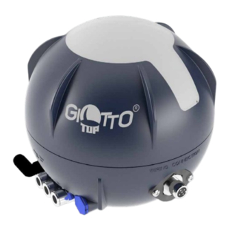
- Page 1 GIOTTO TOP ® TEACH Bardiani Valvole S.p.A. via G. di Vittorio, 50/52 - 43045 Fornovo di Taro (PR) - Italy tel. +39 0525 400044 - fax +39 0525 3408 bardiani@bardiani.com - www.bardiani.com (Translation of the original instructions) EN-IST-GIOT360TEACH-0824...
-
Page 2: Manual Revision
MANUAL REVISION DATE EN-IST-GIOT360TEACH-0824... - Page 3 8.1 Manual override of the solenoid valves in the control head Troubleshooting and error messages Cleaning 10 Disposal 11 Maintenance 11.1 Giotto Top Teach Control unit 11.2 Disassembly / Assembly of the Giotto Top Teach 12 Valve complete with control unit 13 Warranty 14 Recommendations EN-IST-GIOT360TEACH-0824...
- Page 4 INTRODUCTION This “Instruction, Use and Maintenance Manual” has been drawn up expressly for expert technical personnel. Consequently any information which can easily be deducted from reading the text and/or examining the illustrations and/or drawings provided herein shall not be the object of further explanation.
-
Page 5: Safety, Warning And Mandatory Signs
Safety, Warning and Mandatory Signs Safety, Warning and Mandatory Signs SIGNALS Pictogram Description Notes This tells the person in question that the operation WARNING described involves (when not performed in accordance General with the relative safety regulations) the risk of personal injury. -
Page 6: Operator Training
Safety, Warning and Mandatory Signs Operator training All persons who have to work on the valve must be qualified to carry out the relative maintenance tasks. They must be informed as to the possible hazards involved and must observe all the safety instructions set out in this manual. -
Page 7: General Safety Warnings
The control unit must not be used: • for processes other than those intended General safety warnings BARDIANI VALVOLE S.p.A. declines all liability for installation, operation and maintenance contrary to the provisions of these instructions! General notes • Always read the technical data carefully beore machine installation,operation and maintenance. - Page 8 Intended purpose and safety WARNING The machine may not he used inside premises where there is a potentially explosive atmosphere or risk of fire unless otherwise stated by the manufacturer (in the case of valves certified in accordance with Directive 2014/34/EU please refer to the ATEX Manual). WARNING North America –...
-
Page 9: Mechanical Data
Mixproof process valves with air supply for opening and lower (LL) and upper lift (UL) 3 Solenoid valves NC*) NC = normally closed **) NO = normally open In the event of any doubt, please contact Bardiani Valvole SpA. EN-IST-GIOT360TEACH-0824... -
Page 10: Technical Data
Technical data 3.5 Electrical data, IO-Link ELECTRICAL DATA, IO-LINK Power supply of control unit 18 to 30 V DC in accordance with IO-Link specification (protection class 3 in accordance with DIN EN 61140 (VDE 0140-1)) Electrical connections – control unit “IO-Link” Port Class A: M12 plug (4-pin) (POWER 1/POWER 2) Port Class B: M12 plug (5-pin) - Page 11 Technical data 3.6 IO-Link specification IO-LINK SPECIFICATION IO-Link specification V1.1.2 SIO mode Vendor ID 0x0743 (= 1859) Bardiani Valvole Spa Device ID Port Class A: 0xBADA01 (12245505) Port Class B: 0xBADB01 (12245761) IODD file (separately for Port Class A or B) Download from https://ioddfinder.io-link.com...
- Page 12 Technical data 3.7 Electrical data – AS-i ELECTRICAL DATA – AS-INTERFACE Power supply of control unit 29.5 ... 31.6 V DC according to specifications Electrical connections M12 plug (5-pin) See also section 3.12 Details on electrical connections (IO-Link, AS-i, 24 V DC) Current consumption*) Maximum:...
- Page 13 Technical data 3.8 AS-i specification/Bit assignments AS-I SPECIFICATION AS-Interface profile S-7.A.E AS-Interface specification V 3.0 I/O Configuration 7 hex (4 inputs, 4 outputs) ID-Code A hex Extended ID code 1 7 hex Extended ID code 2 E hex AS-i address (factory setting) AS-i profile S-7.A.E (Note: configuration error if an AS-i control head with S-7.A.F is...
- Page 14 Technical data 3.9 Electrical data – 24 V DC ELECTRICAL DATA – 24 V DC Power supply of control unit 18 to 28 V DC (Residual ripple: 10%) Electrical connections Cable gland with M12 plug in accordance with IEC 61076-2-101, 12-pin threaded connection for cable gland PG11 or M20x1.5 See also section 3.12 Details on electrical connections (IO-Link, AS-i, 24 V DC)
- Page 15 *) The feedback fields S1 to S4 can be set using the Bürkert Communicator (büS stick and installer rights for S4 required). The setting for the feedback fields S1 to S3 is also possible via IO-Link. If you have any questions, please contact Bardiani Valvole S.p.A. EN-IST-GIOT360TEACH-0824...
- Page 16 Technical data 3.12 Details on electrical connections (IO-Link, AS-i, 24 V DC) IO-Link Port Class A (electronic module and plug) Solenoid valve Service interface connections with status LED for valves MS, LL, UL Connections power 1, Terminal strip for IO-Link external sensor Pin 1: L+ 24 V DC...
- Page 17 Technical data AS-Interface electronic module and plug Solenoid valve Service interface connections with status LED for valves MS, LL, UL Terminal strips for electrical connection Terminal strip for external sensor Teach keys T1, T2, T3 2 LED status displays Pin 1: ASI + for “Fault”...
- Page 18 Technical data 24 V DC electronic module and terminal strip assignment Terminal strip for ext. Sensor: 24 V - Power supply Solenoid valve 24 V for external sensor Service Service interface connections S4 IN - External input sensor with status LED for - GND ext.
-
Page 19: Double Acting
Technical data 24 V DC electronic module and terminal strip assignment Pin assignment of the M12 connector (according to IEC 61076-2-101) M12 plug, 12-pin: Pin1: 24 V Power supply 24 V DC Pin 2: GND (0 V) Pin 3: S1 (out) Outlet position S1 Pin 4: S2 (out) -
Page 20: Checking / Unpacking / Lifting
Checking / Unpacking / Lifting Checking / Unpacking / Lifting 1. CHECK: - Make sure the control unit shows no signs of damage caused during transport and that it corresponds with the order; 2. PACKING DISPOSAL: The control unit packaging is made up of cardboard, wood and plastic. The control unit is primarily made from plastic materials. - Page 21 Installation of the Giotto Top Installation of the Giotto Top 2xM6x25 Max torque 4 Nm Max torque 2 Nm 114a 114b 114c 114d WARNING Always make sure that all wires are correctly connected and that all parts are installed and securely fastened in the Giotto Top "Teach"...
- Page 22 Checking / Unpacking / Lifting External inductive sensor installation Ø 12,5 MM (M12x1,5) PAG. #51 For proper installation of the extenal inductive sensor, please refer to the installation use and maintenance manual of the valve where the sensor is being installed EN-IST-GIOT360TEACH-0824...
-
Page 23: Giotto Top Pneumatic Connections
Giotto Top pneumatic connections Giotto Top pneumatic connections Air connections to Air vent Compressed Air Inlet. Use hose with an pneumatic actuator external diameter of 6 Use only hose with an external diameter of 6 mm mm. A 1/4" air fitting can be supplied upon request. - Page 24 Giotto Top pneumatic connections Single acting actuator Double acting actuator R e s t R e s t position position EN-IST-GIOT360TEACH-0824...
- Page 25 Giotto Top pneumatic connections Single acting actuator with Twin Double acting actuator with Stop actuator Twin Stop actuator Double seat mixproof actuator EN-IST-GIOT360TEACH-0824...
- Page 26 Giotto Top pneumatic connections Double seal mixproof actuator EN-IST-GIOT360TEACH-0824...
- Page 27 Giotto Top pneumatic connections 6.1 Manual override of the solenoid valves in the control unit If compressed air is present, the process valve can be switched pneumatically using the up to three solenoid valves located in the control head. Each has a manual override that can be used to open or close the solenoid valve (after removing the cap) to control the process valve.
- Page 28 7 Position detection/visual feedback/teach functions 7 Position detection/visual feedback/teach functions Technical data on position detection (targets, external sensor) can be found in section 3.11 Position detection data. 7.1 Position detection for single cam Position detection for single cam valves – with target 1 (and external sensor): The analogue position sensor in the control unit works with a special magnetic target (target 1, for threaded connection M12 or M16).
- Page 29 7 Position detection/visual feedback/teach functions 7.2 Visual feedback (top LED) The following visual feedback signals are given via the top LED according to the position signal combinations S1 to S3 (S4) for the process valve states: FEEDBACK SIGNALS FOR TOP LED DISPLAY (STANDARD) Top LED Colour*) Process valve Process valve “open”...
- Page 30 7 Position detection/visual feedback/teach functions NAMUR display for device status and warnings/errors: In addition to the teach positions, the device status – based on NAMUR – can also be displayed: 0.5 s OFF + 0.5 s device status as double flashing in status colour + 0.5 s OFF. Position and device status (according to NAMUR) can be displayed alternately (continuously alternating) via the top LED, the basic pattern is: 2 s position indicator and 1.5 s device status LED etc.
- Page 31 7 Position detection/visual feedback/teach functions 7.3 Manual teach functions (MTF) MTF – Overview/visual feedback top LED: Each individual position (S1 to S4) can be taught separately by hand. To do this, the process valve or the valve disc must be moved to the desired position (e.g. by manually overriding the solenoid valves –...
- Page 32 7 Position detection/visual feedback/teach functions MTF FOR CONVENTIONAL MIXPROOF VALVES WITHOUT EXTERNAL SENSOR MTF for position Teach key Duration of operation The procedure corresponds to ATF3 (see detailed description ATF3). (An external sensor is not used here.) min. 2.5 s to max. 5 s (process valve: “closed” position) min.
- Page 33 7 Position detection/visual feedback/teach functions 7.4 Automatic teach functions (ATF) ATF – Overview/visual feedback top LED: The teach procedure for the valve positions S1 to S3 can be simplified by the automatic teach function ATF1 to ATF4. The ATF to be applied must be selected in accordance with the process valve type and intended purpose.
- Page 34 7 Position detection/visual feedback/teach functions Detailed description of ATF1: ATF1 is used for the automatic teaching of single-seat valves (NC). Line Activation Effect on the process valve Internal programme Error (5 s to 10 s) Process valve (PV) in teach position S1 (move into) (S1 –...
- Page 35 7 Position detection/visual feedback/teach functions Detailed description of ATF2: ATF2 is used for the automatic teaching of single-seat valves (NO). Line Activation Effect on the process valve Internal programme Error (5 s .. 10 s) Process valve (PV) in teach position S2 (move into) (S2 –...
- Page 36 7 Position detection/visual feedback/teach functions Detailed description of ATF3: ATF3 is used for the automatic teaching of Mixproof classic process valves – with or without external sensors. Line Activation Effect on the process valve Internal programme Error (5 s to 10 s) If an external sensor is used to detect S4, it should first be set to “Upper Lift Position”...
- Page 37 7 Position detection/visual feedback/teach functions Line Activation Effect on the process valve Internal programme Error (5 s to 10 s) If an external sensor is used to detect S4, it shall first be set to “Closed position” before the ATF4 is started. Process valve (PV) in Teach position S1 (move into), i.e.
- Page 38 7 Position detection/visual feedback/teach functions Information on single cam valves. Control unit for single cam process valves have the same behaviour when first installed on site. Once the AS-i or IO-Link communication has been properly installed and set up and cyclical PLC communication to the control unit has been established, the control unit will display the warning “Teach function required”...
-
Page 39: Reset Functions
7 Position detection/visual feedback/teach functions 7.5 Reset functions There are various reset functions that can be started by pressing the teach keys T1 and T2 simultaneously but for different lengths of time – see the following illustration: Reset functions (selection of maintenance, teach, factory reset): min. - Page 40 7 Position detection/visual feedback/teach functions TEACH RESET (T1+T2 FOR 10 TO 20 SECONDS) Top LED display Meaning of visual feedback 2 s (no) position display + 1.5 s “NAMUR” (yellow) = teach |2 s LED off | 1,5 s | 1,5 s reset successful, i.e.: “no position taught”/teach function |2 s LED off (No pos.)
- Page 41 7 Position detection/visual feedback/teach functions The following applies to IO-Link devices: Solenoid valve safety position in event of faulty and/or no cyclical IO-Link communication: all solenoid valves “Off” Service display option (IO-Link only): Service indication display option: “On” (see separate IODD description) External maintenance signalling: disabled (external trigger maintenance function) Local control lock (0x2C10): disabled Factory reset does not reset the following values:...
-
Page 42: Troubleshooting
8 Error messages via top LED 8 Error messages via top LED Signal priorities If several error messages overlap, the highest-ranking message is displayed first (red, orange, yellow, blue). MAINTENANCE DISPLAYS (BLUE) DESCRIPTION POSSIBLE CAUSE TROUBLESHOOTING Switching cycle counter Set limit value has been exceeded. - Check wear parts in pneumatic solenoid valve MS limit value is actuators and armatures... - Page 43 8 Error messages via top LED ERROR MESSAGES (RED) DESCRIPTION POSSIBLE CAUSE TROUBLESHOOTING Position sensor error Faulty position sensor signal caused - Check position sensor target for by lack of target or target outside correct installation and magnet measurement range alignment Teach function error Last teach function failed since last...
-
Page 44: Troubleshooting And Error Messages
8 Error messages via top LED Troubleshooting and error messages FAULT CAUSE REMEDY Air leak at the solenoid valve holder Check the seals for leaks and No seals or loose fitting tighten the screws Air leak at the safety valve Electronic module or Replace electronic module/check electrical connection defective... - Page 45 Cleaning Cleaning Always make sure that the electrical and pneumatic connections are disconnected when carrying out operations on the control unit. 1. PRECAUTIONS The system in which the control unit is installed must be cleaned by expert personnel in observance of the following: - Use only non-abrasive and non-aggressive detergents compatible with the materials which make up the control unit.
- Page 46 Disposal 10 Disposal At the end of its service life, the device must be recycled in accordance with the legislation in force in the country of valve use. Any hazardous residues must be taken into consideration and adequately handled. The control unit is made up of: elastomers (gaskets), plastic (control unit) and electrical components (terminal board, solenoid valves, sensors).
-
Page 47: Maintenance
2. REPLACEMENT OF WEARING PARTS If it is necessary to replace any part of the control unit, it is essential to order an original spare part from Bardiani Valvole S.p.A., as the use of a third-party product may jeopardise correct operation and endanger personnel. - Page 48 Maintenance 11.1 Giotto Top Teach Control unit DESCRIPTION Base Sealing ring Sealing ring Double guide Vent plug Air coupling Air coupling Terminal block with support Screw Bardiani case Sensor Micro-size inductive sensors holder slide 114a Sleeve for cable gland 114b...
- Page 49 Maintenance 192b 192b 192d 192d 192e 192c 192e 192c 114a 114c 114a 114c 114d 114d 114b 114b EN-IST-GIOT360TEACH-0824...
- Page 50 Maintenance 11.2 Assembly instruction of the Giotto Top teach 114a 114c 114d 114b EN-IST-GIOT360TEACH-0824...
- Page 51 Maintenance TYPE B 192b 192e Solenoid valve sequence EN-IST-GIOT360TEACH-0824...
- Page 52 Maintenance Max torque 2 Nm EN-IST-GIOT360TEACH-0824...
- Page 53 Maintenance Max torque 4 Nm EN-IST-GIOT360TEACH-0824...
-
Page 54: Ec Declaration Of Conformity Of The Machinery
- A3-P-PRG-GB EC DECLARATION OF CONFORMITY OF THE MACHINERY (EC) 2006/42, Annex. II, p. 1 A BARDIANI VALVOLE S.p.A. Via G. di Vittorio 50/52 – 43045 Fornovo di Taro (Pr) – Italy Declares under its own responsibility that the machine:... -
Page 55: Exclusions From The Warranty
Notwithstanding and without prejudice to the rights of the Buyer, which may be acknowledged by applicable law, this warranty it to be intended as limited, at the discretion of Bardiani Valvole S.p.A., to the repair and/or replacement of the Product and/or part of the Product and/or its components which is/ are found to be defective due to design and/or manufacturing and/or material faults. - Page 56 “Instruction, Use and Maintenance Manual” which constitutes an integral part of the products themselves. The content and validity of the warranty covering the Products of Bardiani Valvole S.p.A are dealt with in the relevant section in the “Instruction, Use and Maintenance Manual” which constitutes an integral part of the Products themselves.
- Page 57 Recommendations NOTES EN-IST-GIOT360TEACH-0824...
- Page 58 Recommendations NOTES EN-IST-GIOT360TEACH-0824...
- Page 59 Bardiani Valvole S.p.A. via G. di Vittorio, 50/52 - 43045 Fornovo di Taro (PR) - Italy tel. +39 0525 400044 - fax +39 0525 3408 bardiani@bardiani.com - www.bardiani.com...
Need help?
Do you have a question about the Giotto TOP Teach and is the answer not in the manual?
Questions and answers