Table of Contents
Advertisement
Quick Links
Instruction, Use and Maintenance Manual
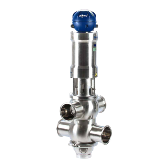
MIXPROOF VALVE
B915PMO
Bardiani Valvole S.p.A.
via G. di Vittorio, 50/52 - 43045 Fornovo di Taro (PR) - Italy
tel. +39 0525 400044 - fax +39 0525 3408
bardiani@bardiani.com - www.bardiani.com
(Translation of the Original Instructions in the italian Language)
EN-IST-B915PMO-1121
Advertisement
Table of Contents

Related Manuals for Bardiani Valvole MIXPROOF B915PMO


Summary of Contents for Bardiani Valvole MIXPROOF B915PMO
- Page 1 Instruction, Use and Maintenance Manual MIXPROOF VALVE B915PMO Bardiani Valvole S.p.A. via G. di Vittorio, 50/52 - 43045 Fornovo di Taro (PR) - Italy tel. +39 0525 400044 - fax +39 0525 3408 bardiani@bardiani.com - www.bardiani.com (Translation of the Original Instructions in the italian Language)
- Page 2 MANUAL REVISION DATE EN-IST-B915PMO-1121...
- Page 3 INDEX Safety, Warning and Mandatory Signs Operator training Safety General safety warnings Electrical connections Technical data Checking / Unpacking / Lifting Installation Operation Troubleshooting Cleaning Disposal 10 Maintenance 10.1 General maintenance 10.2 Scheduled maintenance 10.3 Tools useful for Disassembly/Reassembly 10.4 Mixproof valve B915PMO 10.5 Disassembly of the B915PMO...
- Page 4 INTRODUCTION This “Instruction, Use and Maintenance Manual” has been drawn up expressly for expert technical personnel. Consequently any information which can easily be deducted from reading the text and/or examining the illustrations and/or drawings provided herein shall not be the object of further explanation.
-
Page 5: Safety, Warning And Mandatory Signs
Safety, Warning and Mandatory Signs 1 Safety, Warning and Mandatory Signs WARNING SIGNS Pictogram Description Notes This tells the person in question that the operation CAUTION described involves (when not performed in accordance General with the relative safety regulations) the risk of personal injury. -
Page 6: Skilled Personnel
Safety, Warning and Mandatory Signs MANDATORY SIGNS (FOR THE OPERATOR IN CHARGE OF MECHANICAL MAINTENANCE) Pictogram Description Notes Special instructions must be followed to avoid injury to OBLIGATION persons. General Protective gloves must be available for handling PROTECTIVE GLOVES objects which could cause hand injuries or when there is the possibility of coming into contact with harmful substances.. -
Page 7: Electrical Connection
Safety, Warning and Mandatory Signs OPERATING SIGNS Pictogram Description Notes Use of a press PRESS Use of a press Gradual release of the pressure force PRESS (release) Electrical connection to the control unit (consult the relative ELECTRICAL instruction manual). CONNECTION Electrical disconnection from the control unit (consult the ELECTRICAL relative instruction manual). -
Page 8: Operator Training
Safety, Warning and Mandatory Signs 1.1 Operator training All persons who have to work on the valve must be quali昀椀ed to carry out the relative maintenance tasks. They must be informed as to the possible hazards involved and must observe all the safety instructions set out in this manual. Allow expert personnel only to work on the electrical components. -
Page 9: General Safety Warnings
昀椀re unless otherwise stated by the manufacturer (in the case of valves certi昀椀ed in accordance with Directive 2014/34/EU please refer to the ATEX Manual). BARDIANI VALVOLE S.p.A. declines all liability for installation, use or maintenance which fails to comply with the indications provided in this manual! 2.2 Electrical connections... -
Page 10: Technical Data
- valves with DN125 or bigger with group 2 昀氀uids. The end user must carry out noise assessment testing once the valve has been installed in the plant. In the event of any doubt, please contact Bardiani Valvole S.p.A. EN-IST-B915PMO-1121... -
Page 11: Checking / Unpacking / Lifting
Checking / Unpacking / Lifting 4 Checking / Unpacking / Lifting 1. CHECK: - Check the valve show no signs of damage caused during transport and that it corresponds with the order; - Check the inside of the valve. 2. UNPACKING: The valve packaging is made up of cardboard, wood and plastic. - Page 12 Checking / Unpacking / Lifting 3. VALVE LIFTING: Take care as to the type of valve you are handling. Based on the size there are two different lifting procedures. CAUTION! Before lifting the valve, make sure there are no disassembled or separate valve parts which could fall off causing injury to persons and damage to the valve.
-
Page 13: Installation
Installation 5 Installation 1. ELECTRICAL AND PNEUMATIC ENERGY SUPPLY - Use expert personnel for installation/uninstallation operations; - Check that the air pressure and quality are correct (see "Technical Data"); - Check the power supply to the control unit is correct (consult the relative instruction manual). - Page 14 Technical data 4. VALVE CONNECTIONS/CONNECTORS: If the valve is 昀椀tted with connectors, you may proceed with installation. Correctly insert the gaskets and tighten the connectors. 5. WALDING THE VALVE BODY ONTO PIPING: 1. Blow air into the central union 2. Remove the body from the rest of the valve before proceeding with welding operations.
- Page 15 Technical data 6. MINIMUM MAINTENANCE CLEARANCES: Make sure there is enough room around the valve for it to be disassembled (with the control unit installed). B915PM0 A (mm) B (mm) 15÷40 7. ORIENTATION OF THE DOUBLE BODY: Pay attention to body orientation. In the double body, the UP arrows indicates the valve actuator position.
- Page 16 Technical data 9.PREPARING THE VALVE FOR INSTALLATION: To move the valve, 昀椀rst screw in the eye bolts. Once valve installation has been completed, remove the eyebolts and put the screws back in EN-IST-B915PMO-1121...
-
Page 17: Operation
Operation 6 Operation 2. VALVE INSPECTION BEFORE OPERATION: - Supply air to the actuator; - Power the valve (via the control unit); - Open and close the valve several times; - Check that the valve works correctly and accurately. 1 = Opening 2 = Top lift 3 = Bottom lift CAUTION! -
Page 18: Troubleshooting
Troubleshooting 7 Troubleshooting PROBLEM POSSIBLE CAUSE POSSIBLE SOLUTION External leak Worn gasket Replace the seal Leaks inside the closed valve caused by normal wear Excessive pressure Replace with a gasket of a External leak different type of elastomer Excessive temperature Aggressive 昀氀uids Premature leaks... - Page 19 Cleaning 8 Cleaning 1. VALVE CLEANING WITH DETERGENTS: The system in which the valve is installed must be cleaned by expert personnel in observance of the following: - Abide by the indicated detergent concentration values; - Observe the instructions provided by the detergent manufacturer. - Always wear protective safety glasses and gloves.
- Page 20 Disposal 9 Disposal At the end of its service life, the device must be recycled in accordance with the legislation in force in the country of valve use. Any hazardous residues must be taken into consideration and adequately handled. The valve is made of AISI 316L and AISI 304 stainless steel, elastomers (gaskets), plastic (control unit) and electrical components (terminal boards, solenoid valves, sensors).
- Page 21 Maintenance 10 Maintenance 10.1 General maintenance 1. MAINTENANCE PRECAUTIONS Maintenance operations must be carried out by expert technicians only. CAUTION! Maintenance operations must be carried out with the line stopped and all utilities (electricity, compressed air) disconnected. CAUTION! Always discharge the 昀氀uid pressure in the valve and piping before disassembling the valve.
-
Page 22: Scheduled Maintenance
Maintenance 2. CLEANING AWAY DEPOSITS: - Thoroughly wash and clean all the valve parts before disassembly; - Pay attention to any possible detergent or other aggressive 昀氀uid deposits (see "Cleaning"); - Always use protective safety glasses and gloves when required. CAUTION! Hand crushing hazard. -
Page 23: Tools Useful For Disassembly/Reassembly
Maintenance 10.3 Tools useful for Disassembly/Reassembly TOOLS Soft EN-IST-B915PMO-1121... - Page 24 Maintenance 10.4 Mixproof valve B915PMO DESCRIPTION DESCRIPTION Valve body Air coupling Upper shutter Air coupling Seal ring Threaded locking nuts Cylinder Seal ring Shaft Seal ring Seal ring Seal ring Central piston Seal ring Seal ring Secondary spring Seal ring Seal ring Guide bushing Seal ring...
- Page 25 Maintenance EN-IST-B915PMO-1121...
- Page 26 Maintenance [A S B915PMO] 10.5 Disassembly of the B915PMO EN-IST-B915PMO-1121...
- Page 27 Maintenance EN-IST-B915PMO-1121...
- Page 28 Maintenance EN-IST-B915PMO-1121...
-
Page 29: Handle With Care
Maintenance Never touch the moving parts if the actuator is supplied with complessed air HANDLE WITH CARE EN-IST-B915PMO-1121... - Page 30 Maintenance EN-IST-B915PMO-1121...
- Page 31 Maintenance EN-IST-B915PMO-1121...
- Page 32 Maintenance EN-IST-B915PMO-1121...
- Page 33 Maintenance EN-IST-B915PMO-1121...
- Page 34 Maintenance EN-IST-B915PMO-1121...
- Page 35 Maintenance EN-IST-B915PMO-1121...
- Page 36 Maintenance EN-IST-B915PMO-1121...
- Page 37 Maintenance EN-IST-B915PMO-1121...
- Page 38 Maintenance EN-IST-B915PMO-1121...
- Page 39 Maintenance 10.6 Assembly of the B915PMO EN-IST-B915PMO-1121...
- Page 40 Maintenance EN-IST-B915PMO-1121...
- Page 41 Maintenance EN-IST-B915PMO-1121...
- Page 42 Maintenance EN-IST-B915PMO-1121...
- Page 43 Maintenance EN-IST-B915PMO-1121...
- Page 44 Maintenance EN-IST-B915PMO-1121...
- Page 45 Maintenance EN-IST-B915PMO-1121...
- Page 46 Maintenance EN-IST-B915PMO-1121...
- Page 47 Maintenance EN-IST-B915PMO-1121...
- Page 48 Maintenance HANDLE WITH CARE EN-IST-B915PMO-1121...
- Page 49 Maintenance Never touch the moving parts if the actuator is supplied with complessed air EN-IST-B915PMO-1121...
- Page 50 Maintenance EN-IST-B915PMO-1121...
- Page 51 Maintenance Never touch the moving parts if the actuator is supplied with complessed air EN-IST-B915PMO-1121...
- Page 52 Maintenance EN-IST-B915PMO-1121...
- Page 53 Maintenance 10.7 Lower seatlift sensor adjustment To comply with PMO Section 7, Item 15p(B) compliant including Part 6 exception for (seat-lifting), carry out the following steps to position and adjust the proximity sensor to detect a 1.59 mm seat lift movement. Lower seat lift downward stroke: 7.5 mm. Carry out the following steps : Open the control unit and remove the cam from the shaft.
- Page 54 Maintenance When the valve is in the close position set the proximity switch to have the its lower quarter active sensing zone in correspondence with the upper part of the cam. Activate the lower lift with regulated air at 6 bar in the upper air connection in the actuator.
- Page 55 Maintenance Activate the lower seat lift with regulated air at 6 bar in the upper air connection in the actuator. Seat lift lower shutter will open. The LED on the Proximity switch must now be light ON. EN-IST-B915PMO-1121...
- Page 56 Maintenance 10.8 Upper seatlift external adjustment To comply with PMO Section 7, Item 15p(B) compliant including Part 6 exception for (seat-lifting), carry out the following steps to position and adjust the proximity sensor to detect a 1.59 mm seat lift movement. Upper seat lift upward stroke: 2mm. Carry out the following steps : Valve must be in its closed position, Assemble the proximity switch, two nuts...
- Page 57 Maintenance Activate the upper seat lift with regulated air at 6 bar in the lower air connection in the actuator. Adjust and regulate the proximity switch position until the lower middle section of the sensitive area is in correspondence with the upper edge of the upper shutter.
- Page 58 Maintenance Seat lift upper shutter will open, with a stroke of 2mm The LED on the Proximity switch must now be lit ON, with NO feedback signal to the control system. EN-IST-B915PMO-1121...
- Page 59 Maintenance 10.9 External sensor electrical connections EN-IST-B915PMO-1121...
-
Page 60: Ec Declaration Of Conformity Of The Machinery
- A3-P-PRG-GB EC DECLARATION OF CONFORMITY OF THE MACHINERY (EC) 2006/42, Annex. II, p. 1 A BARDIANI VALVOLE S.p.A. Via G. di Vittorio 50/52 – 43045 Fornovo di Taro (Pr) – Italy Declares under its own responsibility that the machine:... - Page 61 2D diagram B915PMO 12 2D diagram B915PMO "[A S B915PMO]" EN-IST-B915PMO-1121...
-
Page 62: Warranty
Notwithstanding and without prejudice to the rights of the Buyer, which may be acknowledged by applicable law, this warranty it to be intended as limited, at the discretion of Bardiani Valvole S.p.A., to the repair and/or replacement of the Product and/or part of the Product and/or its components which is/ are found to be defective due to design and/or manufacturing and/or material faults. - Page 63 Manufacturer Bardiani Valvole S.p.A. holds to be reliable nevertheless the above is not deemed to be assumed as fully exhaustive inasmuch as not every possible use has been envisaged.
- Page 64 Recommendations NOTES EN-IST-B915PMO-1121...
- Page 65 Bardiani Valvole S.p.A. via G. di Vittorio, 50/52 - 43045 Fornovo di Taro (PR) - Italy tel. +39 0525 400044 - fax +39 0525 3408 bardiani@bardiani.com - www.bardiani.com...
Need help?
Do you have a question about the MIXPROOF B915PMO and is the answer not in the manual?
Questions and answers