Compaq Presario,Presario 900 Maintenance And Service Manual
Hp compaq presario,presario 900: user guide
Hide thumbs
Also See for Compaq Presario,Presario 900:
- Supplementary manual (158 pages) ,
- User manual (138 pages) ,
- Reference manual (133 pages)
Table of Contents
Advertisement
Quick Links
b
Maintenance and Service Guide
Compaq Evo Notebook N1005 Series
Compaq Presario 900 Series Mobile PC
Document Part Number: 272638-002
November 2002
This guide is a troubleshooting reference used for maintaining
and servicing the notebook. It provides comprehensive
information on identifying computer features, components, and
spare parts, troubleshooting computer problems, and performing
computer disassembly procedures.
Advertisement
Chapters
Table of Contents
Troubleshooting

Related Manuals for Compaq Compaq Presario,Presario 900


Summary of Contents for Compaq Compaq Presario,Presario 900
-
Page 1: Maintenance And Service Guide
Maintenance and Service Guide Compaq Evo Notebook N1005 Series Compaq Presario 900 Series Mobile PC Document Part Number: 272638-002 November 2002 This guide is a troubleshooting reference used for maintaining and servicing the notebook. It provides comprehensive information on identifying computer features, components, and spare parts, troubleshooting computer problems, and performing computer disassembly procedures. - Page 2 © 2002 Compaq Information Technologies Group, L.P. Compaq, the Compaq logo, Evo, and Presario are trademarks of Compaq Information Technologies Group, L.P. in the U.S. and/or other countries. Microsoft and Windows are trademarks of Microsoft Corporation in the U.S. and/or other countries. All other product names mentioned herein may be trademarks of their respective companies.
-
Page 3: Table Of Contents
Contents 1 Product Description 1.1 Models ........1–2 1.2 Features . - Page 4 Contents 3 Illustrated Parts Catalog 3.1 Serial Number Location ..... . . 3–1 3.2 Computer System Major Components ... . 3–2 3.3 Miscellaneous Plastics/Hardware Kit .
- Page 5 Contents 5.9 LED Cover ....... . 5–19 5.10 Keyboard ....... . 5–21 5.11 Heat Spreader .
-
Page 6: Product Description
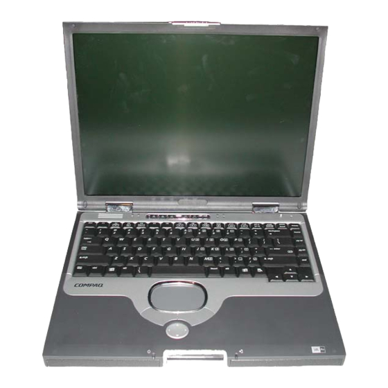
Product Description The Compaq Evo Notebook N1015 Series, Evo Notebook N1005 Series, and Presario 900 Series Mobile PCs offer advanced modularity, AMD Athlon and Duron processors, industry-leading Accelerated Graphics Port (AGP) implementation, and extensive multimedia support. Figure 1-1. Compaq Evo Notebook N1015 Series, Evo Notebook N1005 Series, and Presario 900 Series Mobile PCs Maintenance and Service Guide... -
Page 7: Models
Product Description 1.1 Models Computer models are shown in Tables 1-1 through 1-4. Table 1-1 Compaq Evo Notebook N1015, Notebook N1005, and Presario 900 Model Naming Conventions P900 XXXXXX-XXX Description Options Brand/Series E = Evo 1015 = 1015 Series designator P = Presario 1005 = 1005 Series 900 = 900 Series... - Page 8 Product Description Table 1-2 Compaq Evo Notebook N1015 Series Models The following Evo Notebook N1015 Series model uses config. code KSXZ and features: ■ TouchPad ■ 8-cell, 4.0-Ah lithium ion (Li ion) battery pack ■ 2-year warranty ■ diskette drive N1015 Germany 470046-613...
- Page 9 Product Description Table 1-2 Compaq Evo Notebook N1015 Series Models (Continued) N1015 Asia Pacific 470047-372 N1015 Latin America 470050-296 United States - 0.2 N1015 French Canada 470045-406 United States 470045-407 N1015 United States 470046-093 includes Microsoft Office Pro software N1015 French Canada 470046-577 United States...
- Page 10 Product Description Table 1-2 Compaq Evo Notebook N1015 Series Models (Continued) N1015 Belgium 470046-581 Norway 470046-591 Czech Republic 470046-582 Portugal 470046-592 Denmark 470046-583 Russia 470046-600 European 470046-584 Saudi Arabia 470046-580 International Slovenia 470046-602 France 470046-585 Spain 470046-603 Greece/Poland 470046-586 Sweden/Finland 470046-605 Hungary 470046-587...
- Page 11 Product Description Table 1-2 Compaq Evo Notebook N1015 Series Models (Continued) N1015 Latin America 470050-688 N1015 French Canada 470046-578 United States 470047-371 United States 470046-573 GEM/NAFTA Table 1-3 Compaq Evo Notebook N1005 Series Models The following Evo Notebook N1005 Series models use config. code KSXZ and features: ■...
- Page 12 Product Description Table 1-3 Compaq Evo Notebook N1005 Series Models (Continued) The following Evo Notebook N1005 Series models use config. code KSBZ and features: ■ TouchPad ■ 8-cell, 4.0-Ah lithium ion (Li ion) battery pack ■ 1-year warranty ■ diskette drive N1005 Belgium 470041-815...
- Page 13 Product Description Table 1-4 Compaq Presario 900 Series Mobile PC Models The following Presario 900 Series Mobile PC models use config. code KSXZ and features: ■ TouchPad ■ 8-cell, 4.0-Ah lithium ion (Li ion) battery pack ■ 2-year warranty ■ diskette drive P920 Belgium...
- Page 14 Product Description Table 1-4 Compaq Presario 900 Series Mobile PC Models (Continued) P910 Belgium 470045-616 Norway 470045-633 Germany 470045-622 P902 Belgium 470037-046 Norway 470037-080 Denmark 470037-068 Portugal 470037-516 Germany 470037-071 Spain 470037-520 Italy 470037-074 Sweden/Finland 470037-081 The Netherlands 470037-077 P908 Belgium 470046-499 Norway...
- Page 15 Product Description Table 1-4 Compaq Presario 900 Series Mobile PC Models (Continued) The following Presario 900 Series Mobile PC model uses config. code KSB2 and features: ■ TouchPad ■ 8-cell, 4.0-Ah lithium ion (Li ion) battery pack ■ 1-year warranty ■...
- Page 16 Product Description Table 1-4 Compaq Presario 900 Series Mobile PC Models (Continued) P920 Denmark - 0.7 The Netherlands 470048-557 European 470045-495 Portugal 470048-427 International Russia 470045-514 France 470045-500 Saudi Arabia 470045-494 Greece/Poland 470045-501 Spain 470048-428 Hungary 470045-507 Sweden/Finland 470050-685 Israel 470045-508 Switzerland 470045-515...
- Page 17 Product Description Table 1-4 Compaq Presario 900 Series Mobile PC Models (Continued) P905 European Russia 470037-140 International 470037-133 Saudi Arabia 470037-127 France 470037-134 Switzerland 470037-345 Germany 470037-138 Turkey 470037-151 Hungary 470040-102 United Kingdom 470037-152 Israel 470037-305 P917 European 470049-153 International P906 European 470039-301...
- Page 18 Product Description Table 1-4 Compaq Presario 900 Series Mobile PC Models (Continued) P906 Korea 470037-514 P905 Australia/New Zealand 470037-311 P904 Taiwan 470045-531 P916 French Canada 470046-482 United States 470046-475 P940 Taiwan 470048-553 P927 India 470050-293 P904 European Russia 470038-106 International 470038-102 Saudi Arabia 470038-101...
- Page 19 Product Description Table 1-4 Compaq Presario 900 Series Mobile PC Models (Continued) P925 People’s Republic of 470048-549 China P905 Brazil 470037-309 Latin America 470037-288 Hong Kong 470037-289 (NAFTA) Latin America 470037-277 Taiwan 470037-315 P900 Canada English 470037-117 French Canada 470037-279 P912 United States 470045-487...
- Page 20 Product Description Table 1-4 Compaq Presario 900 Series Mobile PC Models (Continued) P923 Korea 470050-292 P900 Latin America 470045-490 Latin America 470045-491 NAFTA P902 European 470037-132 Russia 470037-141 International Saudi Arabia 470037-126 France 470037-135 Switzerland 470037-344 Germany 470037-137 Turkey 470037-150 Israel 470037-304 United Kingdom...
- Page 21 Product Description Table 1-4 Compaq Presario 900 Series Mobile PC Models (Continued) P907 European 470047-365 Italy 470048-562 International Saudi Arabia 470047-899 France 470046-487 Spain 470048-423 Greece/Poland 470046-493 Sweden/Finland 470048-561 Hungary 470047-900 Switzerland 470046-490 Israel 470047-901 P905 Hong Kong 47046-481 P902 Australia/New Zealand 470038-110 P903...
-
Page 22: Features
Product Description Table 1-4 Compaq Presario 900 Series Mobile PC Models (Continued) P909 Portugal 470050-684 P900 Asia Pacific 470040-356 Korea 470040-357 Australia/New Zealand 470040-354 Thailand 470040-355 1.2 Features The notebook has the following features: ■ AMD Athlon XP+ 1.67-, 1.60-, 1.53-, 1.47-, 1.40-, 1.30-, or 1.20-GHz processors, or AMD Duron 1.30-GHz processor, varying by notebook model ■... -
Page 23: Clearing A Password
Product Description ■ 40-, 30-, or 20-GB high-capacity hard drive, varying by computer model ■ 1.44-MB diskette drive ■ Support for the following drives through the fixed optical drive: ❏ 24X Max CD-ROM drive ❏ 16X Max CD-RW drive ❏ 8X Max DVD-ROM drive ❏... -
Page 24: Power Management
Product Description 2. Remove the RTC battery (refer to Section 5.7, “Disk Cell RTC Battery”). 3. Wait approximately five minutes. 4. Replace the RTC battery and reassemble the computer. 5. Connect AC power to the computer. Do not reinsert any battery packs at this time. -
Page 25: Computer External Components
Product Description 1.5 Computer External Components The external components on the front and right side of the computer are shown in Figure 1-2 and described in Table 1-4. Figure 1-2. Front and Right Side Components Table 1-4 Front and Right Side Components Item Component Function... - Page 26 Product Description Table 1-4 Front and Right Side Components (Continued) Item Component Function Display release latch Opens the computer. Battery light On: A battery pack is charging. Blinking: A battery pack that is the only available power source has reached a low-battery condition.
- Page 27 Product Description The computer rear panel and left side components are shown in Figure 1-3 and described in Table 1-5. Figure 1-3. Rear Panel and Left Side Components Table 1-5 Rear Panel and Left Side Components Item Component Function Stereo speaker/ Connects stereo speakers, headphones, headphone jack headset, or television audio.
- Page 28 Product Description Table 1-5 Rear Panel and Left Side Components (Continued) Item Component Function Provides airflow to cool internal components. S-Video connector Connects a television, VCR, camcorder, or overhead projector. External monitor Connects an external monitor or overhead connector projector. External Connects an optional full-sized keyboard or keyboard/mouse...
- Page 29 Product Description The computer keyboard components are shown in Figure 1-4 and described in Table 1-6. Figure 1-4. Keyboard Components Table 1-6 Keyboard Components Item Component Function through Perform preset functions. function keys Used with hotkeys to perform preset hotkey functions.
- Page 30 Product Description Table 1-6 Keyboard Components (Continued) Item Component Function Windows logo keys Display the Windows Start menu. Windows application Displays a menu when using a Microsoft application. The menu is the same one that is displayed by pressing the right mouse button.
- Page 31 Product Description The computer top components are shown in Figure 1-5 and described in Table 1-7. Figure 1-5. Top Components Table 1-7 Top Components Item Component Function Power light On: Power is turned on. Blinking: Computer is in Standby. The power light also blinks if a battery pack that is the only available power source reaches a low-battery condition.
- Page 32 Product Description Table 1-7 Top Components (Continued) Item Component Function Power button Turns on the computer. Use the operating system Shut Down command to turn off the computer. Digital audio button Launches Windows Media Player to play MP3 music. Volume control buttons Adjust the volume of the stereo speakers.
- Page 33 Product Description The external components on the bottom of the computer are shown in Figure 1-6 and described in Table 1-8. Figure 1-6. Bottom Components Table 1-8 Bottom Components Item Component Function Hard drive retention screw Secures the hard drive to the computer.
- Page 34 Product Description Table 1-8 Bottom Components (Continued) Item Component Function RJ-11 modem jack Connects the modem cable to an internal modem. A modem cable is included with internal modem models. RJ-45 network jack Connects the network cable. A network cable is not included with the computer.
-
Page 35: Design Overview
Product Description 1.6 Design Overview This section presents a design overview of key parts and features of the computer. Refer to Chapter 3, “Illustrated Parts Catalog,” to identify replacement parts and Chapter 5, “Removal and Replacement Procedures,” for disassembly steps. The system board provides the following device connections: ■... -
Page 36: Troubleshooting
Troubleshooting Å WARNING: Only authorized technicians trained by Compaq should repair this equipment. All troubleshooting and repair procedures are detailed to allow only subassembly/module level repair. Because of the complexity of the individual boards and subassemblies, no one should attempt to make repairs at the component level or make modifications to any printed wiring board. -
Page 37: Using Computer Setup
Troubleshooting ■ Compaq Diagnostics—A system information and diagnostic utility that is used within your Windows operating system. Use this utility whenever possible to: ❏ Display system information. ❏ Test system components. ❏ Troubleshoot a device configuration problem in Windows 2000, Windows XP Professional, or Windows XP Home. -
Page 38: Selecting From The File Menu
Troubleshooting Selecting from the File Menu Table 2-1 File Menu Select To Do This ■ System Information View identification information about the computer, a docking base, and any battery packs in the system. ■ View specification information about the processor, memory and cache size, and system ROM. -
Page 39: Selecting From The Security Menu
Troubleshooting Selecting from the Security Menu Table 2-2 Security Menu Select To Do This Setup Password Enter, change, or delete a setup password. (The setup password is called an administrator password in Compaq Computer Security, a program accessed from the Windows Control Panel.) Power-on Password Enter, change, or delete a power-on password. -
Page 40: Selecting From The Advanced Menu
Troubleshooting Selecting from the Advanced Menu Table 2-3 Advanced Menu Select To Do This Language (or press Change the Computer Setup language. Boot Options Enable/disable: ■ QuickBoot, which starts the computer more quickly by eliminating some startup tests. (If you suspect a memory failure and want to test memory automatically during startup, disable QuickBoot.) ■... - Page 41 Troubleshooting Table 2-3 Advanced Menu (Continued) Select To Do This ■ Device Options Change the parallel port mode from (continued) Enhanced Parallel Port (EPP, the default setting) to standard, bidirectional, EPP or Enhanced Capabilities Port (ECP). ■ Set video-out mode to NTSC (default), PAL, NTSC-J, or PAL-M.* ■...
-
Page 42: Using Compaq Diagnostics
Troubleshooting 2.2 Using Compaq Diagnostics When you access Compaq Diagnostics, a scan of all system components is displayed on the screen before the Compaq Diagnostics window opens. You can display more or less information from anywhere within Compaq Diagnostics by selecting Level on the menu bar. Compaq Diagnostics is designed to test Compaq components. -
Page 43: Obtaining, Saving, Or Printing Diagnostic
Troubleshooting Obtaining, Saving, or Printing Diagnostic Test Information 1. Access Compaq Diagnostics by selecting Start > Settings > Control Panel > Compaq Diagnostics. 2. Select the Test tab. 3. In the scroll box, select the category or device you want to test. - Page 44 Troubleshooting 5. Select a test mode: ❏ Interactive Mode—Provides maximum control over the testing process. You determine whether the test was passed or failed, and you may be prompted to insert or remove devices. ❏ Unattended Mode—Does not display prompts. If errors are found, they are displayed when testing is complete.
-
Page 45: Troubleshooting Flowcharts
Troubleshooting 2.3 Troubleshooting Flowcharts Table 2-4 Troubleshooting Flowcharts Overview Flowchart Description Initial Troubleshooting No Power, Part 1 No Power, Part 2 No Power, Part 3 No Power, Part 4 No Video, Part 1 No Video, Part 2 Nonfunctioning Docking Station No Operating System (OS) Loading 2.10 No OS Loading From Hard Drive, Part 1... -
Page 46: Flowchart 2.2
Troubleshooting Flowchart 2.1 - Initial Troubleshooting Begin troubleshooting. Go to Is there Flowchart 2.2, power? No Power, Part 1. Check Beeps, LED board, LEDs, or error speaker messages? connections. Go to All drives Flowchart 2.17, working? Nonfunctioning Device. Go to Is there video? Flowchart 2.6, Go to... - Page 47 Troubleshooting Flowchart 2.2 - No Power, Part 1 No power (power LED is off). Remove from docking station (if applicable). Go to Power up Power up *Reset Flowchart 2.3, on battery on battery power. No Power, power? power? Part 2. Go to Power up Power up...
-
Page 48: No Power, Part 1
Troubleshooting Flowchart 2.3 - No Power, Part 2 Continued from Flowchart 2.2, No Power, Part 1. Visually check for debris in battery socket and clean if necessary. Power on? Done Check battery by recharging, moving it to another computer, or replacing it. Replace power supply Power on? - Page 49 Troubleshooting Flowchart 2.4 - No Power, Part 3 Continued from Flowchart 2.3, No Power, Part 2. Plug directly into AC outlet. Power LED Done Reseat AC adapter in computer and at power source. Power on? Done External Internal or Replace external Power outlet Try different external AC...
- Page 50 Troubleshooting Flowchart 2.5 - No Power, Part 4 Continued from Flowchart 2.4, No Power, Part 3. Open computer. Reseat loose components and Loose or boards and damaged replace parts? damaged items. Close computer and retest. Replace the following items (if applicable). Power on? Check computer operation after each replacement:...
- Page 51 Troubleshooting Flowchart 2.6 - No Video, Part 1 No video. Docking station *To change from internal to Go to Stand-alone external display, use the hotkey Flowchart 2.7, or docking combination. No Video, Part 2. station? Stand-alone Internal or Adjust Done external Video OK? brightness.
-
Page 52: No Video, Part 1
Troubleshooting Flowchart 2.7 - No Video, Part 2 Continued from Flowchart 2.6, No Video, Part 1. Remove notebook from docking station, if connected. Adjust Check brightness display of external brightness. monitor. Go to “A” in Done Flowchart 2.6, Video OK? Video OK? No Video, Part 1. -
Page 53: Nonfunctioning Docking Station
Troubleshooting Flowchart 2.8 - Nonfunctioning Docking Station (if applicable) Nonfunctioning docking station. Reseat power cord in docking station and power outlet. Check voltage Reinstall setting on notebook into docking station. docking station. Reset monitor cable connector at Docking docking station. station Done operating? -
Page 54: No Os Loading From Hard Drive, Part
Troubleshooting Flowchart 2.9 - No Operating System (OS) Loading No OS loading.* Reseat power *Before beginning troubleshooting, always cord in docking check cable connections, cable ends, and station and drives for bent or damaged pins. power outlet. No OS loading from hard drive, go to Flowchart 2.10, No OS Loading from... - Page 55 Troubleshooting Flowchart 2.10 - No OS Loading from Hard Drive, Part 1 OS not loading from hard drive. Go to Flowchart 2.11, Nonsystem No OS Loading disk message? from Hard Drive, Part 2. Reseat external hard drive. OS loading? Done Boot from Go to Flowchart 2.13,...
- Page 56 Troubleshooting Flowchart 2.11 - No OS Loading from Hard Drive, Part 2 Continued from Flowchart 2.10, No OS Loading Reseat from Hard Drive, hard drive. Part 1. 1. Replace hard CD or drive. diskette in 2. Replace Hard drive drive? Done system board.
- Page 57 Troubleshooting Flowchart 2.12 - No OS Loading from Hard Drive, Part 3 Continued from Flowchart 2.11, No OS Loading from Hard Drive, Part 2. System Install OS files on hard and reboot. drive? Virus on hard Clean virus. Done loading from drive? hard drive? Run SCANDISK...
- Page 58 Troubleshooting Flowchart 2.13 - No OS Loading from Diskette Drive OS not loading Reseat from Done loading? diskette drive. diskette drive. Install bootable Bootable Nonsystem diskette and diskette disk message? reboot computer. in drive? Check diskette Go to Boot for system files. Flowchart 2.17, from another Try different...
- Page 59 Troubleshooting Flowchart 2.14 - No OS Loading from CD- or DVD-ROM Drive No OS Install Bootable Disc loading from bootable disc disc in in drive? CD- or and reboot drive? DVD-ROM Drive. computer. Install Try another bootable disc. bootable disc. Boots from Done CD or DVD?
- Page 60 Troubleshooting Flowchart 2.15 - No Audio, Part 1 Turn up audio No audio. internally or Audio? Done externally. Notebook in Go to Internal docking station Undock Flowchart 2.16, audio? (if applicable)? No Audio, Part 2. Replace the following docking station Go to components one at a time as applicable.
- Page 61 Troubleshooting Flowchart 2.16 - No Audio, Part 2 Continued from Flowchart 2.15, No Audio, Part 1. Audio Reload driver in OS audio drivers. configured? Load drivers Correct and set drivers for configuration application? in OS. Connect to external speaker. Replace audio board and speaker Audio?
- Page 62 Troubleshooting Flowchart 2.17 - Nonfunctioning Device Nonfunctioning device. Reseat device. Unplug the nonfunctioning device from the notebook and inspect cables and plugs for bent or broken pins or other damage. Fix or Any physical Clear replace device detected? CMOS. broken item. Reattach device.
- Page 63 Troubleshooting Flowchart 2.18 - Nonfunctioning Keyboard Keyboard not operating properly. Connect notebook to good external keyboard. Replace External system device board. works? Reseat internal keyboard connector (if applicable). Replace internal keyboard or cable. Done Done Replace system board. 2–28 Maintenance and Service Guide...
- Page 64 Troubleshooting Flowchart 2.19 - Nonfunctioning Pointing Device Pointing device not operating properly. Connect notebook to good external pointing device. Replace External system device board. works? Reseat internal pointing device connector (if applicable). Replace internal pointing device or cable. Done Done Replace system board.
- Page 65 Troubleshooting Flowchart 2.20 - No Network or Modem Connection No network or modem connection. Network or Replace jack modem jack or have jack active? activated. Connect Digital to nondigital line? line. Reload NIC/modem drivers and Done configured reconfigure. in OS? Disconnect all Replace power from...
-
Page 66: Illustrated Parts Catalog
Illustrated Parts Catalog This chapter provides an illustrated parts breakdown and a reference for spare part numbers and option part numbers. 3.1 Serial Number Location When ordering parts or requesting information, provide the computer serial number and model number located on the bottom of the computer (Figure 3-1). -
Page 67: Computer System Major Components
Illustrated Parts Catalog 3.2 Computer System Major Components Figure 3-2. Computer System Major Components 3–2 Maintenance and Service Guide... - Page 68 Illustrated Parts Catalog Table 3-1 Spare Parts: Computer System Major Components Spare Part Item Description Number Displays for use only with Evo Notebook N1015 models 15.0-inch, TFT, XGA 310689-001 14.1-inch, TFT, XGA 311286-001 13.3-inch, TFT, XGA 309645-001 for use only with Evo Notebook N1005 models 15.0-inch, TFT, SXGA+ 291643-001 15.0-inch, TFT, XGA...
- Page 69 Illustrated Parts Catalog Figure 3-2. Computer System Major Components 3–4 Maintenance and Service Guide...
- Page 70 Illustrated Parts Catalog Table 3-1 Spare Parts: Computer System Major Components (Continued) Spare Part Item Description Number Miscellaneous Plastics/Hardware Kit, includes: 285541-001 Left hinge cover Right hinge cover *Display release assembly TouchPad bracket Charger board shield Optical drive rear alignment rail Optical drive front alignment rail PC Card space saver *Connector cover...
- Page 71 Illustrated Parts Catalog Figure 3-2. Computer System Major Components 3–6 Maintenance and Service Guide...
- Page 72 Illustrated Parts Catalog Table 3-1 Spare Parts: Computer System Major Components (Continued) Spare Part Item Description Number Keyboards Arabic 285530-171 Korean 285530-AD1 Belgian 285530-181 Latin American 285530-161 Brazilian 285530-201 Spanish Chinese 285530-AA1 Norwegian 285530-091 Czech 285530-221 Portuguese 285530-131 Danish 285530-081 Russian 285530-251 French...
- Page 73 Illustrated Parts Catalog Figure 3-2. Computer System Major Components 3–8 Maintenance and Service Guide...
- Page 74 Illustrated Parts Catalog Table 3-1 Spare Parts: Computer System Major Components (Continued) Spare Part Item Description Number Palm rests for use only with Evo Notebook N1015 models 311955-001 (does not include pointing stick or diskette drive) for use only with Presario 900 models using 45W 310693-001 processors* (does not include pointing stick or diskette drive)
- Page 75 Illustrated Parts Catalog Figure 3-2. Computer System Major Components 3–10 Maintenance and Service Guide...
- Page 76 Illustrated Parts Catalog Table 3-1 Spare Parts: Computer System Major Components (Continued) Spare Part Item Description Number Heat spreaders for use only with AMD Athlon XP 45W processors* 309646-001 for use only with AMD Athlon XP non-45W 291594-001 processors* for use only with AMD Duron processors 291595-001 *refer to item 11, “Processors,”...
- Page 77 Illustrated Parts Catalog Figure 3-2. Computer System Major Components 3–12 Maintenance and Service Guide...
- Page 78 Illustrated Parts Catalog Table 3-1 Spare Parts: Computer System Major Components (Continued) Spare Part Item Description Number System boards (do not contain memory) for use only with notebook models using 45W 309638-001 processors* for use only with notebook models using non-45W 291588-001 processors* *refer to item 11, “Processors,”...
- Page 79 Illustrated Parts Catalog Figure 3-2. Computer System Major Components 3–14 Maintenance and Service Guide...
- Page 80 Illustrated Parts Catalog Table 3-1 Spare Parts: Computer System Major Components (Continued) Spare Part Item Description Number Disk cell RTC battery, 3 volt, 36 MAh, Li ion 279769-001 Memory expansion boards 512 MB 285524-001 256 MB 285523-001 128 MB 285522-001 Battery packs 8 cell, 62 Wh, 3.6 Ah, Li ion 289053-001...
-
Page 81: Miscellaneous Plastics/Hardware Kit
Illustrated Parts Catalog 3.3 Miscellaneous Plastics/Hardware Kit Figure 3-3. Miscellaneous Plastics/Hardware Kit Components 3–16 Maintenance and Service Guide... - Page 82 Illustrated Parts Catalog Table 3-2 Miscellaneous Plastics/Hardware Kit Components Spare Part Number 285541-001 Item Description Item Description Left hinge cover PC Card space saver Right hinge cover *Connector cover *Display release assembly *Hard drive bracket TouchPad bracket *Mini PCI compartment cover Charger board shield *Memory expansion compartment cover...
-
Page 83: Miscellaneous Cable Kit
Illustrated Parts Catalog 3.4 Miscellaneous Cable Kit Figure 3-4. Miscellaneous Cable Kit Components Table 3-3 Miscellaneous Cable Kit Components Spare Part Number 285540-001 Item Description Diskette drive cable TouchButton board-to-TouchPad cable System board-to-TouchButton board cable Modem cable 3–18 Maintenance and Service Guide... -
Page 84: Mass Storage Devices
Illustrated Parts Catalog 3.5 Mass Storage Devices Figure 3-5. Mass Storage Devices Table 3-4 Mass Storage Devices Spare Part Item Description Number Hard drives 40 GB 273491-001 30 GB 192406-001 20 GB 288291-001 Diskette drive 285539-001 Optical drives 24X Max CD-ROM/CD-RW combination drive 310690-001 24X Max CD-ROM drive 285526-001... -
Page 85: Miscellaneous
Illustrated Parts Catalog 3.6 Miscellaneous Table 3-5 Spare Parts: Miscellaneous (not illustrated) Spare Part Description Number Logo Kit 285547-001 Screw Kit, includes the following screws (Refer to Appendix C, 285542-001 “Screw Listing,” for more information on screw specifications and usage.) ■... -
Page 86: Removal And Replacement Preliminaries
Removal and Replacement Preliminaries This chapter provides essential information for proper and safe removal and replacement service. 4.1 Tools Required You will need the following tools to complete the removal and replacement procedures: ■ Magnetic screwdriver ■ Phillips P0 screwdriver ■... -
Page 87: Service Considerations
Removal and Replacement Preliminaries 4.2 Service Considerations The following sections include some of the considerations that you should keep in mind during disassembly and assembly procedures. ✎ As you remove each subassembly from the computer, place the subassembly (and all accompanying screws) away from the work area to prevent damage. -
Page 88: Preventing Damage To Removable Drives
Removal and Replacement Preliminaries 4.3 Preventing Damage to Removable Drives Removable drives are fragile components that must be handled with care. To prevent damage to the computer, damage to a removable drive, or loss of information, observe the following precautions: ■... -
Page 89: Preventing Electrostatic Damage
Removal and Replacement Preliminaries 4.4 Preventing Electrostatic Damage Many electronic components are sensitive to electrostatic discharge (ESD). Circuitry design and structure determine the degree of sensitivity. Networks built into many integrated circuits provide some protection, but in many cases the discharge contains enough power to alter device parameters or melt silicon junctions. -
Page 90: Workstation Precautions
Removal and Replacement Preliminaries ■ Store reusable electrostatic-sensitive parts from assemblies in protective packaging or nonconductive foam. ■ Use transporters and conveyers made of antistatic belts and roller bushings. Ensure that mechanized equipment used for moving materials is wired to ground and that proper materials are selected to avoid static charging. -
Page 91: Grounding Equipment And Methods
Removal and Replacement Preliminaries 4.7 Grounding Equipment and Methods Grounding equipment must include either a wrist strap or a foot strap at a grounded workstation. ■ When seated, wear a wrist strap connected to a grounded system. Wrist straps are flexible straps with a minimum of one megohm ±10% resistance in the ground cords. - Page 92 Removal and Replacement Preliminaries ■ Nonconductive plastic bags, tubes, or boxes ■ Metal tote boxes ■ Electrostatic voltage levels and protective materials Table 4-1 shows how humidity affects the electrostatic voltage levels generated by different activities. Table 4-1 Typical Electrostatic Voltage Levels Relative Humidity Event Walking across carpet...
-
Page 93: Removal And Replacement Procedures
Removal and Replacement Procedures This chapter provides removal and replacement procedures. There are 57 screws, in seven different sizes, that must be removed and replaced when servicing the computer. Make special note of each screw size and location during removal and replacement. -
Page 94: Serial Number
Removal and Replacement Procedures 5.1 Serial Number Report the computer serial number to Compaq when requesting information or ordering spare parts. The serial number is located on the bottom of the computer as indicated in Figure 5-1. Figure 5-1. Serial Number Location 5–2 Maintenance and Service Guide... -
Page 95: Disassembly Sequence Chart
Removal and Replacement Procedures 5.2 Disassembly Sequence Chart Use the following chart to determine the section number to be referenced when removing computer components. Disassembly Sequence Chart Section Description # of Screws Removed Preparing the computer for disassembly Battery pack Optical drive Hard drive 1 to remove the hard... -
Page 96: Preparing The Computer For Disassembly
Removal and Replacement Procedures Disassembly Sequence Chart (Continued) Section Description # of Screws Removed 5.13 Display 5.14 Palm rest 5.15 Diskette drive 5.16 TouchPad components 5.17 Display release assembly 5.18 Charger board 5.19 Speaker assembly 5.20 Top cover 5.21 5.22 System board 5.23 Modem cable... - Page 97 Removal and Replacement Procedures Battery Packs Spare Part Number Information 8 cell, 62 Wh, 3.6 Ah, Li ion 289053-001 8 cell, 58 Wh, 3.6 Ah, Li ion 281766-001 3. Remove the battery pack by following these steps: a. Turn the computer bottom side up with the left side facing forward.
- Page 98 Removal and Replacement Procedures 4. To remove the battery bezel, slide the bezel straight down (Figure 5-3). Figure 5-3. Removing the Battery Bezel ✎ Battery bezels are available with carbon finish for Evo Notebook N1005 models and silver finish for Presario 900 models, and are included in the Miscellaneous Plastics/Hardware Kit, spare part number 285541-001.
- Page 99 Removal and Replacement Procedures Optical Drives Spare Part Number Information 24X Max CD-ROM/CD-RW combination drive 310690-001 24X Max CD-ROM drive 285526-001 311954-001 16X Max CD-RW drive 285528-001 8X Max DVD-ROM drive 311280-001 8X Max DVD-ROM drive 285527-001 8X Max DVD-ROM/CD-RW combination drive 311281-001 8X Max DVD-ROM/CD-RW combination drive 285529-001...
- Page 100 Removal and Replacement Procedures c. Turn the computer top side up with the right side facing forward. d. Insert a paper clip or similar thin metal rod into the manual release hole on the front bezel of the optical drive (Figure 5-5).
- Page 101 Removal and Replacement Procedures Hard Drives Spare Part Number Information 40 MB 273491-001 30 MB 192406-001 20 MB 288291-001 6. Remove the hard drive by following these steps: a. Turn the computer bottom side up with the right side facing forward. b.
- Page 102 Removal and Replacement Procedures d. Lift the front edge of the hard drive until it rests at an angle (Figure 5-7). e. Remove the hard drive from the hard drive bay Figure 5-7. Removing the Hard Drive 5–10 Maintenance and Service Guide...
- Page 103 Removal and Replacement Procedures 7. Remove the four PM3.0 × 3.0 screws that secure the hard drive to the hard drive bracket (Figure 5-8). 8. Slide the hard drive out of the hard drive bracket Figure 5-8. Removing the Hard Drive Bracket ✎...
-
Page 104: Computer Feet
Removal and Replacement Procedures 5.4 Computer Feet The computer feet are adhesive-backed rubber pads. The computer feet are included in the Miscellaneous Plastics/Hardware Kit, spare part number 285541-001. The computer feet attach to the base enclosure as illustrated in Figure 5-9. Figure 5-9. - Page 105 Removal and Replacement Procedures 3. Remove the PM2.5 × 4.0 screw 1 that secures the memory expansion compartment cover to the base enclosure (Figure 5-10). 4. Slide the cover to the right 2. 5. Lift the right edge of the cover and swing it to the left 3. 6.
-
Page 106: Mini Pci Communications Board
Removal and Replacement Procedures 7. Spread the memory expansion slot retaining tabs 1 to release the memory expansion board. The board tilts up at a 45-degree angle (Figure 5-11). 8. Remove the board by pulling it away from the connector at a 45-degree angle 2. - Page 107 Removal and Replacement Procedures 1. Prepare the computer for disassembly (Section 5.3). 2. Turn the computer bottom side up with the rear panel facing forward. 3. Remove the PM2.5 × 4.0 screw 1 that secures the mini PCI compartment cover to the base enclosure (Figure 5-12). 4.
- Page 108 Removal and Replacement Procedures 7. Disconnect the modem cable from the mini PCI communications board 1 (Figure 5-13). 8. Spread the retaining tabs 2 on each side of the mini PCI communications board. The board releases and rests at an angle.
-
Page 109: Disk Cell Rtc Battery
Removal and Replacement Procedures 5.7 Disk Cell RTC Battery Disk Cell RTC Battery Spare Part Number Information Disk cell RTC battery 279769-001 1. Prepare the computer for disassembly (Section 5.3). 2. Remove the mini PCI compartment cover (Section 5.6). 3. Remove the RTC battery from its socket on the system board (Figure 5-14). -
Page 110: Connector Cover
Removal and Replacement Procedures 5.8 Connector Cover ✎ Connector covers are available with carbon finish for Evo Notebook N1005 models and silver finish for Presario 900 models, and are included in the Miscellaneous Plastics/Hardware Kit, spare part number 285541-001. 1. Prepare the computer for disassembly (Section 5.3). 2. -
Page 111: Led Cover
Removal and Replacement Procedures 5.9 LED Cover LED Cover Spare Part Number Information For use only with Evo N1015 models and Presario 900 models 310695-001 using 45W processors* For use only with Evo N1005 models and Presario 900 models 285536-001 using non-45W processors* *refer to Section 5.12, “Processor,”... - Page 112 Removal and Replacement Procedures 6. Press down and hold the keys. 7. Insert a pointed tool into the notch in the LED cover 1 between the keys and lift up (Figure 5-17). 8. Press down and hold the keys. Pause Scroll 9.
-
Page 113: Keyboard
Removal and Replacement Procedures 5.10 Keyboard Keyboards Spare Part Number Information For use only with TouchPad notebook models Arabic 285530-171 Korean 285530-AD1 Belgian 285530-181 Latin American Spanish 285530-161 Brazilian 285530-201 Norwegian 285530-091 Chinese 285530-AA1 Portuguese 285530-131 Czech 285530-221 Russian 285530-251 Danish 285530-081 Slovakian... - Page 114 Removal and Replacement Procedures 3. Lift the back edge of the keyboard and swing it forward until it rests on the palm rest (Figure 5-18). Figure 5-18. Releasing the Keyboard 5–22 Maintenance and Service Guide...
- Page 115 Removal and Replacement Procedures 4. Release the ZIF connector 1 to which the keyboard cable is connected and disconnect the keyboard cable 2 from the system board (Figure 5-19). Figure 5-19. Disconnecting the Keyboard Cable 5. Remove the keyboard. Reverse the preceding procedures to install the keyboard. Maintenance and Service Guide 5–23...
-
Page 116: Heat Spreader
Removal and Replacement Procedures 5.11 Heat Spreader Heat Spreaders Spare Part Number Information For use only with AMD Athlon XP 45W processors* 309646-001 For use only with AMD Athlon XP non-45W processors* 291594-001 For use only with AMD Duron processors 291595-001 *refer to Section 5.12, “Processor,”... - Page 117 Removal and Replacement Procedures 4. Remove the following screws: ❏ One TM2.5 × 5.0 screw 1 next to the fan (Figure 5-20) ❏ Four spring-loaded TM2.5 × 14.0 shoulder screws 2 ✎ The four spring-loaded shoulder screws should be removed and installed in the “1,”...
- Page 118 Removal and Replacement Procedures 5. Remove the TM2.5 × 5.0 screw 1 that secures the display video cable ground loop (Figure 5-21). 6. Remove the display video cable 2 from the routing channel in the heat spreader. Figure 5-21. Removing the Display Video Cable Ground Cable 5–26 Maintenance and Service Guide...
- Page 119 Removal and Replacement Procedures 7. Lift the right side of the heat spreader until it rests at an angle 1 (Figure 5-22). 8. Slide the heat spreader to the right at an angle 2. Figure 5-22. Removing the Heat Spreader Maintenance and Service Guide 5–27...
- Page 120 Removal and Replacement Procedures 9. Disconnect the fan cable from the system board (Figure 5-23). Figure 5-23. Disconnecting the Fan Cable 10. Remove the heat spreaker from the base enclosure. Reverse the preceding procedures to install the heat spreader. 5–28 Maintenance and Service Guide...
-
Page 121: Processor
Removal and Replacement Procedures 5.12 Processor Processors Spare Part Number Information The following processors are 45W processors: AMD Athlon XP 2000+ 1.67-GHz processor 309643-001 AMD Athlon XP 1900+ 1.60-GHz processor 309642-001 AMD Athlon XP 1800+ 1.53-GHz processor 309641-001 AMD Athlon XP 1700+ 1.47-GHz processor 309640-001 AMD Athlon XP 1600+ 1.40-GHz processor 309639-001... - Page 122 Removal and Replacement Procedures 2. Slide the front end of the processor release bar 1 to the right until it clears the clip on the processor bracket (Figure 5-24). 3. Swing the processor release bar up and back 2 until it rests in an upright position.
-
Page 123: Display
Removal and Replacement Procedures 5.13 Display Displays Spare Part Number Information For use only with Evo Notebook N1015 models 15.0-inch, TFT, XGA 310689-001 14.1-inch, TFT, XGA 311286-001 13.3-inch, TFT, XGA 309645-001 For use only with Evo Notebook N1005 models 15.0-inch, TFT, SXGA+ 291643-001 15.0-inch, TFT, XGA 291642-001... - Page 124 Removal and Replacement Procedures 4. Remove the TM2.5 × 5.0 screw 1 that secures the display inverter cable ground loop to the heat spreader (Figure 5-25). 5. Disconnect the display inverter cable 2 from the system board. 6. Remove the TM2.5 × 5.0 screw 3 that secures the display video cable ground loop to the heat spreader.
- Page 125 Removal and Replacement Procedures Ä CAUTION: Make sure the display is supported when removing the following screws. The display is secured to the computer only by these screws and will fall if not supported during screw removal. 9. Remove the four TM2.5 × 9.0 screws 1 that secure the display to the base enclosure (Figure 5-26).
- Page 126 Removal and Replacement Procedures 11. If necessary, remove the display hinge covers by pressing up on the bottom of the covers from behind the display assembly (Figure 5-27). Note that the hinge covers are not interchangeable. Figure 5-27. Removing the Display Hinge Covers ✎...
- Page 127 Removal and Replacement Procedures When installing the display, install the screws in the 1, 2, 3, 4 sequence shown in the Figure 5-28. Figure 5-28. Installing the Display Screws Maintenance and Service Guide 5–35...
-
Page 128: Palm Rest
Removal and Replacement Procedures 5.14 Palm Rest Palm Rests Spare Part Number Information For use only with Evo Notebook N1015 models (does not 311955-001 include pointing stick or diskette drive) For use only with Presario 900 models using 45W processors* 310693-001 (does not include pointing stick or diskette drive) For use only with Presario 900 models using 45W processors*... - Page 129 Removal and Replacement Procedures 4. Remove the five TM2.5 × 8.0 screws 1 that secure the palm rest to the base enclosure (Figure 5-29). 5. Remove the TM2.5 × 5.0 screw 2 that secures the palm rest to the base enclosure in the battery bay. Figure 5-29.
- Page 130 Removal and Replacement Procedures 8. Lift the front edge of the palm rest and swing it up and back 1 until it rests on the top cover (Figure 5-30). 9. Release the ZIF connector to which the diskette drive cable is attached 2 and disconnect the diskette drive cable 3 from the system board.
-
Page 131: Diskette Drive
Removal and Replacement Procedures 5.15 Diskette Drive Diskette Drives Spare Part Number Information Diskette drive 285539-001 1. Prepare the computer for disassembly (Section 5.3). 2. Remove the palm rest (Section 5.14). 3. Turn the palm rest bottom side up with the speaker grilles facing away from you. - Page 132 Removal and Replacement Procedures 6. Release the ZIF connector 1 to which the diskette drive cable is connected and disconnect the diskette drive cable 2 from the drive (Figure 5-32). 7. Remove the diskette drive cable. Figure 5-32. Removing the Diskette Drive Cable Reverse the preceding procedures to install the diskette drive.
-
Page 133: Touchpad Components
Removal and Replacement Procedures 5.16 TouchPad Components TouchPad Components Spare Part Number Information The TouchPad components consist of the TouchPad, TouchPad bracket, TouchButton board, system board-to-TouchButton board cable, and TouchButton board-to-TouchPad cable. These components are included with the palm rest. The system board-to-TouchButton board cable and TouchButton board-to-TouchPad cable are also included in the Miscellaneous Cable Kit, spare part number 285540-001... - Page 134 Removal and Replacement Procedures 5. Disconnect both ends of the TouchPad-to-TouchButton board cable 1 from the low insertion force (LIF) connectors on the TouchPad 2 and TouchButton board 3 (Figure 5-33). 6. Remove the TouchPad-to-TouchButton board cable. Figure 5-33. Removing the TouchPad-to-TouchButton Board Cable 5–42 Maintenance and Service Guide...
-
Page 135: Display Release Assembly
Removal and Replacement Procedures 7. Remove the four TM2.5 × 5.0 screws 1 that secure the TouchPad, TouchButton board, and TouchPad bracket to the palm rest (Figure 5-34). 8. Remove the TouchPad bracket 2, TouchButton board 3, and TouchPad 4 from the palm rest. Figure 5-34. -
Page 136: Charger Board
Removal and Replacement Procedures 4. Remove the two TM2.5 × 5.0 screws 1 that secure the display release assembly to the palm rest (Figure 5-35). 5. Remove the assembly 2 from the palm rest. Figure 5-35. Removing the Display Release Assembly Reverse the preceding procedures to install the display release assembly. - Page 137 Removal and Replacement Procedures 3. Remove the three TM2.5 × 5.0 screws 1 that secure the charger board to the base enclosure (Figure 5-36). 4. Lift the front edge of the charger board shield 2 until it clears the base enclosure, then slide the shield forward to remove it. 5.
-
Page 138: Speaker Assembly
Removal and Replacement Procedures 5.19 Speaker Assembly Speaker Assembly Spare Part Number Information Speaker assembly 285538-001 1. Prepare the computer for disassembly (Section 5.3). 2. Remove the palm rest (Section 5.14). 3. Remove the charger board (Section 5.18). 5–46 Maintenance and Service Guide... - Page 139 Removal and Replacement Procedures 4. Disconnect the speaker cable 1 from the system board (Figure 5-37). 5. Swing the battery bay support bracket 2 to the right until it clears the right edge of the speaker assembly. 6. Lift the front edge of the speaker assembly until it rests at an angle 3.
-
Page 140: Top Cover
Removal and Replacement Procedures 5.20 Top Cover Top Cover Spare Part Number Information For use only with Evo Notebook N1015 models and Presario 310694-001 900 models using 45W processors* For use only with Evo Notebook N1005 models and 285535-001 Presario 900 models using non-45W processors* *refer to Section 5.12, “Processor,”... - Page 141 Removal and Replacement Procedures 3. Remove the two TM2.5 × 8.0 screws that secure the top cover to the base enclosure (Figure 5-38). Figure 5-38. Removing the Top Cover Screws 4. Turn the base enclosure top side up with the front facing forward.
- Page 142 Removal and Replacement Procedures 5. Remove the three TM2.5 × 5.0 screws 1 that secure the top cover to the base enclosure (Figure 5-39). 6. Remove the top cover from the base enclosure 2. Figure 5-39. Removing the Top Cover 5–50 Maintenance and Service Guide...
- Page 143 Removal and Replacement Procedures ✎ After the top cover is removed, the system board-to-TouchButton board cable can be removed. The system board-to-TouchButton board cable is included in the Miscellaneous Cable Kit, spare part number 285540-001. 7. Release the ZIF connector 1 to which the system board-to-TouchButton board cable is attached and disconnect the cable 2 from the system board (Figure 5-40).
-
Page 144: Fan
Removal and Replacement Procedures 5.21 Fan Spare Part Number Information 285543-001 1. Prepare the computer for disassembly (Section 5.3) and remove the following components: a. LED cover (Section 5.9) b. Keyboard (Section 5.10) c. Heat spreader (Section 5.11) d. Display (Section 5.13) e. - Page 145 Removal and Replacement Procedures 2. Disconnect the fan cable 1 from the system board (Figure 5-41). 3. Remove the fan 2 from the base enclosure. Figure 5-41. Removing the Fan Reverse the preceding procedures to install the fan. Maintenance and Service Guide 5–53...
-
Page 146: System Board
Removal and Replacement Procedures 5.22 System Board System Board Spare Part Number Information For use only with notebook models using 45W processors* 309638-001 For use only with notebook models using non-45W 291588-001 processors* *refer to Section 5.12, “Processor,” for a listing of 45W and non-45W processors and spare part numbers ✎... - Page 147 Removal and Replacement Procedures g. Speaker assembly (Section 5.19) h. Top cover and TouchPad cable (Section 5.20) Fan (Section 5.21) 2. Remove the two TM2.5 × 5.0 screws 1 that secure the optical drive rear alignment rail to the base enclosure (Figure 5-42). 3.
- Page 148 Removal and Replacement Procedures 6. Remove the following screws: ❏ TM2.5 × 5.0 screw 1 next to the PC Card assembly (Figure 5-43) ❏ TM2.5 × 5.0 screw 2 next to the RJ-11 and RJ-45 connectors ❏ TM2.5 × 5.0 screw 3 next to the audio connectors Figure 5-43.
- Page 149 Removal and Replacement Procedures 7. Lift the front edge of the system board until it rests at an angle 1 (Figure 5-44). 8. Slide the system board forward 2 and remove it from the base enclosure. Figure 5-44. Removing the System Board Reverse the preceding procedures to install the system board.
-
Page 150: Modem Cable
Removal and Replacement Procedures 5.23 Modem Cable ✎ The modem cable is included in the Miscellaneous Cable Kit, spare part number 285540-001. 1. Prepare the computer for disassembly (Section 5.3) and remove the following components: a. LED cover (Section 5.9) b. - Page 151 Removal and Replacement Procedures 2. Turn the system board bottom side up with the rear panel facing forward. 3. Remove the PM2.0 × 4.5 screw 1 that secures the modem ground cable to the system board (Figure 5-45). 4. Disconnect the modem cable 2 from the system board. 5.
-
Page 152: Specifications
Specifications This chapter provides physical and performance specifications. Table 6-1 Notebook Dimensions Height 3.94 cm 1.55 in Width 32.74 cm 12.89 in Depth 26.75 cm 10.53 in Weight (varies by notebook configuration) with 15.1-inch display 3.22 kg 7.09 lb with 14.1-inch display 3.09 kg 6.82 lb Stand-alone power requirements... - Page 153 Specifications Table 6-1 Notebook (Continued) Relative humidity (noncondensing) Operating 10% to 90% Nonoperating 5% to 90%, 38.7° C (101.6° F) maximum wet bulb temperature Altitude (unpressurized) Operating 0 to 3,048 m 0 to 10,000 ft Nonoperating 0 to 9,144 m 0 to 30,000 ft Shock Operating...
- Page 154 Specifications Table 6-2 15.0-inch XGA, TFT Display Dimensions Height 22.86 cm 9.00 in Width 29.97 cm 11.80 in Diagonal 38.10 cm 15.00 in Number of colors Up to 16.8 million Contrast ratio 150:1 Brightness 120+ nit typical Pixel resolution Pitch 0.297 ×...
- Page 155 Specifications Table 6-3 14.1-inch XGA, TFT Display Dimensions Height 28.50 mm 11.22 in Width 21.49 mm 8.46 in Diagonal 35.81 mm 14.1 in Number of colors Up to 16.8 million Contrast ratio 150:1 Brightness 120 nits typical Pixel resolution Pitch 0.264 ×...
- Page 156 Specifications Table 6-4 Hard Drives 40 GB 30 GB 20 GB User capacity per 40.0 GB 30.0 GB 20.0 GB drive Drive height 9.5 mm 9.5 mm 9.5 mm Drive width 70 mm 70 mm 70 mm Interface type ATA-5 ATA-5 ATA-5 Seek times (typical read, including setting)
- Page 157 Specifications Table 6-4 Hard Drives (Continued) 40 GB 30 GB 20 GB Physical configuration Cylinders 22,784 25,800 22,784 Heads Sectors per 293 to 560 398 to 731 293 to 560 track Bytes per sector Buffer size 2 MB 512 KB 512 KB Disk rotational 4200 rpm...
- Page 158 Specifications Table 6-5 Diskette Drive Diskette size 3.5 in Activity indicator On system Height 12.7 mm (0.5 in) Bytes per sector Sectors per track High density 18 (1.44 MB) Low density Tracks per side High density Low density Read/write heads Average seek times Track-to-track (high/low) 3 to 6 ms...
- Page 159 Specifications Table 6-6 DVD-ROM Drive Applicable disk DVD-5, DVD-9, DVD-10 CD-ROM (Mode 1 and 2) CD Digital Audio CD-XA ready (Mode 2, Form 1 and 2) CD-I ready (Mode 2, Form 1 and 2) CD-R (read only) CD Plus Photo CD (single/multisession) CD-Bridge Center hole diameter 1.5 cm...
- Page 160 Specifications Table 6-7 DVD-RW Drive Applicable disk DVD-5, DVD-9, DVD-10 CD-ROM (Mode 1 and 2) CD Digital Audio CD-XA ready (Mode 2, Form 1 and 2) CD-I ready (Mode 2, Form 1 and 2) CD-R (read only) CD Plus Photo CD (single/multisession) CD-Bridge Center hole diameter 1.5 cm...
- Page 161 Specifications Table 6-8 CD-ROM Drive Applicable disk CD-ROM (Mode 1, 2, and 3) CD-XA ready (Mode 2, Form 1 and 2) CD-I ready (Mode 2, Form 1 and 2) CD-R (read only) CD Plus Photo CD (single/multisession) CD-Extra Video CD CD-WO (fixed packets only) CD-Bridge Center hole diameter...
- Page 162 Specifications Table 6-9 CD-RW Drive Center hole diameter 1.5 cm .59 in Disk diameter 12 cm, 8 cm Disk thickness 1.2 mm .047 in Track pitch .74 µm Access time Random < 150 ms Full stroke < 225 ms Audio output level Line-out, 0.7 Vrms Cache buffer 128 KB...
- Page 163 Specifications Table 6-10 External AC Adapter Weight .85 lb .39 kg Power supply Operating watts 90 W Operating voltage 110 to 240 VAC RMS Operating current 1.5 A RMS Operating frequency range 50 to 60 Hz AC Table 6-11 8-cell, Li ion Battery Pack Dimensions Length 12.57 cm...
- Page 164 Specifications Table 6-12 System DMA Hardware DMA System Function DMA0 Available for audio DMA1 Entertainment audio (default; alternate = DMA0, DMA3, none) DMA2 Diskette drive DMA3 ECP parallel port LPT1 (default; alternate = DMA0, none) DMA4 DMA controller cascading (not available) DMA5 Available for PC Card DMA6...
- Page 165 Specifications Table 6-13 System Interrupts Hardware IRQ System Function IRQ0 System timer IRQ1 Keyboard controller IRQ2 Cascaded IRQ3 COM2 IRQ4 COM1 IRQ5 Audio (default)* IRQ6 Diskette drive IRQ7 Parallel port IRQ8 Real time clock (RTC) IRQ9 Infrared IRQ10 System use IRQ11 System use IRQ12...
- Page 166 Specifications Table 6-14 System I/O Addresses I/O Address (hex) System Function (shipping configuration) 000 - 00F DMA controller no. 1 010 - 01F Unused 020 - 021 Interrupt controller no. 1 022 - 024 Opti chipset configuration registers 025 - 03F Unused 02E - 02F 87334 “Super IO”...
- Page 167 Specifications Table 6-14 System I/O Addresses (Continued) I/O Address (hex) System Function (shipping configuration) 0A2 - 0BF Unused 0C0 - 0DF DMA controller no. 2 0E0 - 0EF Unused 0F0 - 0F1 Coprocessor busy clear/reset 0F2 - 0FF Unused 100 - 16F Unused 170 - 177 Secondary fixed disk controller...
- Page 168 Specifications Table 6-14 System I/O Addresses (Continued) I/O Address (hex) System Function (shipping configuration) 2F0 - 2F7 Unused 2F8 - 2FF Infrared port 300 - 31F Unused 320 - 36F Unused 370 - 377 Secondary diskette drive controller 378 - 37F Parallel port (LPT1/default) 380 - 387 Unused...
- Page 169 Specifications Table 6-15 System Memory Map Size Memory Address System Function 640 KB 00000000 - 0009FFFF Base memory 128 KB 000A0000 - 000BFFFF Video memory 48 KB 000C0000 - 000CBFFF Video BIOS 160 KB 000C8000 - 000E7FFF Unused 64 KB 000E8000 - 000FFFFF System BIOS 15 MB...
-
Page 170: Connector Pin Assignments
Connector Pin Assignments Table A-1 RJ-45 Network Interface Signal Signal Transmit + Unused Transmit - Receive - Receive + Unused Unused Unused Maintenance and Service Guide A–1... - Page 171 Connector Pin Assignments Table A-2 RJ-11 Modem Signal Signal Unused Unused Unused Ring Unused Table A-3 Universal Serial Bus Signal Signal +5 VDC Data + Data - Ground A–2 Maintenance and Service Guide...
- Page 172 Connector Pin Assignments Table A-4 S-Video Signal Signal Ground (Y) Y-Luminance (Intensity) Ground (C) C-Chrominance (Color) Table A-5 External Keyboard/Mouse Signal Signal Keyboard/mouse DATA +5 VDC Keyboard/mouse DATA Keyboard/mouse CLK Ground Keyboard/mouse CLK Maintenance and Service Guide A–3...
- Page 173 Connector Pin Assignments Table A-6 Parallel Signal Signal Strobe* Acknowledge* Data bit 0 Busy Data bit 1 Paper out Data bit 2 Select Data bit 3 Auto line feed* Data bit 4 Error* Data bit 5 Initialize printer* Data bit 6 Select in* Data bit 7 18-25...
- Page 174 Connector Pin Assignments Table A-7 External Monitor Signal Signal Red analog +5 VDC Green analog Ground Blue analog Monitor detect Not connected DDC 2B data Ground Horizontal sync Ground analog Vertical sync Ground analog DDC 2B clock Ground analog Maintenance and Service Guide A–5...
- Page 175 Connector Pin Assignments Table A-8 Stereo Speaker/Headphone Signal Signal Audio out Ground Table A-9 Microphone Signal Signal Audio in Ground A–6 Maintenance and Service Guide...
-
Page 176: B Power Cord Set Requirements
Power Cord Set Requirements 3-Conductor Power Cord Set The wide range input feature of the notebook permits it to operate from any line voltage from 100 to 120 or 220 to 240 volts AC. The power cord set received with the computer meets the requirements for use in the country where the equipment is purchased. -
Page 177: Country-Specific Requirements
Power Cord Set Requirements Country-Specific Requirements 3-Conductor Power Cord Set Requirements Country Accredited Agency Applicable Note Number Australia EANSW Austria Belgium CEBC Canada Denmark DEMKO Finland FIMKO France Germany Italy Japan METI The Netherlands KEMA Norway NEMKO Sweden SEMKO Switzerland B–2 Maintenance and Service Guide... - Page 178 Power Cord Set Requirements 3-Conductor Power Cord Set Requirements (Continued) Country Accredited Agency Applicable Note Number United Kingdom United States Notes 1. The flexible cord must be <HAR> Type HO5VV-F, 3-conductor, 1.0 mm 2 conductor size. The power cord set fittings (appliance coupler and wall plug) must bear the certification mark of the agency responsible for evaluation in the country where they will be used.
-
Page 179: Screw Listing
Screw Listing This appendix provides specification and reference information for the screws used in the computer. All screws listed in this appendix are available in the Miscellaneous Screw Kit, spare part number 285542-001. Maintenance and Service Guide C–1... - Page 180 Screw Listing Table C-1 Torx T8 Metric 2.5 × 5.0 Screw Head Color Length Thread Width Silver 5.0 mm 2.5 mm 5.0 mm Where used: Two screws that secure the optical drive to the computer (documented in Section 5.3) Figure C-1. TM2.5 × 5.0 Screw Locations C–2 Maintenance and Service Guide...
- Page 181 Screw Listing Table C-1 Torx T8 Metric 2.5 × 5.0 Screw (continued) Head Color Length Thread Width Silver 5.0 mm 2.5 mm 5.0 mm Where used: Two screws that secure the connector cover to the base enclosure (documented in Section 5.8) Figure C-2.
- Page 182 Screw Listing Table C-1 Torx T8 Metric 2.5 × 5.0 Screw (continued) Head Color Length Thread Width Silver 5.0 mm 2.5 mm 5.0 mm Where used: 1 One screw that secures the heat spreader to the base enclosure (documented in Section 5.11) 2 One screw that secures the display video cable ground loop to the heat spreader (documented in Sections 5.11 and 5.13) Figure C-3.
- Page 183 Screw Listing Table C-1 Torx T8 Metric 2.5 × 5.0 Screw (continued) Head Color Length Thread Width Silver 5.0 mm 2.5 mm 5.0 mm Where used: One screw that secures the display inverter cable ground loop to the heat spreader (documented in Section 5.13) Figure C-4.
- Page 184 Screw Listing Table C-1 Torx T8 Metric 2.5 × 5.0 Screw (continued) Head Color Length Thread Width Silver 5.0 mm 2.5 mm 5.0 mm Where used: 1 Three screws that secure the diskette drive to the palm rest (documented in Section 5.15) 2 Four screws that secure the TouchPad components to the palm rest (documented in Section 5.16) 3 Two screws that secure the display release assembly to the palm rest...
- Page 185 Screw Listing Table C-1 Torx T8 Metric 2.5 × 5.0 Screw (continued) Head Color Length Thread Width Silver 5.0 mm 2.5 mm 5.0 mm Where used: Three screws that secure the charger board and shield to the base enclosure (documented in Section 5.18) Figure C-6.
- Page 186 Screw Listing Table C-1 Torx T8 Metric 2.5 × 5.0 Screw (continued) Head Color Length Thread Width Silver 5.0 mm 2.5 mm 5.0 mm Where used: Three screws that secure the top cover to the base enclosure (documented in Section 5.20) Figure C-7.
- Page 187 Screw Listing Table C-1 Torx T8 Metric 2.5 × 5.0 Screw (continued) Head Color Length Thread Width Silver 5.0 mm 2.5 mm 5.0 mm Where used: 1 Two screws that secure the optical drive front alignment rail to the base enclosure (documented in Section 5.22) 2 Two screws that secure the optical drive rear alignment rail to the base enclosure (documented in Section 5.22)
- Page 188 Screw Listing Table C-2 Torx T8 Metric 2.5 × 8.0 Screw Head Color Length Thread Width Silver 8.0 mm 2.5 mm 4.0 mm Where used: 1 One screw that secures the hard drive to the base enclosure (documented in Section 5.3) 2 Two screws that secure the LED cover to the base enclosure (documented in Section 5.9) 3 Five screws that secure the palm rest to the base enclosure...
- Page 189 Screw Listing Table C-2 Torx T8 Metric 2.5 × 8.0 Screw (continued) Head Color Length Thread Width Silver 8.0 mm 2.5 mm 4.0 mm Where used: One screw that secures the heat spreader to the base enclosure (documented in Section 5.11) Figure C-10.
- Page 190 Screw Listing Table C-3 Phillips Metric 3.0 × 3.0 Screw Head Color Length Thread Width Silver 3.0 mm 3.0 mm 5.0 mm Where used: Four screws that secure the hard drive to the hard drive bracket (documented in Section 5.3) Figure C-11.
- Page 191 Screw Listing Table C-4 Phillips Metric 2.5 × 4.0 Screw Head Color Length Thread Width Silver 4.0 mm 2.5 mm 5.0 mm Where used: 1 One screw that secures the memory expansion compartment cover to the base enclosure (documented in Section 5.5) 2 One screw that secures the mini PCI compartment cover to the base enclosure (documented in Section 5.6) Figure C-12.
- Page 192 Screw Listing Table C-5 Torx T8 Metric 2.5 × 14.0 Shoulder Screw Head Color Length Thread Width Silver 14.0 mm 2.0 mm 6.0 mm Where used: Four screws that secure the heat spreader to the base enclosure (documented in Section 5.11) Figure C-13.
- Page 193 Screw Listing Table C-6 Torx T8 Metric 2.5 × 9.0 Screw Head Color Length Thread Width Silver 9.0 mm 2.5 mm 5.0 mm Where used: Four screws that secure the display assembly to the base enclosure (documented in Section 5.13) Figure C-14.
- Page 194 Screw Listing Table C-7 Phillips Metric 2.0 × 4.5 Screw Head Color Length Thread Width Silver 4.5 mm 2.0 mm 4.0 mm Where used: One screw that secures the modem cable to the system board (documented in Section 5.23) Figure C-15. PM2.0 × 4.5 Screw Locations C–16 Maintenance and Service Guide...
- Page 195 Index 1394 jack 1–21 cables power cords 3–20 B–1 AC adapter service considerations 4–2 spare part numbers 3–20 caps lock light 1–27 specifications 6–12 CD-ROM drive audio troubleshooting 2–25 OS loading problems 2–24 spare part number 3–15 base enclosure, spare part 3–19 5–7 number 3–13...
- Page 196 Index Computer Setup test information 2–8 Advanced Menu 2–5 digital audio button 1–27 File Menu 2–3 disassembly sequence chart overview 2–1 5–3 Security Menu 2–4 diskette drive connector cover location 1–23 illustrated 3–16 OS loading problems 2–23 location 1–29 removal 5–39 removal 5–18 spare part numbers 3–9 connector pin assignments...
- Page 197 Index DVD-ROM drive OS loading problems 2–24 hard drive spare part number 3–15 OS loading problems 2–20 3–19 5–7 removal 5–9 specifications 6–8 6–9 spare part numbers 3–19 5–9 specifications 6–5 Easy Access Buttons 1–26 hard drive bay 1–28 EasyScroll 1–27 hard drive bracket electrostatic discharge 4–4 illustrated 3–16...
- Page 198 Index keyboard connector mini PCI compartment cover location 1–23 illustrated 3–16 pin assignments A–3 removal 5–15 Miscellaneous Cable Kit components 3–18 LED cover spare part number 3–7 illustrated 3–2 3–18 removal 5–19 Miscellaneous spare part number 5–19 Plastics/Hardware Kit spare part numbers 3–5 components 3–16 left side components 1–22 spare part number 3–5...
- Page 199 Index nonfunctioning device, power button 1–27 troubleshooting 2–18 2–27 power cord, spare part notebook specifications 6–1 numbers 3–20 num lock key 1–25 power jack 1–22 num lock light 1–26 power light 1–26 numeric keypad 1–25 power management features 1–19 power, troubleshooting 2–12 operating system loading, power/Standby light 1–20 troubleshooting 2–19...
- Page 200 Index system board removal 5–54 Screw Kit, spare part number spare part number 3–13 3–20 5–54 security cable slot 1–23 system board-to-TouchButton serial number 1–29 3–1 5–2 board cable service considerations 4–2 disconnecting from the speaker assembly system board 5–51 removal 5–46 disconnecting from the spare part number 3–11...
- Page 201 Index troubleshooting audio 2–25 universal serial bus (USB) Compaq Diagnostics 2–7 connector Computer Setup 2–2 location 1–22 docking station 2–18 pin assignments A–2 flowcharts 2–10 keyboard 2–28 vents 1–23 modem 2–30 video troubleshooting 2–16 network 2–30 volume control buttons 1–27 nonfunctioning device 2–18 2–27...
Need help?
Do you have a question about the Compaq Presario,Presario 900 and is the answer not in the manual?
Questions and answers