Table of Contents
Advertisement
Quick Links
Advertisement
Table of Contents

Subscribe to Our Youtube Channel
Related Manuals for HAMPTON BAY HBLG7000H


Summary of Contents for HAMPTON BAY HBLG7000H
- Page 1 This Owner's Manual is provided and hosted by Appliance Factory Parts. HAMPTON BAY HBLG7000H Owner's Manual Shop genuine replacement parts for HAMPTON BAY HBLG7000H Find Your HAMPTON BAY Air Conditioner Parts - Select From 332 Models -------- Manual continues below --------...
- Page 2 Room Air Conditioner SERVICE MANUAL CAUTION -BEFORE SERVICING THE UNIT, READ THE SAFETY PRECAUTIONS IN THIS MANUAL. -ONLY FOR AUTHORIZED SERVICE PERSONNEL. MODEL: HBLG7000H...
-
Page 3: Table Of Contents
CONTENTS 1. PREFACE 3. INSTALLATION 1.1 SAFETY PRECAUTIONS........2 3.1 SELECT THE BEST LOCATION....12 1.2 INSULATION RESISTANCE TEST ....2 3.2 CHECK OF INSTALLATION......12 1.3 SPECIFICATIONS...........3 3.3 HOW TO DRAIN..........12 1.4 FEATURES............4 3.4 HOW TO INSTALL ........13 3.5 HOW TO USE THE REVERSIBLE INLET GRILLE...17 2. -
Page 4: Specifications
1.3 SPECIFICATIONS MODEL HBLG7000H ITEMS 1Ø, 115V, 60Hz POWER SUPPLY 7,000 CAPACITY (Btu/h) INPUT COOLING RUNNING CURRENT (A) E.E.R. (Btu/W.h) 3,850 CAPACITY (Btu/h) HEATING 1,260 INPUT 11.0 RUNNING CURRENT (A) 26.7 (DB) 19.4 (WB) INDOOR (°C) COOLING OPERATING 35 (DB) 23.9 (WB) -
Page 5: Features
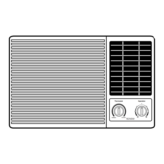
1.4 FEATURES • Powerful and quiet cooling. • Slide-in and slide-out chassis for the simple installation and service. • Reversible inlet grille. • Side air-intake, side cooled-air discharge. • Built in adjustable THERMOSTAT. • Washable one-touch filter. • Compact size. •... -
Page 6: Disassembly Instructions
2. DISASSEMBLY INSTRUCTIONS — Before the following disassembly, POWER SWITCH set to OFF and disconnect the power cord. 2.1 MECHANICAL PARTS 2.1.1 FRONT GRILLE 1. Open the lnlet grille upward or downward. 2. Remove the screw which fastens the front grille. 3. -
Page 7: Air Handling Parts
2.2 AIR HANDLING PARTS 2.2.1 AIR GUIDE AND BLOWER 1. Remove the front grille. (Refer to section 2.1.1) 2. Remove the cabinet. (Refer to section 2.1.2) 3. Remove the control box. (Refer to section 2.1.3) 4. Remove the 3 screws which fasten the brace. 5. -
Page 8: Electrical Parts
2.3 ELECTRICAL PARTS 2.3.1 OVERLOAD PROTECTOR 1. Remove the cabinet. (Refer to section 2.1.2) 2. Remove the nut which fastens the terminal cover. 3. Remove the terminal cover. (See Figure 8) 4. Remove all the leads from the overload protector. 5. -
Page 9: Power Cord
2.3.4 POWER CORD 1. Remove the control box. (Refer to section 2.1.3) 2. Open the control box. (Refer to section 2.3.3) 3. Disconnect the grounding screw from the control box. 4. Disconnect the 2 receptacles. 5. Remove a screw which fastens the clip cord. (See Figure 11) 6. -
Page 10: Refrigeration Cycle
2.4 REFRIGERATING CYCLE CAUTION Discharge the refrigerant system using a Freon Recovery System. If there is no valve to attach the recovery system, install one (such as a WATCO A-1) before venting the Freon . Leave the valve in place after servicing the system. 2.4.1 CONDENSER 1. - Page 11 NOTES — Replacement of the refrigeration cycle. 6. Recharge as follows : 1. When replacing the refrigeration cycle, be sure to Discharge the refrigerant system using a Freon 1) Refrigeration cycle systems are charged from recovery System. the High-side. If the total charge cannot be put If there is no valve to attach the recovery system, in the High-side, the balance will be put in the install one (such as a WATCO A-1) before venting...
- Page 12 Equipment needed: Vacuum pump, Charging cylinder, Manifold gauge, Brazing equipment. Pin-off tool capable of making a vapor-proof seal, Leak detector, Tubing cutter, Hand Tools to remove components, Service valve. Figure 17B-Charging Figure 17A-Pulling Vacuum —11—...
-
Page 13: Installation
3. INSTALLATION 3.1 SELECT THE BEST LOCATION FENCE 1.To prevent vibration and noise, make sure the unit AWNING is installed securely and firmly. COOLED AIR 2.Install the unit where the sunlight does not shine HEAT directly on the unit. RADIATION 3.The outside of the cabinet must extend outward for at least 11"... -
Page 14: How To Install
3.4 HOW TO INSTALL 3.4.1 WHEN USING GASKET RIGHT SIDE HORIZONTAL LINE 1. WINDOW (WIDTH-A, HEIGHT-B) 4. DETAILS 5.1 x 30 ROUND HEAD WOOD SCREWS 2. GASKET 3. WALL 495mm 366mm 250mm 30mm 0~25mm OVER 420mm 12mm 32mm 5~10mm 0~5mm ") ") (10") -
Page 15: Preparation Of Chassis
SUGGESTED TOOL REQUIREMENTS SCREWDRIVER(+, -), RULER, KNIFE, HAMMER, PENCIL, LEVEL PREPARATION OF CHASSIS Shipping 1. Remove the screws which fasten the cabinet at both Screws sides and at the back. 2. Slide the unit from the cabinet by gripping the base pan handle and pulling forward while bracing the cabinet. - Page 16 3. Loosely assemble the sill support using the parts in Figure 22. INDOOR OUTDOOR Sill Support Figure 22 Bolt 4. Select the position that will place the sill support near the outer most point on sill (See Figure 23) Frame Guide Screw(Type A) NOTE: Be careful when you install the cabinet (frame guides...
- Page 17 10. Slide the unit into the cabinet.(See Figure 26) CAUTION: For security purpose, reinstall screws(Type Power cord A) at cabinet's sides. Screw(Type A) Screw(Type A) Figure 26 11. Cut the foam-strip to the proper length and insert between the upper window sash and the lower window sash.
-
Page 18: How To Use The Reversible Inlet Grille
3.5 HOW TO USE THE REVERSIBLE INLET GRILLE 1. If you want to pull out the filter upward, open the inlet grille slightly. Turn inside out the front grille. Disassemble the inlet grille from the front grille with separating the hinged part by inserting a "—" type screw-driver tip. -
Page 19: Outside Dimensions
4. TROUBLESHOOTING GUIDE 4.1 OUTSIDE DIMENSIONS unit: mm(inch) 525(20 ") 470(18 ") 4.2 PIPING SYSTEM CONDENSER COIL CAPILLARY TUBE MOTOR COMPRESSOR BLOWER EVAPORATOR COIL Following is a brief description of the important components and their function in what is called the refrigeration system. -
Page 20: Troubleshooting Guide
4.3 TROUBLESHOOTING GUIDE In general, possible trouble is classified in two kinds. The one is called Starting Failure which is caused from an electrical defect, and the other is ineffective Air Conditioning caused by a defect in the refrigeration circuit and improper application. Unit runs but poor cooling. - Page 21 Fails to Start Check of power source. Check circuit breaker and fuse. Check of control switch Gas leakage of feeler bulb setting. of thermostat Check of control switch. Compressor only fails to Fan only fails to start. start. Improper wiring. Drop of power voltage.
- Page 22 ROOM AIR CONDITIONER VOLTAGE LIMITS NAME PLATE RATING MINIMUM MAXIMUM 115V ± 10% 103.5V 126.5V COMPLAINT CAUSE REMEDY Check voltage at outlet. Correct if none. Fan motor will not run. No power Check voltage to rotary switch. If none, check Power supply cord power supply cord.
- Page 23 COMPLAINT CAUSE REMEDY Fan motor noise. If cracked, out of balance, or partially missing, replace it. Blower If cracked, out of balance, or partially missing, replace it. Loose clamper Tighten it. Worn bearings If knocking sounds continue when running or loose, replace the motor.
- Page 24 REMEDY COMPLAINT CAUSE Fan motor Compressor cycles on If not running, determine the cause. Replace if overload(Cont’d) required. Condenser air flow Remove the cabinet. inspect the interior surface restriction of the condenser; if restricted, clean carefully with a vacuum cleaner (do not damage fins) or brush.
-
Page 25: Circuit Diagram
5. CIRCUIT DIAGRAM POWER INPUT BK(BR) WH(BL) (Plain) (Ribbed) ROTARY SWITCH GN(GN/YL) RD(BL) BL(RD) BL(RD) MOTOR OR(BR) CAPACITOR OR(BR) WH(BR) BK(BR) THERMOSTAT ROCKER SWITCH SYNC. MOTOR COMP BR(YL) O.L.P FUSE LINK HEATER BI-METAL WIRING DIAGRAM 3854AR3563D THERMOSTAT DESCRIPTION POWER CORD ROTARY SWITCH FAN MOTOR CAPACITOR... -
Page 26: Exploded View
6. EXPLODED VIEW —25—... -
Page 27: Replacement Parts List
7. REPLACEMENT PARTS LIST • MODEL: HBLG7000H R: Service Parts N: Non Service Parts PART NO. SERIAL Q'TY DESCRIPTION PER SET MARK HBLG7000H 135312 FRONT GRILLE ASSEMBLY 3531A10128B 135313 INLET GRILLE 3530A10027A 152302 AIR FILTER ASSEMBLY 5231A20004A 147581 HORIZONTAL LOUVER... - Page 28 R: Service Parts N: Non Service Parts PART NO. SERIAL Q'TY DESCRIPTION PER SET MARK HBLG7000H 35211A SUCTION TUBE ASSEMBLY 5211A20130A 352113 DISCHARGE TUBE 5210A20119D 352115 TUBE FORMED ASSEMBLY, EVAP. IN 5211A20131H 552113 TUBE ASSEMBLY, COND. OUT 5211AR3399A 552111 TUBE, CAPILLARY BENT...
- Page 29 January, 2005 Printed in Korea P/No. : 3828A20140W...
Need help?
Do you have a question about the HBLG7000H and is the answer not in the manual?
Questions and answers