Table of Contents
Advertisement
Quick Links
Advertisement
Table of Contents

Related Manuals for DFI QCS051


Summary of Contents for DFI QCS051
- Page 1 QCS051 2.5" Pico-ITX Motherboard User’s Manual © November 08, 2024 DFI Inc.
-
Page 2: Fcc And Doc Statement On Class B
1. The changes or modifications not expressly approved by the party responsible for com- are the properties of the respective owners. pliance could void the user’s authority to operate the equipment. 2. Shielded interface cables must be used in order to comply with the emission limits. User's Manual | QCS051... -
Page 3: Table Of Contents
Installing the M.2 Module .....................19 Chapter 3 - Software User Guide ....................21 Flash Images with Fastboot ....................21 Software Feature ........................22 Introduction ........................22 Develop Environment ....................22 General Support ......................22 Linux AP/API Support List ....................22 Ubuntu Support List ......................23 User's Manual | QCS051... -
Page 4: About This Manual
• To reduce the risk of electric shock, unplug the power cord before removing the sys- tem chassis cover for installation or servicing. After installation or servicing, cover the system chassis before plugging the power cord. User's Manual | QCS051... -
Page 5: About The Package
This may differ in accordance with the sales region or models in which it was sold. For more information about the standard package in your region, please contact your dealer or sales repre- sentative. User's Manual | QCS051... -
Page 6: Chapter 1 - Introduction
1 x uSD3.0 card Camera 2 x MIPI-CSI2 for 4-lanes camera, reference to IMX577 Other I/O 1 x Ext. IO (1*12P/1.25mm), 1 x Power LED, 1 x System LED, 1 x Front Panel 1 x Fan connector (upon request) User's Manual | QCS051... - Page 7 Operating: 5 to 90% RH Storage: 5 to 90% RH MECHANISM Dimensions 2.5" Pico-ITX Form Factor: 100mm (3.94") x 72mm (2.83") Height PCB: 1mm Top Side: TBD, Bottom Side: TBD STANDARDS AND Certifications CE, FCC, RoHS, UKCA CERTIFICATIONS User's Manual | QCS051...
-
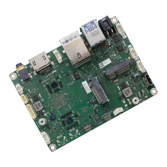
Page 8: Chapter 2 - Hardware Installation
Chapter 2 HARDWARE INSTALLATION Chapter 2 - Hardware Installation X Board Layout Top View Bottom View 1 (+5V) M.2 E Key User's Manual | QCS051... - Page 9 Battery USB Type C (Download only) COM1 Camera1 DIO 8-bits Camera2 CAN FD Force USB Boot Audio USB2.0_Debug/Console HDMI USB2.0_ADB USB2.0_4 SPI/I2C/GPIO SIM Slot USB3.0 Gen1 USB Boot (SW1) DC-IN uSD Slot USB2.0_2 Front Panel USB2.0_1 User's Manual | QCS051...
-
Page 10: Pin Assignment
Chapter 2 HARDWARE INSTALLATION X Pin Assignment Battery (BTJ1) DC-IN (DCCN1) 1 (+5V) 1 (+5V) 1 (+5V) M.2 E Key M.2 E Key Assignment Assignment +VBAT User's Manual | QCS051... -
Page 11: Force Usb Boot (Swj1)
Force_USB_Boot SW1_PU_1P8 Assignment USB-DN Note: USB-DP SWJ1, internal wafer, is saved for system integration. Same function as SW1. To enter the download mode (USB Boot), you can just press SW1 or have SWJ1 two pins short-circuted. User's Manual | QCS051... -
Page 12: Usb2.0_2 (Ubj2)
Chapter 2 HARDWARE INSTALLATION USB2.0_4 (UBJ4) USB2.0_2 (UBJ2) 1 (+5V) 1 (+5V) M.2 E Key M.2 E Key Assignment Assignment USB-DN USB-DN USB-DP USB-DP User's Manual | QCS051... -
Page 13: Can Fd (Cbj1)
Chapter 2 HARDWARE INSTALLATION COM1 (TSJ1) CAN FD (CBJ1) 1 (+5V) 1 (+5V) M.2 E Key M.2 E Key Assignment Assignment +VDD_CAN COM1_RX COM1_TX CAN1H COM1_CTS CAN1L COM1_RTS User's Manual | QCS051... -
Page 14: Usb2.0_Adb (Ubcn4)
Chapter 2 HARDWARE INSTALLATION USB2.0_Debug/Console (DUCN1) USB2.0_ADB (UBCN4) Assignment Assignment USB-DN USB-DN USB-DP USB-DP User's Manual | QCS051... -
Page 15: Front Panel (Fpj1) Dio 8-Bits (Ioj1)
Chapter 2 HARDWARE INSTALLATION DIO 8-bits (IOJ1) Front Panel (FPJ1) 1 (+5V) M.2 E Key Assignment Assignment DIO0 DIO1 DIO2 Volume-_Button# DIO3 Volume+_Button# DIO4 DIO5 PWR_Button# DIO6 LED_3.3V DIO7 +VPWR_3.3V User's Manual | QCS051... -
Page 16: Spi/I2C/Gpio (Ioj2)
Chapter 2 HARDWARE INSTALLATION SPI/I2C/GPIO (IOJ2) Assignment +VCC_3.3V SPI_MISO_3V3 SPI_MOSI_3V3 SPI_CLK_3V3 SPI_CS#_3V3 I2C_SCL_3V3 I2C_SDA_3V3 GPIOA_3V3 GPIOB_3V3 GPIOC_3V3 User's Manual | QCS051... -
Page 17: Camera 1 (Cmj1)
HARDWARE INSTALLATION Camera 1 (CMJ1) Assignment Assignment CAM2_Strobe/ CAM2_SPI-CLK GPIO +2.8V CAM2_SPI-MOSI 1 (+5V) CAM2_RESET# CAM2_CSI_D2P CAM2_CSI_D2M CAM2_CSI_D0P M.2 E Key CAM2_CSI_D0M CAM2_CSI_D3P CAM2_CSI_D3M Reserved CAM2_CSI_D1M CAM2_CSI_D1P CAM2_CSI_CKM CAM2_CSI_CKP CAM2_CSI_MCLK CAM2_I2C-SCL CAM2_I2C-SDA CAM2_SPI-CS# +1.8V CAM2_SPI-MISO +1.1V User's Manual | QCS051... -
Page 18: Camera 2 (Cmj2)
HARDWARE INSTALLATION Camera 2 (CMJ2) Assignment Assignment CAM0_Strobe/ CAM0_RSV#1 GPIO +2.8V CAM0_RSV#2 1 (+5V) CAM0_RESET# CAM0_CSI_D2P CAM0_CSI_D2M CAM0_CSI_D0P M.2 E Key CAM0_CSI_D0M CAM0_CSI_D3P CAM0_CSI_D3M Reserved CAM0_CSI_D1M CAM0_CSI_D1P CAM0_CSI_CKM CAM0_CSI_CKP CAM0_CSI_MCLK CAM0_I2C-SCL CAM0_I2C-SDA CAM0_RSV#4 +1.8V CAM0_RSV#3 +1.1V User's Manual | QCS051... -
Page 19: Expansion Slots
4. Make sure the notch on card is aligned to the key on the socket. 5. Make sure the standoff screw is removed from the standoff. M.2 E Key M.2 Module M.2 Socket Stand-off Notch M.2 B-Key M.2 E-Key User's Manual | QCS051... - Page 20 Screw tight the card onto the stand-off with a screw driver and a stand-off screw until the gap between the card and the stand-off closes up. The card should be lying parallel to the board when it’s correctly mounted. User's Manual | QCS051...
-
Page 21: Chapter 3 - Software User Guide
3.2. Enter application processor location and copy abl/boot/sysfs three images to the local folder. $ cd <extract_folder>/qcs051_meta/apps_proc/build-qti-distro-ubuntu-fullstack-debug/tmp-glibc/ deploy/images/qcs6490-odk 3.3. Run the following commands to flash: $ fastboot flash abl abl.elf $ fastboot flash boot qti-ubuntu-robotics-image-qcs6490-odk-boot.img $ fastboot flash system qti-ubuntu-robotics-image-qcs6490-odk-sysfs.ext4 $ fastboot reboot User's Manual | QCS051... -
Page 22: Software Feature
Linux systems. 2024 Q2 5.4.254 Support wayland weston graphics Demo Ubuntu 20.04 kernel 5.4.254 image for QCS051 project was built with PC Ubuntu environment. Image Only (*). General Support Qualcomm QCS6490 All library and utility should support (*). -
Page 23: Ubuntu Support List
Support Linux “date -s”and “hwclock -w” console commands to set system time. 1. Support system sound output to LINE OUT Connector. Audio 2. Support GStreamer for test play MP3/WAV file. 3. Support sound recorder for test recording audio file. User's Manual | QCS051... - Page 24 (1) Support Wifi STA Mode (connect Wifi AP) (2) Not support Soft AP Mode. Support Quectel RM502Q-AE module 5G data-link function only. 5G module Image Size Around ~ 7.3GB (zip file) Free storage size Around ~ 92GB free space (/dev/root) User's Manual | QCS051...
Need help?
Do you have a question about the QCS051 and is the answer not in the manual?
Questions and answers