Advertisement
Quick Links
FORM HANDLE
TUBE
CLAMP
1. Raise form handle. (Fig. 1)
2. Position tubing in groove as shown.
Also be sure that the tube is engaged
with the tube clamp.
3. Lower the form handle to position
shown. (Fig. 2)
4. Pull lever handle to direction of arrow
until the desired bend is obtained.
FORM
HANDLE
X
USE "L" MARK
0
45
90
135
180
FORM WHEEL
FIGURE 3
90° Bends
1. Measure from end of tube (first bend) and place mark on tubing.
2. Position tube in bender as shown in Fig. 3. If the end from which you
measured is left of the tube clamp, the measured mark should be directly
over graduation "L" located on the right side of the form lever and shown
in Fig. 3.
3. If the end from which you measured is placed to the right clamp, set the
mark on the tube directly over graduation "R" located on the form lever and
shown in Fig. 4. With a steady motion, pull form lever handle around until
the "0" mark on form handle is directly opposite the 90° mark on form wheel.
4. If more than one bend is required (Fig. 5), measure from the center line
of the first bend leg and mark per drawing dimension. Proceed with bend
as described in Step 2.
Reed Manufacturing Company
1425 West 8th Street
Erie, PA 16502 USA
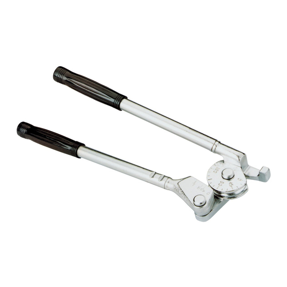
Instructions For Operating Lever Type Tube Benders
This bender can be used for bending steel, stainless steel, copper, aluminum and other metal tubing of bending
temper. Extremely thin walled and/or hard temper tubing should be avoided.
BENDER SETUP
TUBING
0
45
FORM
90
135
WHEEL
180
FORM
WHEEL
HANDLE
FIGURE 1
USE THIS
MARK FOR
DEGREES
OF BEND
0
45
90
135
180
X
FORM
HANDLE
TUBE
CLAMP
0
45
USE THIS MARK
90
135
180
FORM WHEEL
FIGURE 4
X
45° Bends
A single 45° bend may be made by measuring from end of tube to where
bend is to be located and placing a mark at this point. Place tube in bender
so that the mark on tube is located directly in line with the "45" graduation
on form handle shown in Fig. 6.
dOuBLe 45° Or 30° OFFseT Bends
When forming a tube offset, it is necessary to make two bends. It is important
to mark the tube at both bend locations before proceeding. After marking
the tube, proceed as explained under "45° BENDS".
TB04, TB06, TB08
PULL HANDLE THIS DIRECTION
FIGURE 2
5. Degree of bend is indicated by mark on
form handle and shown in Fig. 2. Bends
up to 180° can be made in one sweep of
the handle.
X
FIGURE 5
X
Phone: 800-666-3691 or 814-452-3691
Fax: 800-456-1697 or 814-455-1697
www.reedmfgco.com
X
0413-56450
Advertisement

Related Manuals for REED TB04


Summary of Contents for REED TB04
- Page 1 Instructions For Operating Lever Type Tube Benders TB04, TB06, TB08 This bender can be used for bending steel, stainless steel, copper, aluminum and other metal tubing of bending temper. Extremely thin walled and/or hard temper tubing should be avoided. BENDER SETUP...
- Page 2 4 eAsY sTePs FOr FIGurInG OFFseT Bends FOr TB04, TB06, TB08 USE “45”MARK MARK "A" OFFSET MARK "B" "Y" DIMENSION "Z" DIMENSION FIGURE 6 FIGURE 6 FIGURE 7 OFFseT Bend CALCuLATOr sTeP 1 — Determine the total amount of offset required (dimension “Y”...
Need help?
Do you have a question about the TB04 and is the answer not in the manual?
Questions and answers