Table of Contents
Advertisement
Quick Links
40MULA
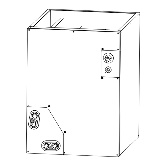
Fig. 1 - Evaporator A Coil (40MULAQ24XAX and
40MULAQ36XBX)
Fig. 2 - Evaporator A Coil (40MULAQ24XBX,
40MULAQ36XCX, 40MULAQ48XCX, 40MULAQ60XDX
NOTE: Read the entire instruction manual before starting the
installation.
NOTE: Images are for illustration purposes only. Actual models
may differ slightly.
Split Horizontal - Vertical Duct Air Conditioner
Installation Instructions
Specifications subject to change without notice.
TABLE OF CONTENTS
SAFETY CONSIDERATIONS........................................................2
INTRODUCTION ............................................................................5
DIMENSIONS..................................................................................6
REFRIGERANT COIL SPECIFICATIONS....................................9
INSTALLATION .............................................................................10
EVAPORATOR FLANGE FABRICATION...................................11
SENSOR INSTALLATION.............................................................15
OPERATION MODE SETTING .....................................................17
AIR FLOW SPECIFICATIONS ......................................................17
CARE AND MAINTENANCE........................................................17
Sizes 24K-60K
PAGE
Advertisement
Table of Contents

Subscribe to Our Youtube Channel
Related Manuals for Carrier 40MULA


Summary of Contents for Carrier 40MULA
-
Page 1: Table Of Contents
40MULA Split Horizontal - Vertical Duct Air Conditioner Sizes 24K-60K Installation Instructions TABLE OF CONTENTS PAGE SAFETY CONSIDERATIONS............2 INTRODUCTION ................5 DIMENSIONS..................6 REFRIGERANT COIL SPECIFICATIONS........9 INSTALLATION ................10 EVAPORATOR FLANGE FABRICATION........11 SENSOR INSTALLATION.............15 OPERATION MODE SETTING .............17 AIR FLOW SPECIFICATIONS ............17 CARE AND MAINTENANCE............17 Fig. -
Page 2: Safety Considerations
40MULA: Installation Instructions SAFETY CONSIDERATIONS WARNING Improper installation, adjustment, alteration, service, maintenance, or use can cause explosion, fire, electrical shock, or other conditions which may cause death, personal injury or property damage. If an abnormal situation occurs (like a burning smell), immediately turn off the unit and disconnect the power. -
Page 3: Electrical Warnings
40MULA: Installation Instructions WARNING WARNING ELECTRICAL WARNINGS PRODUCT INSTALLATION WARNINGS Installation must be performed by an authorized dealer or specialist. Only use the specified power cord. If the power cord is damaged, it must Defective installation can cause water leak, electrical shock, or fire. - Page 4 40MULA: Installation Instructions Table 1 — Model Numbers KBTUH VOLTAGE MODEL # 208/230-1-60 40MULAQ24XAX 208/230-1-60 40MULAQ24XBX 208/230-1-60 40MULAQ36XBX 208/230-1-60 40MULAQ36XCX 208/230-1-60 40MULAQ48XCX 208/230-1-60 40MULAQ60XDX (1) (2) (1). A-COIL (40MULAQ) (2). Pipe temperature sensor( T2) (3). Drain pan (4). Condensate drain connection (5).
-
Page 5: Introduction
40MULA: Installation Instructions INTRODUCTION Use this instruction manual to install indoor coil on multi-purpose furnaces. The coil is enclosed in a casing. Supply Return Horizontal Left Furnace Installation Evaporator Coil Return Supply Horizontal Right Furnace Installation Fig. 4 — Left and Right Installation... -
Page 6: Dimensions
40MULA: Installation Instructions DIMENSIONS Table 2 — Dimensions and Weights MODEL # 40MULAQ24XAX 40MULAQ24XBX 40MULAQ36XBX 40MULAQ36XCX 40MULAQ48XCX 40MULAQ60XDX DIMENSIONS Height (A) 17.99 (457) 17.99 (457) 23.58 (599) 23.98 (609) 23.98 (609) 27.99 (711) (mm) Width (B) 14.49 (368) 17.52 (445) 17.52 (445) - Page 7 40MULA: Installation Instructions Fig. 6 — 40MULAQ24XAX, 40MULAQ36XBX Manufacturer reserves the right to change, at any time, specifications and designs without notice and without obligations.
- Page 8 40MULA: Installation Instructions Fig. 7 — 40MULAQ24XBX, 40MULAQ36XCX, 40MULAQ48XCX, 40MULAQ60XDX Manufacturer reserves the right to change, at any time, specifications and designs without notice and without obligations.
-
Page 9: Refrigerant Coil Specifications
40MULA: Installation Instructions REFRIGERANT COIL SPECIFICATIONS Table 3 — Refrigerant Coil Specifications MODEL NUMBER 40MULAQ24XAX 40MULAQ24XBX 40MULAQ36XBX 40MULAQ36XCX 40MULAQ48XCX 40MULAQ60XDX Number of rows Rows inch 0.276 0.276 0.276 0.276 0.276 0.276 Tube outside diameter. inch 0.039 0.039 0.039 0.039 0.039 0.039... -
Page 10: Installation
40MULA: Installation Instructions INSTALLATION Upflow Coil Installation The cased coil is designed to fit furnaces of the same width. 1. Set the coil in place on the upflow furnace discharge air opening. 2. Ensure the coil is level for proper condensate drainage. Do not tip coil toward condensate drain. Coil casing does not need not be fastened or screwed to furnace. -
Page 11: Evaporator Flange Fabrication
40MULA: Installation Instructions EVAPORATOR FLANGE FABRICATION 1. Using 26 gauge sheet metal and sheet metal snips, cut flange sections 1" high for the sides and back. 2. For the front, cut a 2" high section with a 1" break to attach to the top of the front section of the cabinet. -
Page 12: Horizontal Right Installation
40MULA: Installation Instructions Adapter(s) Installation When Coil Hangs Over the Horizontal Coil Installation The unit can be installed on a work platform, secured to roof truss in the Furnace attic, suspended from hangers on the floor joists in crawl space, or installed on blocks. -
Page 13: Refrigerant Line Connections
40MULA: Installation Instructions Refrigerant Line Connections 1. Remove the cabinet access door. 2. Remove the rubber plugs, the suction plug then the liquid plug, from the coil stubs using a pulling and twisting motion. Hold coil stubs WARNING steady to avoid bending or distorting. -
Page 14: Refrigerant Metering Device
40MULA: Installation Instructions Refrigerant Metering Device Condensate Drain Line Connection These coils have a factory installed hard shut-off TXV designed only for use with R-410A refrigerant. Use only with outdoor units designed for R-410A. CAUTION NOTE: All TXV’S have preset superheat settings and are field non- Failure to follow this caution may result in property damage. -
Page 15: Sensor Installation
40MULA: Installation Instructions SENSOR INSTALLATION To Install the T1 Sensor: 1. Use a 1/4” drill bit (or Unibit) to drill an opening in the return plenum. The distance of the T1 location should be within the 16' of the T1 extension wire provided. - Page 16 40MULA: Installation Instructions WARNING Air Gap Above Liquid Level Failure to follow this warning could result in personal injury or death. Provide trap with an air gap in the drain line when connecting to waste (sewer) line. Condensate Line Trap Sewer Line Fig.
-
Page 17: Operation Mode Setting
40MULA: Installation Instructions OPERATION MODE SETTING Refer to the KSACN1101AAA Installation Manual S3 table on page 11 for setting the S3 dial on the interface for compressor drop out temperature for dual fuel. For wired controller dual fuel operation, set the heat mode to “HEAT + AUX” to operate the heat for dual fuel. - Page 18 40MULA: Installation Instructions © 2024 Carrier. All rights reserved. Edition Date: 02/24 Catalog No: 40MULA-01SI Replaces: NEW Manufacturer reserves the right to change, at any time, specifications and designs without notice and without obligations.
Need help?
Do you have a question about the 40MULA and is the answer not in the manual?
Questions and answers