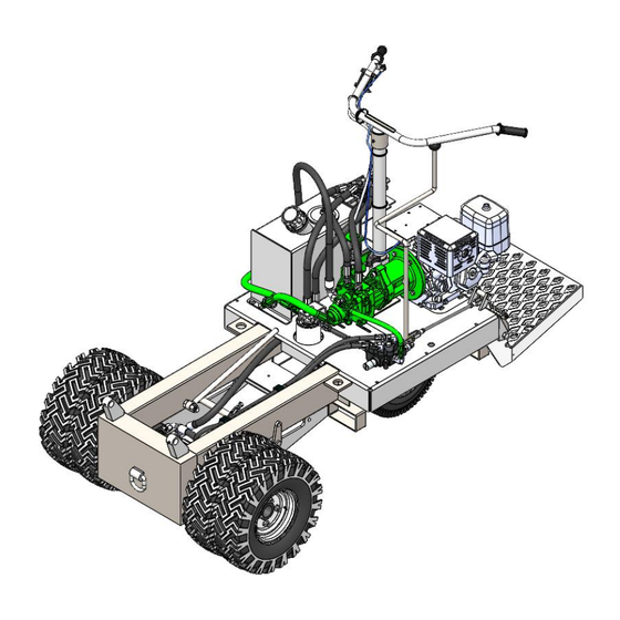
MULTIQUIP WBH16EF Instructions Manual
Buggie, hydro-gear pump & system bleeding
Hide thumbs
Also See for WBH16EF:
- Operation and parts manual (82 pages) ,
- Operation and parts manual (82 pages) ,
- Operation manual (48 pages)
Advertisement
Quick Links
HYDRO-GEAR PUMP & SYSTEM BLEEDING INSTRUCTIONS
This document is for assisting the technician in bleeding the hydraulic pump and system after installing a
new Hydro-Gear pump.
Safety First:
✓ To avoid injury, read and understand Operator's Manual before working on this machine.
✓ Follow safety lock-out tag-out procedures:
• Remove ignition key
•
Disconnect battery cables
✓ Intended for experienced qualified technicians only
✓ DO NOT open hydraulic lines or loosen fittings while the engine is running, hydraulic oil can
penetrate the skin, blind and cause burns
✓ Always wear safety glasses and appropriate attire
Tools Needed:
• Sockets and ratchet set
• Wrench set
• Allen Wrench set
PRODUCT: BUGGIES
MODEL: WBH16EF
Advertisement

Subscribe to Our Youtube Channel
Summary of Contents for MULTIQUIP WBH16EF
- Page 1 PRODUCT: BUGGIES MODEL: WBH16EF HYDRO-GEAR PUMP & SYSTEM BLEEDING INSTRUCTIONS This document is for assisting the technician in bleeding the hydraulic pump and system after installing a new Hydro-Gear pump. Safety First: ✓ To avoid injury, read and understand Operator’s Manual before working on this machine.
- Page 2 PRODUCT: BUGGIES MODEL: WBH16EF HYDRO-GEAR PUMP & SYSTEM BLEEDING INSTRUCTIONS Bleeding Air from Hydro-Gear Pump Important Preliminary Steps ✓ If needed, add SAE 15W-40 motor oil to reservoir to level with the (black line) on sight glass ✓ Place machine off the ground on jack stands ✓...
- Page 3 PRODUCT: BUGGIES MODEL: WBH16EF HYDRO-GEAR PUMP & SYSTEM BLEEDING INSTRUCTIONS Bleeding Air from Hydro-Gear Pump Step 4: Pull the engine’s starter rope multiple times to rotate the pump and purge air from the auxiliary pump (F) Step 5: Once the air is purged/no air bubbles are visible, install the port plug back in place (G)
-
Page 4: Bleeding Air From Hydraulic System
PRODUCT: BUGGIES MODEL: WBH16EF HYDRO-GEAR PUMP & SYSTEM BLEEDING INSTRUCTIONS Bleeding Air from Hydraulic System IMPORTANT: FIRST BLEED THE HYDRO-GEAR PUMP BEFORE PERFORMING THIS PROCEDURE Step 1: Slightly crack open/loosen hose fitting (A) Step 2: Activate the directional valve lever to either forward or revers (B) Step 3: Activate/squeeze the travel lever (C) and while activated, pull the engine starter rope multiple times (D) or use electric start to purge air from the (cracked) hose fitting. - Page 5 PRODUCT: BUGGIES MODEL: WBH16EF HYDRO-GEAR PUMP & SYSTEM BLEEDING INSTRUCTIONS Bleeding Air from Hydraulic Cylinder IMPORTANT: FIRST BLEED THE HYDRO-GEAR PUMP BEFORE PERFORMING THIS PROCEDURE Step 1: Slightly crack open/loosen hose fitting (A) at the dump valve Step 2: Activate the dump lever (B) to the forward/dump position and hold Step 3: Pull the engine starter rope multiple times (C) or use electric start to purge air from the (cracked) hose fitting.
- Page 6 PRODUCT: BUGGIES MODEL: WBH16EF HYDRO-GEAR PUMP & SYSTEM BLEEDING INSTRUCTIONS Pump – Neutral Lever Adjustment Step 1: (A) Loosen the speed control cable jam nuts from hydraulic tank bracket (B). Step 2: Adjust speed control cable jam nuts until pump activation lever is set to neutral position.


Need help?
Do you have a question about the WBH16EF and is the answer not in the manual?
Questions and answers