Table of Contents
Advertisement
Quick Links
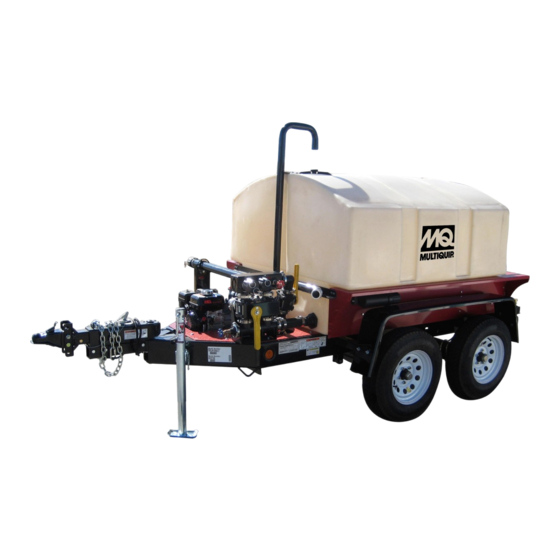
OPERATION MANUAL
WT5CSG/WTE5CSG
WT5CYC/WTE5CYC
WATER TRAILERS
(HONDA GX120UT3PX2 GASOLINE ENGINE)
(QP2HLF CENTRIFUGAL PUMP)
To find the latest revision of this publication or
associated parts manual, visit our website at:
THIS MANUAL MUST ACCOMPANY THE EQUIPMENT AT ALL TIMES.
MODELS
WT5C/WTE5C
Revision #6 (05/28/21)
www.multiquip.com
PN 49858
Advertisement
Table of Contents

Related Manuals for MULTIQUIP WTE5CSG


Summary of Contents for MULTIQUIP WTE5CSG
- Page 1 OPERATION MANUAL MODELS WT5C/WTE5C WT5CSG/WTE5CSG WT5CYC/WTE5CYC WATER TRAILERS (HONDA GX120UT3PX2 GASOLINE ENGINE) (QP2HLF CENTRIFUGAL PUMP) Revision #6 (05/28/21) To find the latest revision of this publication or associated parts manual, visit our website at: www.multiquip.com THIS MANUAL MUST ACCOMPANY THE EQUIPMENT AT ALL TIMES.
-
Page 2: Proposition 65 Warning
PROPOSITION 65 WARNING PAGE 2 — WT5C SERIES WATER TRAILER • OPERATION MANUAL — REV. #6 (05/28/21) - Page 3 NOTES WT5C SERIES WATER TRAILER • OPERATION MANUAL — REV. #6 (05/28/21) — PAGE 3...
-
Page 4: Table Of Contents
TABLE OF CONTENTS WT5C Series Water Trailer Proposition 65 Warning ........... 2 Table Of Contents ............ 4 Safety Information ..........5–9 Specifications (Pump/Trailer) ......... 10 Specifications (Engine) .......... 11 Dimensions ............12 General Information ..........13 Components (Water Trailer) ......14–15 Basic Engine ............ -
Page 5: Safety Information
SAFETY INFORMATION Do not operate or service the equipment before reading Potential hazards associated with the operation of this the entire manual. Safety precautions should be followed equipment will be referenced with hazard symbols which at all times when operating this equipment. may appear throughout this manual in conjunction with Failure to read and understand the safety safety messages. - Page 6 „ NEVER use accessories or attachments that are not „ Avoid wearing jewelry or loose-fi tting clothes that may recommended by Multiquip for this equipment. Damage snag on the controls or moving parts as this can cause to the equipment and/or injury to user may result.
- Page 7 SAFETY INFORMATION PUMP SAFETY „ ALWAYS store equipment properly when it is not being used. Equipment should be stored in a clean, dry location DANGER out of the reach of children and unauthorized personnel. „ NEVER operate the equipment in an explosive „...
- Page 8 SAFETY INFORMATION FUEL SAFETY „ ALWAYS inspect the hitch and coupling for wear. NEVER tow a trailer with defective hitches, couplings, chains, etc. DANGER „ Check the tire air pressure on both towing vehicle and „ DO NOT start the engine near spilled fuel or combustible trailer.
- Page 9 SAFETY INFORMATION ENVIRONMENTAL SAFETY/DECOMMISSIONING EMISSIONS INFORMATION NOTICE NOTICE Decommissioning is a controlled process used to safely The gasoline engine used in this equipment has been retire a piece of equipment that is no longer serviceable. designed to reduce harmful levels of carbon monoxide If the equipment poses an unacceptable and unrepairable (CO), hydrocarbons (HC) and nitrogen oxides (NOx) safety risk due to wear or damage or is no longer cost...
-
Page 10: Specifications (Pump/Trailer)
SPECIFICATIONS (PUMP/TRAILER) Table 1. Specifications Type Low Profile Style Rotomolded - Seamless with Baffles Fill Port 12" - Vented Port Material Polypropylene - 1/4" Wall - Repairable Water Tank Fill Rate 5 min. Full (Fill at Full Throttle) Capacity 525 gallons (1,987 liters) Weight w/ Empty Water Tank 1,530 lbs. -
Page 11: Specifications (Engine)
SPECIFICATIONS (ENGINE) Table 2. Specifications (Engine) Model Honda GX120UT3PX2 Air-cooled, 4-stroke, Single Cylinder, OHV, Type Horizontal Shaft Gasoline Engine Bore × Stroke 2.36 in. × 1.65 in. (60 mm × 42 mm) Displacement 7.2 cu-in. (118 cc) Max. Output 3.5 H.P. @ 3,600 RPM Fuel Tank Capacity 0.66 U.S. -
Page 12: Dimensions
DIMENSIONS REAR VIEW FRONT VIEW SIDE VIEW Figure 1. Dimensions Table 3. Dimensions Reference Dimension Reference Dimension Reference Dimension Reference Dimension Letter in (mm) Letter in (mm) Letter in (mm) Letter in (mm) 69.50 (1,765) 60.50 (1,537) 80.00 (2,032) 18.70 (475) 47.25 (1,200) 64.00 (1,626) 25.00 (635) -
Page 13: General Information
The Multiquip QP2HLF Centrifugal Pump, which is used „ Fire Hose Nozzle in conjunction with the water trailer, has the capability to Contact your nearest Multiquip dealer for any hoses or pump at a rate of approximately 158 gallons/minute (gpm) accessories that you may need. -
Page 14: Components (Water Trailer)
COMPONENTS (WATER TRAILER) Figure 2. Water Trailer Components PAGE 14 — WT5C SERIES WATER TRAILER • OPERATION MANUAL — REV. #6 (05/28/21) - Page 15 COMPONENTS (WATER TRAILER) 1. Water Tank — Capacity is 525 gallons (1,987 liters). 13. Fill Cap — Prior to operation, the pump casing should Fill with clean water with no debris. be filled with water. Remove this cap to add water to the pump.
-
Page 16: Basic Engine
BASIC ENGINE 3. Engine ON/OFF Switch — ON position permits engine starting, OFF position stops engine operations. 4. Recoil Starter (pull rope) — Manual starting method. Pull the starter grip until resistance is felt, then pull briskly and smoothly. 5. Fuel Valve Lever — OPEN to let fuel flow, CLOSE to stop the flow of fuel. -
Page 17: Inspection
INSPECTION ENGINE OIL CHECK FUEL CHECK 1. To check the engine oil level, place the unit on secure DANGER level ground with the engine stopped. Motor fuels are highly flammable and can be 2. Remove the filler dipstick from the engine oil filler hole dangerous if mishandled. -
Page 18: Operation
OPERATION STARTING THE ENGINE 5. Place the choke lever (Figure 9) in the OPEN position if starting a warm engine or the temperature is warm. 1. Place the manifold control handle in the vertical position (OFF). See Table 5. 2. Place the engine fuel valve lever (Figure 6) to the ON position. - Page 19 OPERATION Stopping The Engine 8. If the engine has started, and the choke lever was moved to the CLOSED position to start the engine, Normal Shutdown gradually move the choke lever to the OPEN position (Figure 9) as the engine warms up. If the engine has 1.
- Page 20 OPERATION Reference Figure 16 and Table 5 for the various control handle operating positions when using the Manifold and Spray Bar Control Handles. SPRAY BAR CONTROL HANDLE MANIFOLD CONTROL HANDLE Figure 16. Pump Control Handles Table 5. Pump Control Handle Operation Manifold Manifold Spray Bar...
- Page 21 OPERATION There is an operating mode (Figure 17) that could be NOTICE harmful to your water pump. Never operate the water trailer NEVER operate the water trailer with the spray bar and with the spray bar control handle in the vertical position (rear manifold control handles as shown in Figure 17.
- Page 22 OPERATION FILLING THE WATER TANK (FIRE HYDRANT) 7. Remove fire hydrant discharge hose and allow the hose to drain. Remove the hydrant adapter. 1. Remove the water tank cap. NOTICE 2. Attach hydrant adapter to fire hydrant if necessary. DO NOT attempt to connect fire hydrant discharge to 3.
- Page 23 OPERATION FILLING THE WATER TANK (WATER SOURCE) 6. Remove suction hose. 7. Install dust cap back onto male QD port. 1.5 or 2.0" CAM and Groove Male QD Port Garden Hose The following procedure shows how to fill the water tank using a swimming pool, pond, lake, river, etc.
- Page 24 OPERATION DISCHARGING WATER 3. Figure 20 represents a typical water discharge application utilizing the rear spray bar. The following procedure shows how to discharge water from the water tank using the CAM and groove male QD NOTICE couplers. Prior to engine start, the pump MUST BE primed. This 1.
-
Page 25: Winterizing Procedure
WINTERIZING PROCEDURE WINTERIZING 4. Rotate the manifold control handle to the 3 o'clock position (horizontal/right). See Figure 23. Perform the following procedure to protect water trailer from 5. Rotate the spray bar control handle to the 12 o'clock component damage in freezing temperature environments. position (vertical). - Page 26 WINTERIZING PROCEDURE 7. Once water appears to have all been drained, lower 9. Once fluid has stopped draining, reinstall the drain front trailer tongue by lowering front jack stand to the plug on pump end. lowest position (Figure 25). NOTICE It is important to cycle the manifold control handle from the 3 o'clock position then back to 9 o'clock position to TRAILER...
-
Page 27: Maintenance
MAINTENANCE PUMP VACUUM TEST CAUTION DO NOT attempt to start the engine unless the pump has previously been primed with water. Severe pump damage will occur if pump has not been primed. To perform the pump vacuum test do the following: 1. - Page 28 MAINTENANCE Use Table 6 as a general maintenance guideline when servicing your engine. For more detailed engine maintenance information, refer to the engine owner’s manual supplied with your engine. Table 6. Engine Maintenance Schedule EVERY FIRST EVERY 3 EVERY 6 EVERY 2 DESCRIPTION YEAR...
- Page 29 MAINTENANCE Perform the scheduled maintenance procedures as defined OIL FILLER DIPSTICK by Table 6 and below: DAILY „ Thoroughly remove dirt and oil from the engine and control area. Clean or replace the air cleaner elements as necessary. Check and retighten all fasteners as DRAIN SEALING BOLT...
- Page 30 MAINTENANCE STORAGE For storage of the unit for over 30 days, the following is required: „ Drain the fuel tank completely. „ Run the engine until the fuel in the carburetor is completely consumed. „ Completely drain used oil from the engine crankcase and fill with fresh clean oil, then follow the procedure described in the engine manual for engine storage.
- Page 31 MAINTENANCE The following trailer maintenance guidelines are intended 6. Replace the adjusting-hole cover. to assist the operator in preventive maintenance. 7. Repeat the above procedure on all brakes. TRAILER BRAKES 8. Lower the trailer to the ground. Properly functioning brake shoes and drums are essential Check the fluid level in the master cylinder reservoir at least to ensure safety.
- Page 32 MAINTENANCE „ Brake system has very little lag time between the time WARNING the vehicle’s brakes are actuated and the trailer’s brakes Failure to maintain proper fluid level in the actuator are actuated. may result in loss of braking action which could cause „...
- Page 33 MAINTENANCE ELECTRIC BRAKE ACTUATOR that the brakes apply to each wheel. You can do this by trying to pull the trailer with the tow vehicle, after pulling The electric brake actuator (Figure 34) is the mechanism the pin. The trailer brakes may not lock, but you will notice that activates the trailer’s brake system.
- Page 34 MAINTENANCE ADJUSTABLE CHANNEL If the trailer has not been used for an extended amount of time, have the bearings inspected and packed more Your trailer may be equipped with an adjustable channel frequently, at least every six months and prior to use. (Figure 35) that allows the coupler to be raised or lowered Follow the steps below to disassemble the wheel hub and to a desired height.
- Page 35 MAINTENANCE WHEEL HUB ADJUSTMENT WARNING Every time the wheel hub is removed and the bearings are If the trailer is involved in an accident, have it inspected reassembled, follow the steps below to check the wheel immediately by qualified personnel. In addition, the bearings for free running and adjust.
-
Page 36: Trailer Safety Guidelines
TRAILER SAFETY GUIDELINES The following guidelines are intended to assist the operator „ Shift your automatic transmission into a lower gear for in the operation and handling of a trailer. city driving. Safety precautions should be followed at all times when „... - Page 37 TRAILER SAFETY GUIDELINES DRIVING CONDITIONS for the use of your trailer. Again, be sure your hitch and tow vehicle are rated for the Gross Vehicle Weight Rating of When towing a trailer, you will have decreased acceleration, your trailer. increased stopping distance, and increased turning radius WARNING (which means you must make wider turns to keep from hitting curbs, vehicles, and anything else that is on the...
- Page 38 TRAILER SAFETY GUIDELINES INOPERABLE BRAKES, LIGHTS OR MIRRORS Drive slowly at fi rst, 5 mph or so, and turn the wheel to get the feel of how the tow vehicle and trailer combination Be sure that the brakes and all of the lights on your trailer responds.
- Page 39 TRAILER SAFETY GUIDELINES using an axle scale, you must know the axle weights of your tow vehicle without the trailer coupled. Some of the trailer weight will be transferred from the trailer to the tow vehicle axles, and an axle scale weighs all axles, including VIN TAG/ the tow vehicle axles.
- Page 40 TRAILER SAFETY GUIDELINES EMERGENCY FLARES AND TRIANGLE REFLECTORS BALL HITCH COUPLER It is wise to carry these warning devices even if you are A ball hitch coupler (Figure C) connects to a ball that is not towing a trailer. It is particularly important to have these located on or under the rear bumper of the tow vehicle.
- Page 41 TRAILER SAFETY GUIDELINES or is worn, the trailer can come loose from the tow vehicle the trailer tongue. Wood or concrete blocks may also be and may cause death or serious injury. used. THE TOW VEHICLE, HITCH AND BALL MUST HAVE A Coupling the Trailer to the Tow Vehicle (Ball Coupler) RATED TOWING CAPACITY EQUAL TO OR GREATER „...
- Page 42 TRAILER SAFETY GUIDELINES Breakaway Brake System NOTICE If the coupler or hitch fails, a properly connected and Overloading can damage the tongue jack. DO NOT working breakaway brake system (Figure F) will apply the use the tongue jack to raise the tow vehicle more than hydraulic brakes on the trailer.
- Page 43 TRAILER SAFETY GUIDELINES Connecting Trailer Lights PINTLE HITCH COUPLER Connect the trailer lights to the tow vehicle’s electrical A pintle eye coupler (Figure G) connects to a pintle-hook system using the electric connectors at the front of the hitch that is located on or under the rear bumper of the tow trailer (tongue).
- Page 44 TRAILER SAFETY GUIDELINES the ball andcoupler system. All bent or broken coupler parts WARNING must be replaced before towing the trailer. A defective pintle hitch not properly fastened can result THE TOW VEHICLE, PINTLE HITCH AND PINTLE in uncoupling, leading to death or serious injury. COUPLER MUST HAVE A RATED TOWING CAPACITY Be sure the pintle hook is securely tightened to the tow EQUAL TO OR GREATER THAN THE TRAILER Gross...
- Page 45 TRAILER SAFETY GUIDELINES TIRE SAFETY Lug nuts are also prone to loosen after first being assembled. When driving a new trailer (or after wheels Unsafe Tires, Lug Nuts or Wheels have been remounted), check to make sure they are tight after the fi rst 10, 25 and 50 miles of driving and before Trailer tires and wheels are more likely to fail than car tires each tow thereafter.
- Page 46 TRAILER SAFETY GUIDELINES Determining Load Limit of Tow Vehicle There is a vehicle placard (Figure I) located in the same location as the certifi cation label described above. This Step 1. placard provides tire and loading information. In addition, this placard will show a statement regarding maximum Locate the statement, “The combined weight of occupants cargo capacity.
- Page 47 TRAILER SAFETY GUIDELINES Use the information contained in this section to make tire M+S: The “M+S” or “M/S” indicates that the tire has safety a regular part of your vehicle maintenance routine. some mud and snow capability. Most radial tires have Recognize that the time you spend is minimal compared these markings;...
- Page 48 TRAILER SAFETY GUIDELINES Uniform Tire Quality Grading Standards (UTQGS) Load Range: This information identifi es the tire’s load- carrying capabilities and its infl ation limits. Treadwear Number: This number indicates the tire’s wear rate. The higher the treadwear number is, the longer it Tire Safety Tips should take for the tread to wear down.
- Page 49 TRAILER SAFETY GUIDELINES Table B below will help pinpoint the causes and solutions NOTICE of tire wear problems. NEVER use a pneumatic air gun to tighten wheel lug Table B. Tire Wear Troubleshooting nuts. Wear Pattern Cause Solution Over-tightening lug nuts will result in breaking the studs Adjust pressure to particular or permanently deforming the mounting stud holes in Center Wear...
- Page 50 TRAILER SAFETY GUIDELINES Replace any broken or burned-out lamps as necessary. Table C. Tire Torque Requirements Check the wire harness for cuts, fraying or other damage. First Pass Second Pass Third Pass If it needs replacing, contact your dealer. Wheel Size FT-LBS FT-LBS FT-LBS...
-
Page 51: Troubleshooting (Pump)
TROUBLESHOOTING Troubleshooting (Pump) Symptom Possible Problem Solution Check that proper voltage is being supplied to the pump. Also check that there is an adequate Incorrect voltage/amps? amount of current (amps) to run the pump. Check power source circuit breaker. If using fl oat switches check wiring, inspect Check electrical connections? power cord. -
Page 52: Troubleshooting (Engine)
TROUBLESHOOTING Troubleshooting (Engine) Symptom Possible Problem Solution Spark plug bridging? Check gap, insulation or replace spark plug. Carbon deposit on spark plug? Clean or replace spark plug. Short circuit due to defi cient spark plug Check spark plug insulation, replace if worn. insulation? Improper spark plug gap? Set to proper gap. - Page 53 NOTES WT5C SERIES WATER TRAILER • OPERATION MANUAL — REV. #6 (05/28/21) — PAGE 53...
- Page 54 © COPYRIGHT 2021, MULTIQUIP INC. Multiquip Inc , the MQ logo are registered trademarks of Multiquip Inc. and may not be used, reproduced, or altered without written permission. All other trademarks are the property of their respective owners and used with permission.
Need help?
Do you have a question about the WTE5CSG and is the answer not in the manual?
Questions and answers