
Related Manuals for Gigabyte GA-M61SME-S2


Summary of Contents for Gigabyte GA-M61SME-S2
- Page 1 GA-M61SME-S2 AMD Athlon 64 FX / Athlon 64 X2 Dual-Core / AMD Athlon 64 / Sempron AM2 Processor Motherboard User's Manual Rev. 2002 12ME-M61SMES2-2002R...
- Page 3 Gigabyte's prior written permission. Specifications and features are subject to change without prior notice. Product Manual Classification In order to assist in the use of this product, Gigabyte has categorized the user manual in the following: For detailed product information and specifications, please carefully read the "Product User Manual".
-
Page 4: Table Of Contents
Table of Contents Optional Items ......................... 6 Box Contents ......................... 6 GA-M61SME-S2 Motherboard Layout ................7 Block Diagram ........................ 8 Chapter 1 Hardware Installation ..................9 Considerations Prior to Installation ..............9 Feature Summary ..................10 Installation of the CPU and CPU Cooler ............12 1-3-1 Installation of the CPU .................. - Page 5 Chapter 3 Drivers Installation ..................47 Install Chipset Drivers ..................47 Software Applications ..................48 Driver CD Information ..................48 Hardware Information ..................49 Contact Us ..................... 49 Chapter 4 Appendix ....................51 Unique Software Utilities ................51 4-1-1 EasyTune 5 Introduction ..................51 4-1-2 Xpress Recovery2 Introduction .................
-
Page 6: Optional Items
Box Contents GA-M61SME-S2 motherboard Motherboard driver disk User's Manual One IDE cable and one floppy disk drive cable One SATA 3Gb/s cables I/O Shield The box contents above are for reference only and the actual items shall depend on product package you obtain. -
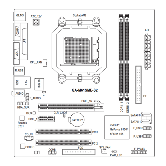
Page 7: Ga-M61Sme-S2 Motherboard Layout
GA-M61SME-S2 Motherboard Layout KB_MS Socket AM2 ATX_12V CPU_FAN R_USB GA-M61SME-S2 AUDIO F_AUDIO PCIE_16 HDA_SUR CLR_CMOS BIOS SATAII 0 PCIE_1 BATTERY SATAII 1 Realtek nVIDIA ® 8201 F_USB2 GeForce 6100/ PCI1 nForce 405 CD_IN F_USB1 PCI2 CODEC SYS_FAN F_PANEL COMB PWR_LED... -
Page 8: Block Diagram
Block Diagram PCIe CLK CPU CLK+/-(200 MHz) (100 MHz) DDRII 800/667/533/400 MHz DIMM Socket AM2 Dual Channel Memory Hyper Transport Bus PCI Express x8 PCI Express x1 Bus 2 SATA 3Gb/s PCIe CLK nVIDIA ® ATA-33/66/100/133 (100 MHz) GeForce 6100/ IDE Channel nForce 405 1 PCI Express x1... -
Page 9: Chapter 1 Hardware Installation
2. Damage as a result of violating the conditions recommended in the user manual. 3. Damage due to improper installation. 4. Damage due to use of uncertified components. 5. Damage due to use exceeding the permitted parameters. 6. Product determined to be an unofficial Gigabyte product. - 9 - Hardware Installation... -
Page 10: Feature Summary
1 front audio connector 1 CD In connector 1 S/PDIF In/Out connector 1 HDA_SUR connector 1 COMB connector 1 power LED connector 2 USB 2.0/1.1 connectors for additional 4 USB 2.0/1.1 ports by cables 1 Chassis Intrusion connector GA-M61SME-S2 Motherboard - 10 -... - Page 11 4 GB; Windows 64-bit operating system doesn't have such limitation. (Note 3) The GA-M61SME-S2 supports up to PCI Express x8 mode. (please refer to the VGA cards support list on page 16~17) (Note 4) Whether the CPU Smart FAN Control function is supported will depend on the CPU you install.
-
Page 12: Installation Of The Cpu And Cpu Cooler
Pin One Please use extra care when installing the CPU. The CPU will not fit if positioned incorrectly. Rather than applying force, please change the positioning of the CPU. GA-M61SME-S2 Motherboard - 12 -... -
Page 13: Installation Of The Cpu Cooler
1-3-2 Installation of the CPU Cooler Fig.1 Before installing the CPU cooler, please first add an even layer of heat paste on the surface of the CPU. Install all the CPU cooler components (Please refer to the cooler manual for detailed installation instructions). Fig.2 Please connect the CPU cooler power connector to the CPU_FAN connector located on the motherboard so that the CPU cooler can... -
Page 14: Installation Of Memory
DIMM socket. Then push it down. Fig.2 Close the plastic clip at both edges of the DIMM sockets to lock the DIMM module. Reverse the installation steps when you wish to remove the DIMM module. GA-M61SME-S2 Motherboard - 14 -... -
Page 15: Installation Of Expansion Cards
Dual Channel Memory Configuration The GA-M61SME-S2 supports the Dual Channel Technology. After operating the Dual Channel Technology, the bandwidth of Memory Bus will double. Due to CPU limitation, if you wish to operate the Dual Channel Technology, follow the guidelines below: 1. - Page 16 WinFast PX6600GT TDH ELSA GLADIAC 760GT ELSA GLADIAC 790GT Gigabyte GV-RX30S128D Gigabyte GV-RX30HM128D Gigabyte GV-RX30128D Gigabyte GV-RX60P128DE Gigabyte GV-RX60X128V Gigabyte GV-RX70128D Gigabyte GV-RX70P128D Gigabyte GV-RX80T256V Gigabyte GV-RX80L256V Gigabyte GV-RX80256D Gigabyte GV-RX55128D Gigabyte GV-RX85T256V-B Gigabyte GV-RC850T256D-B GA-M61SME-S2 Motherboard - 16 -...
-
Page 17: I/O Back Panel Introduction
Graphics Chip Maker Model Name Gigabyte GV-RX13P256D-RH Gigabyte GV-RX16P256DE-RH Gigabyte GV-RX18L256V-B Gigabyte GV-RX18T512V-B Gigabyte GV-RC19T512B-RH Gigabyte GV-RX165T256D-RH Gigabyte GV-RX13128D-RH Gigabyte GV-RX195P256D-RH Gigabyte GV-RX165P256D-RH Gigabyte GV-RX16T256V-RH ASUS AX800XT ASUS AX700PRO RX600 XT-TD128 GammaChrome S18 I/O Back Panel Introduction PS/2 Keyboard and PS/2 Mouse Connector To install a PS/2 port keyboard and mouse, plug the mouse to the upper port (green) and the keyboard to the lower port (purple). -
Page 18: Connectors Introduction
2. To set up an 8 channel audio configuration, you must use 5.1/7.1 Surround Cable (optional). Connectors Introduction ATX_12V F_AUDIO ATX (Power Connector) CD_IN CPU_FAN SPDIF_IO SYS_FAN HDA_SUR F_USB1 / F_USB2 COMB SATAII 0 / SATAII 1 PWR_LED CLR_CMOS F_PANEL BATTERY GA-M61SME-S2 Motherboard - 18 -... - Page 19 1/2) ATX_12V/ATX (Power Connector) With the use of the power connector, the power supply can supply enough stable power to all the components on the motherboard. Before connecting the power connector, please make sure that all components and devices are properly installed. Align the power connector with its proper location on the motherboard and connect tightly.
- Page 20 Slave (for information on settings, please refer to the instructions located on the IDE device). Before attaching the IDE cable, please take note of the foolproof groove in the IDE connector. GA-M61SME-S2 Motherboard - 20 -...
- Page 21 6) FDD (FDD Connector) This connector is used to connect a floppy disk drive. The types of floppy disk drives supported are: 360 KB, 720 KB, 1.2 MB, 1.44 MB, and 2.88 MB. Before connecting a floppy disk drive, be sure to locate pin 1 of the connector and the floppy disk drive cable.
-
Page 22: Front Panel Jumper
Pin 2- Pin 3: NC Pin 4: Data(-) RES (Reset Switch) Open: Normal Close: Reset Hardware System PW (Power Switch) Open: Normal Close: Power On/Off MSG (Message LED/Power/Sleep LED) Pin 1: LED anode(+) Pin 2: LED cathode(-) GA-M61SME-S2 Motherboard - 22 -... -
Page 23: Front Audio Connector
10) F_AUDIO (Front Audio Connector) This connector supports either HD (High Definition) or AC97 front panel audio module. If you wish to use the front audio function, connect the front panel audio module to this connector. Check the pin assignments carefully while you connect the front panel audio module. Incorrect connection between the module and connector will make the audio device unable to work or even damage it. - Page 24 S/PDIF cable, incorrect connection between the cable and connector will make the device unable to work or even damage it. For optional S/PDIF cable, please contact your local dealer. Pin No. Definition Power No Pin SPDIF SPDIFI GA-M61SME-S2 Motherboard - 24 -...
- Page 25 13) HDA_SUR (Surround Center Connector) Attach the connector of the 5.1/7.1 Surround Cable (optional) to this connector. Pin No. Definition LEF_P SURR_RR CEN_P SURR_LL CEN_JD SURR_JD -SUR_DET No Pin S_SURR_JD S_SURR_LL S_SURR_RR 14) F_USB1 / F_USB2 / (Front USB Connectors) Be careful with the polarity of the front USB connector.
- Page 26 No Pin 16) CI (Chassis Intrusion, Case Open) This 2-pin connector allows your system to detect if the chassis cover is removed. You can check the "Case Opened" status in BIOS Setup. Pin No. Definition Signal GA-M61SME-S2 Motherboard - 26 -...
-
Page 27: Hardware Installation
17) CLR_CMOS (Clear CMOS) You may clear the CMOS data to its default values by this header. To clear CMOS, temporarily short the two pins. Default doesn't include the jumper to avoid improper use of this header. Open: Normal Short: Clear CMOS 18) BATTERY Danger of explosion if battery is incorrectly replaced. - Page 28 GA-M61SME-S2 Motherboard - 28 -...
-
Page 29: Chapter 2 Bios Setup
CMOS SETUP screen. You can enter the BIOS setup screen by pressing "Ctrl + F1". If you wish to upgrade to a new BIOS, either Gigabyte's Q-Flash or @BIOS utility can be used. Q-Flash allows the user to quickly and easily update or backup BIOS without entering the operating system. -
Page 30: The Main Menu (For Example: Bios Ver. : E7)
<F12> : Boot Menu Select boot sequence for onboard (or add-on cards) device. Award Modular BIOS v6.00PG, An Energy Star Ally Copyright (C) 1984-2007, Award Software, Inc. GA-M61SME-S2 E7 <F12>:Boot Menu <DEL>:BIOS Setup/Q-Flash <F9>:Xpress Recovery2 <F12>:Boot Menu <End>:Qflash 01/23/2007-NV-MCP61-6A61KG05C-00 Use < > or < > to select a device, then press enter to accept . Press <ESC> to exit this menu. - Page 31 Standard CMOS Features This setup page includes all the items in standard compatible BIOS. Advanced BIOS Features This setup page includes all the items of Award special enhanced features. Integrated Peripherals This setup page includes all onboard peripherals. Power Management Setup This setup page includes all the items of Green function features.
-
Page 32: Standard Cmos Features
Allows BIOS to automatically detect IDE/SATA devices during POST(default) • None Select this if no IDE/SATA devices are used and the system will skip the automatic detection step and allow for faster system start up. GA-M61SME-S2 Motherboard - 32 -... - Page 33 Access Mode Use this to set the access mode for the hard drive. The two options are: Large/Auto(default: Auto) Capacity Capacity of currently installed hard disk. Hard drive information should be labeled on the outside drive casing. Enter the appropriate option based on this information.
-
Page 34: Advanced Bios Features
The system can not boot and can not access to Setup page will be denied if the correct password is not entered at the prompt. Setup The system will boot, but access to Setup will be denied if the correct password is not entered at the prompt. (Default value) GA-M61SME-S2 Motherboard - 34 -... - Page 35 HDD S.M.A.R.T. Capability This feature allows your hard disk to report read/write errors and to issue warnings when third- party hardware monitor utility is installed. Enabled Enable HDD S.M.A.R.T. capability. Disabled Disable HDD S.M.A.R.T. capability. (Default value) Away Mode Disabled Disable this function.
-
Page 36: Integrated Peripherals
NV SATA 1 Primary RAID Enabled Menu Level x NV SATA 1 Secondary RAID Enabled : Move Enter: Select +/-/PU/PD: Value F10: Save ESC: Exit F1: General Help F5: Previous Values F6: Fail-Safe Defaults F7: Optimized Defaults GA-M61SME-S2 Motherboard - 36 -... - Page 37 NV SATA RAID function Enabled Enable NV SATA RAID function. Disabled Disable NV SATA RAID function. (Default value) NV SATA 1 Primary RAID Enabled Enable NV SATA 1 primary RAID function. Disabled Disable this function. (Default value) NV SATA 1 Secondary RAID Enabled Enable NV SATA 1 secondary RAID function.
- Page 38 This option allows users to decide whether to detect USB storage devices, including USB flash drives and USB hard drives during POST. Enabled BIOS will scan all USB storage devices. (Default value) Disabled Disable this function. GA-M61SME-S2 Motherboard - 38 -...
-
Page 39: Power Management Setup
Power Management Setup CMOS Setup Utility-Copyright (C) 1984-2007 Award Software Power Management Setup ACPI Suspend Type [S1(POS)] Item Help Soft-Off by Power button [Instant-off] Menu Level PME Event Wake Up [Enabled] Modem Ring On [Enabled] USB Resume from Suspend [Enabled] Power-On by Alarm [Disabled] x Day of Month Alarm... - Page 40 When AC-power back to the system, the system will be in "Off" state. (Default value) Full-On When AC-power back to the system, the system always in "On" state. (Note) Supported on Vista operating system only. GA-M61SME-S2 Motherboard - 40 -...
-
Page 41: Pnp/Pci Configurations
PnP/PCI Configurations CMOS Setup Utility-Copyright (C) 1984-2007 Award Software PnP/PCI Configurations PCI 1 IRQ Assignment [Auto] Item Help PCI 2 IRQ Assignment [Auto] Menu Level : Move Enter: Select +/-/PU/PD: Value F10: Save ESC: Exit F1: General Help F5: Previous Values F6: Fail-Safe Defaults F7: Optimized Defaults PCI 1 IRQ Assignment... -
Page 42: Pc Health Status
Monitor system/CPU temperature at 90 C / 194 Disabled Disable this function. (Default value) CPU/SYSTEM FAN Fail Warning Disabled Disable the CPU/system fan fail warning function. (Default value) Enabled Enable the CPU/system fan fail warning function. GA-M61SME-S2 Motherboard - 42 -... - Page 43 CPU Smart FAN Control (Note) Disabled Disable this function. Enabled When this function is enabled, CPU fan will run at different speed depending on CPU temperature. Users can adjust the fan speed with Easy Tune based on their requirements. (Default value) CPU Smart FAN Mode This option is available only when CPU Smart FAN Control is enabled.
-
Page 44: Load Fail-Safe Defaults
PC Health Status ESC: Quit : Select Item F8: Q-Flash F10: Save & Exit Setup Load Optimized Defaults Selecting this field loads the factory defaults for BIOS and Chipset Features which the system automati- cally detects. GA-M61SME-S2 Motherboard - 44 -... -
Page 45: Set Supervisor/User Password
Set Supervisor/User Password CMOS Setup Utility-Copyright (C) 1984-2007 Award Software Standard CMOS Features Load Fail-Safe Defaults Load Optimized Defaults Advanced BIOS Features Set Supervisor Password Integrated Peripherals Set User Password Power Management Setup Enter Password: Save & Exit Setup PnP/PCI Configurations Exit Without Saving PC Health Status ESC: Quit... -
Page 46: Save & Exit Setup
PC Health Status ESC: Quit : Select Item F8: Q-Flash F10: Save & Exit Setup Abandon all Data Type "Y" will quit the Setup Utility without saving to RTC CMOS. Type "N" will return to Setup Utility. GA-M61SME-S2 Motherboard - 46 -... -
Page 47: Chapter 3 Drivers Installation
Chapter 3 Drivers Installation For Windows XP/2000 operating system, please install the NVIDIA GeForce 6100/nForce ® Series Utility CD. For Windows Vista operating system, please install the NVIDIA Series Vista Utility CD. ® Pictures below are shown in Windows XP. Insert the driver CD-title that came with your motherboard into your CD-ROM drive, the driver CD-title will auto start and show the installation guide. -
Page 48: Software Applications
Software Applications This page displays all the tools that Gigabyte developed and some free software, you can choose anyone you want and press "install" to install them. Driver CD Information This page lists the contents of software and drivers in this CD-title. -
Page 49: Hardware Information
Hardware Information This page lists all device you have for this motherboard. Contact Us Please see the last page for details. - 49 - Drivers Installation... - Page 50 GA-M61SME-S2 Motherboard - 50 -...
-
Page 51: Chapter 4 Appendix
Toggles between Easy and Advance Mode Display screen Display panel of CPU frequency Function display LEDs Shows the current functions status GIGABYTE Logo Log on to GIGABYTE website Help button Display EasyTune 5 Help file Exit or Minimize button Quit or Minimize EasyTune... -
Page 52: Xpress Recovery2 Introduction
Boot from CD/DVD: Press any key to startup XpressRecovery2..Award Modular BIOS v6.00PG, An Energy Star Ally Copyright (C) 1984-2007, Award Software, Inc. GA-M61SME-S2 E7 <F9>: Xpress Recovery2 <DEL>:BIOS Setup/Q-Flash <F9>:Xpress Recovery2 <F12>:Boot Menu <End>:Qflash 01/23/2007-NV-MCP61-6A61KG05C-00 1. If you have already entered Xpress Recovery2 by booting from the CD-ROM, you can enter Xpress Recovery2 by pressing the <F9>... - Page 53 The Main Screen of Xpress Recovery2 1. RESTORE: Restore the backed-up data to your hard disk. (This button will not appear if there is no backup file.) 2. BACKUP: Back up data from hard disk. 3. REMOVE: Remove previously-created backup files to release disk space.
-
Page 54: Updating The Bios
Before Use: Follow the steps below before using Q-Flash to update BIOS: 1. From GIGABYTE's website, download the latest compressed BIOS update file that matches your motherboard model. 2. Extract the file and save the new BIOS file (e.g. M61SMES2.F1) to your floppy disk, USB flash drive, or hard disk. - Page 55 c . Select the BIOS file and press ENTER. Make sure again the BIOS file matches your motherboard model. Step 2: The process of system reading the BIOS file from the floppy disk is displayed on the screen. When the message "Are you sure to update BIOS?" appears, press ENTER. The BIOS update will begin and the current process will be displayed.
- Page 56 BIOS. Fig 1. Installing the @BIOS utility Fig 2. Installation Complete and Run @BIOS Click Start/ Programs/ GIGABYTE/@BIOS Select @BIOS item than click Install Fig 3. The @BIOS Utility Fig 4. Select the desired @BIOS server Click "Update New BIOS"...
- Page 57 III. In method I, if the BIOS file you need cannot be found in @BIOS server, please go onto Gigabyte's web site for downloading and updating it according to method II. IV. Please note that any interruption during updating will cause system unbooted.
-
Page 58: Configuring Sata Hard Drive(S)
Attach one end of the SATA signal cable to the rear of the SATA hard drive and the other end to available SATA port(s) on the motherboard. Then connect the power connector from your power supply to the hard drive. (Note) Required for setting up RAID array. GA-M61SME-S2 Motherboard - 58 -... - Page 59 (2) Configuring SATA controller mode and boot sequence in BIOS Setup You have to make sure whether the SATA controller is configured correctly in system BIOS Setup and set BIOS boot sequence for the SATA hard drive(s)/RAID array. Step 1: Turn on your computer and press Del to enter BIOS Setup during POST (Power-On Self Test).
- Page 60 [Enable If No Ext PEG] : Move Enter: Select +/-/PU/PD: Value F10: Save ESC: Exit F1: General Help F5: Previous Values F6: Fail-Safe Defaults F7: Optimized Defaults Figure 3 Step 3: Save and exit BIOS Setup. GA-M61SME-S2 Motherboard - 60 -...
-
Page 61: Configuring Raid Set In Raid Bios
(3) Configuring RAID set in RAID BIOS Enter the RAID BIOS setup utility to configure a RAID array. Skip this step if you do not want to create RAID. Step 1: After the POST memory test begins and before the operating system boot begins, look for a message which says "Press F10 to enter RAID setup utility"... - Page 62 Clear disk data ? 1.0.M ST3120026AS 111.79GB [Y] YES [N] NO 1.1.M ST3120026AS 111.79GB [ ] Add [Y] YES [N] NO [ ] Del [ESC] Quit [F6] Back [F7] Finish [TAB] Navigate ] Select [ENTER] Popup Figure 7 GA-M61SME-S2 Motherboard - 62 -...
- Page 63 After that, the Array List screen displaying the RAID array you created will appear (Figure 8). (Note: BBS stands for BIOS Boot Specification. This indicates that the boot device is defined in the BIOS.) MediaShield Utility Aug 21 2006 - Array List - Boot Status Vendor...
- Page 64 Figure 11 (Note) For users without a startup disk: Use an alternative system and insert the GIGABYTE motherboard driver CD-ROM. From the CD-ROM drive folder, double click the MENU.exe file in the BootDrv folder (Figure 12). A command prompt window will open similar to that in Figure 11.
-
Page 65: Installing Sata Controller Driver During Os Installation
(5) Installing SATA controller driver during OS installation Now that you have prepared the SATA driver disk and configured BIOS settings, you are ready to install Windows 2000/XP onto your SATA hard drive with the SATA driver. The following is an example of Windows XP installation. - Page 66 S=Specify Additional Device Enter=Continue F3=Exit Figure 16 If a message appears saying one or some file(s) cannot be found, please check the floppy disk or copy the correct SATA driver again from the motherboard driver CD. GA-M61SME-S2 Motherboard - 66 -...
- Page 67 Step 4: When the next screen (Figure 17) appears, press ENTER to continue the SATA driver installation from the floppy disk. Windows Setup Setup will load support for the following mass storage device(s): NVIDIA RAID CLASS DRIVER (required) NVIDIA nForce Storage Controller (required) * To specify additional SCSI adapters, CD-ROM drives, or special disk controllers for use with Windows, including those for which you have a device support disk from a mass storage device...
-
Page 68: 4- / 6- / 8- Channel Audio Introduction
For the microphone to work correctly, you MUST connect it to either the default Mic In jack or the Line In jack and configure it in the audio driver. GA-M61SME-S2 Motherboard - 68 -... - Page 69 HD Audio With multiple built-in high quality digital-to-analog converters (DACs) that support audio output at up to 192 kHz/24-bit quality and multi-streaming applications, HD Audio is able to handle multiple audio streams (in and out) simultaneously. Multi-channel audio experiences have become a reality so you can, for instance, listen to MP3 music, have an Internet chat, make a telephone call over the Internet, and etc.
- Page 70 Choose a device depend- ing on the type of speaker connected (4-channel audio consists of Front Speaker Out (Line Out) and Rear Speaker Out) and then click OK. The 4- channel audio setup is completed. GA-M61SME-S2 Motherboard - 70 -...
- Page 71 Setting Up 6-Channel Audio STEP 1 : After installation of the audio driver, you should find an Audio Manager icon in your system tray (you can also find the icon in Control Panel). Double- click the icon to open the Audio Control Panel. STEP 2: In the Audio Control Panel, click the Audio I/O tab.
- Page 72 (8-channel audio consists of Front Speaker Out (Line Out), Rear Speaker Out, Center/Subwoofer Speaker Out, and Side Speaker Out) then click OK. The 8-chan- nel audio setup is completed. GA-M61SME-S2 Motherboard - 72 -...
- Page 73 Sound Effect Configuration: At the Sound Effect menu, users can adjust sound option settings as desired. AC'97 Audio Configuration: To enable the front panel audio connector to sup- port AC97 Audio mode, go to the Audio Control Panel and click the Audio I/O tab. In the ANA- LOG area, click the Tool icon and then select the Disable front panel jack detection check box.
-
Page 74: Troubleshooting
1 long, 2 short: Monitor or graphics card error 1 long, 3 short: Keyboard error 1 long, 9 short: BIOS ROM error Continuous long beeps: Graphics card not inserted properly Continuous short beeps: Power error GA-M61SME-S2 Motherboard - 74 -... -
Page 75: Troubleshooting Procedure
4-2-2 Troubleshooting Procedure If you encounter any troubles during system startup, follow the troubleshooting procedure below to solve the problem. START Turn off the power. Remove all peripherals, connecting cables, and power cord etc. Make sure the motherboard does not short-circuit with the chassis Isolate the short circuit. - Page 76 If the procedure above is unable to solve your problem, contact the place of purchase or local dealer for help. Or go to the Support\Technical Service Zone page to submit your question. Our customer service staff will reply you as soon as possible. GA-M61SME-S2 Motherboard - 76 -...
-
Page 77: Regulatory Statements
"end of life" product. Restriction of Hazardous Substances (RoHS) Directive Statement GIGABYTE products have not intended to add and safe from hazardous substances (Cd, Pb, Hg, Cr+6, PBDE and PBB). The parts and components have been carefully selected to meet RoHS requirement. - Page 78 "end of life" products, and generally improve our quality of life by ensuring that potentially hazardous substances are not released into the environment and are disposed of properly. China Restriction of Hazardous Substances Table The following table is supplied in compliance with China's Restriction of Hazardous Substances (China RoHS) requirements: GA-M61SME-S2 Motherboard - 78 -...
- Page 79 Contact Us Taiwan (Headquarters) China GIGA-BYTE TECHNOLOGY CO., LTD. NINGBO G.B.T. TECH. TRADING CO., LTD. Address: No.6, Bau Chiang Road, Hsin-Tien, WEB address : http://www.gigabyte.cn Taipei 231, Taiwan Shanghai TEL: +886-2-8912-4888 TEL: +86-21-63410999 FAX: +886-2-8912-4003 FAX: +86-21-63410100 Tech. and Non-Tech. Support (Sales/Marketing) : Beijing http://ggts.gigabyte.com.tw...
- Page 80 Czech Republic WEB address : http://www.gigabyte.co.yu Representative Office Of GIGA-BYTE Technology Co., Ltd. You may go to the GIGABYTE website, select your language in CZECH REPUBLIC in the language list on the top right corner of the website. WEB address : http://www.gigabyte.cz Turkey Representative Office Of GIGA-BYTE Technology Co., Ltd.
Need help?
Do you have a question about the GA-M61SME-S2 and is the answer not in the manual?
Questions and answers