Table of Contents
Advertisement
GA-M61P-S3
AMD Socket AM2 Processor Motherboard
User's Manual
Rev. 1002
12ME-M61PS3-1002R
* The WEEE marking on the product indicates this product must not be disposed of with user's other household waste
and must be handed over to a designated collection point for the recycling of waste electrical and electronic equipment!!
* The WEEE marking applies only in European Union's member states.
Advertisement
Table of Contents

Subscribe to Our Youtube Channel
Related Manuals for Gigabyte GA-M61P-S3


Summary of Contents for Gigabyte GA-M61P-S3
- Page 1 GA-M61P-S3 AMD Socket AM2 Processor Motherboard User's Manual Rev. 1002 12ME-M61PS3-1002R * The WEEE marking on the product indicates this product must not be disposed of with user's other household waste and must be handed over to a designated collection point for the recycling of waste electrical and electronic equipment!!
- Page 3 Gigabyte's prior written permission. Specifications and features are subject to change without prior notice. Product Manual Classification In order to assist in the use of this product, Gigabyte has categorized the user manual in the following: For quick installation, please refer to the "Hardware Installation Guide" included with the product.
-
Page 4: Table Of Contents
Table of Contents Item Checklist ......................... 6 Optional Accessories ...................... 6 GA-M61P-S3 Motherboard Layout ................7 Block Diagram ........................ 8 Chapter 1 Hardware Installation ..................9 Considerations Prior to Installation ..............9 Feature Summary ..................10 Installation of the CPU and CPU Cooler ............12 1-3-1 Installation of the CPU .................. - Page 5 Chapter 3 Drivers Installation ..................51 Install Chipset Drivers ..................51 Software Applications ..................52 Driver CD Information ..................52 Hardware Information ..................53 Contact Us ..................... 53 Chapter 4 Appendix ....................55 Unique Software Utilities ................55 4-1-1 EasyTune 5 Introduction ..................55 4-1-2 Xpress Recovery2 Introduction .................
-
Page 6: Item Checklist
Item Checklist IDE Cable x 1 & FDD Cable x 1 SATA 3Gb/s Cable x 2 I/O Shield * The items listed above are for reference only, and are subject to change without notice. Optional Accessories 2 Ports USB 2.0 Cable (Part Number: 12CR1-1UB030-51/R) 4 Ports USB 2.0 Cable (Part Number: 12CR1-1UB030-21/R) 2 Ports IEEE1394 Cable (Part Number: 12CF1-1IE008-01R) e-SATA Cable (Part Number: 12CF1-3SATPW-11R) -
Page 7: Ga-M61P-S3 Motherboard Layout
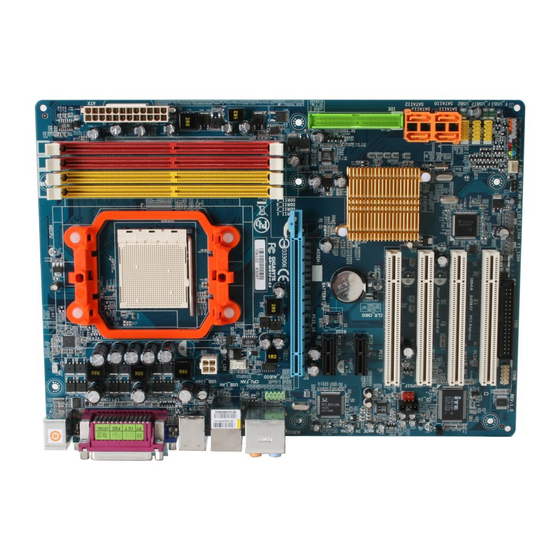
GA-M61P-S3 Motherboard Layout KB_MS Socket AM2 ATX_12V CPU_FAN AUDIO GA-M61P-S3 F_AUDIO Realtek 8211 PCIE_16 PCIE_1 BATTERY BIOS PCIE_2 nVIDIA ® CODEC CLR_CMOS GeForce 6100/ PCI1 nForce 430 CD_IN SPDIF_IO PCI2 SATAII3 SATAII2 SATAII1 SATAII0 PCI3 TSB43AB23 F_USB2 IT8716 F_USB1 PCI4... -
Page 8: Block Diagram
Block Diagram PCIe CLK CPU CLK+/-(200 MHz) (100 MHz) DDRII 800/667/533/400 MHz DIMM Socket AM2 Dual Channel Memory Hyper Transport Bus PCI Express x16 PCI Express x1 Bus 4 SATA 3Gb/s ATA 33/66/100/133 nVIDIA ® IDE Channel PCIe CLK GeForce 6100/ (100 MHz) nForce 430 BIOS... -
Page 9: Chapter 1 Hardware Installation
2. Damage as a result of violating the conditions recommended in the user manual. 3. Damage due to improper installation. 4. Damage due to use of uncertified components. 5. Damage due to use exceeding the permitted parameters. 6. Product determined to be an unofficial Gigabyte product. - 9 - Hardware Installation... -
Page 10: Feature Summary
1 S/PDIF In/Out connector 1 COMB connector 3 USB 2.0/1.1 connectors for additional 6 USB 2.0/1.1 ports by cables 2 IEEE 1394a connectors for additional 2 ports by cable 1 power LED connector 1 Chassis Intrusion connector GA-M61P-S3 Motherboard - 10 -... - Page 11 Rear Panel I/O 1 PS/2 keyboard port 1 PS/2 mouse port 1 parallel port 1 COMA port 1 VGA port 4 USB 2.0/1.1 ports 1 IEEE 1394a port 1 RJ-45 port 6 audio jacks (Line In / Line Out / MIC In/Surround Speaker Out (Rear Speaker Out)/Center/Subwoofer Speaker Out/Side Speaker Out) I/O Control IT8716 chip...
-
Page 12: Installation Of The Cpu And Cpu Cooler
Pin One Please use extra care when installing the CPU. The CPU will not fit if positioned incorrectly. Rather than applying force, please change the positioning of the CPU. GA-M61P-S3 Motherboard - 12 -... -
Page 13: Installation Of The Cpu Cooler
1-3-2 Installation of the CPU Cooler Fig.1 Before installing the CPU cooler, please first add an even layer of heat paste on the surface of the CPU. Install all the CPU cooler components (Please refer to the cooler manual for detailed installation instructions). Fig.2 Please connect the CPU cooler power connector to the CPU_FAN connector located on the motherboard so that the CPU cooler can... -
Page 14: Installation Of Memory
DIMM socket. Then push it down. Fig.2 Close the plastic clip at both edges of the DIMM sockets to lock the DIMM module. Reverse the installation steps when you wish to remove the DIMM module. GA-M61P-S3 Motherboard - 14 -... - Page 15 Dual Channel Memory Configuration The GA-M61P-S3 supports the Dual Channel Technology. After operating the Dual Channel Technology, the bandwidth of Memory Bus will double. Due to CPU limitation, if you wish to operate the Dual Channel Technology, follow the guidelines below: 1.
-
Page 16: Installation Of Expansion Cards
PCI Express x16 slot. When you try uninstall the VGA card, please press the latch as the picture to the left shows to release the card. GA-M61P-S3 Motherboard - 16 -... -
Page 17: I/O Back Panel Introduction
I/O Back Panel Introduction PS/2 Keyboard and PS/2 Mouse Connector To install a PS/2 port keyboard and mouse, plug the mouse to the upper port (green) and the keyboard to the lower port (purple). Parallel Port The parallel port allows connection of a printer, scanner and other peripheral devices. COMA Connects to serial-based mouse or data processing devices. -
Page 18: Connectors Introduction
Connectors Introduction ATX_12V F_AUDIO ATX (Power Connector) CD_IN CPU_FAN SPDIF_IO SYS_FAN F_USB1 / F_USB2 / F_USB3 F1_1394 / F2_1394 COMB SATAII0 / 1 / 2 / 3 PWR_LED CLR_CMOS F_PANEL BATTERY GA-M61P-S3 Motherboard - 18 -... - Page 19 1/2) ATX_12V/ATX (Power Connector) With the use of the power connector, the power supply can supply enough stable power to all the components on the motherboard. Before connecting the power connector, please make sure that all components and devices are properly installed. Align the power connector with its proper location on the motherboard and connect tightly.
- Page 20 IDE devices, please set the jumper on one IDE device as Master and the other as Slave (for information on settings, please refer to the instructions located on the IDE device). Before attaching the IDE cable, please take note of the foolproof groove in the IDE connector. GA-M61P-S3 Motherboard - 20 -...
- Page 21 6) FDD (FDD Connector) The FDD connector is used to connect the FDD cable while the other end of the cable connects to the FDD drive. The types of FDD drives supported are: 360 KB, 720 KB, 1.2 MB, 1.44 MB and 2.88 MB.
-
Page 22: Front Panel Jumper
RES (Reset Switch) Open: Normal (Green) Close: Reset Hardware System PW (Power Switch) Open: Normal (Red) Close: Power On/Off MSG (Message LED/Power/Sleep LED) Pin 1: LED anode(+) (Yellow) Pin 2: LED cathode(-) NC ( Purple) GA-M61P-S3 Motherboard - 22 -... -
Page 23: Front Audio Connector
10) F_AUDIO (Front Audio Connector) This connector supports either HD (High Definition) or AC97 front panel audio module. If you wish to use the front audio function, connect the front panel audio module to this connector. Check the pin assignments carefully while you connect the front panel audio module. Incorrect connection between the module and connector will make the audio device unable to work or even damage it. - Page 24 S/PDIF cable, incorrect connection between the cable and connector will make the device unable to work or even damage it. For optional S/PDIF cable, please contact your local dealer. Pin No. Definition Power No Pin SPDIF SPDIFI GA-M61P-S3 Motherboard - 24 -...
- Page 25 13) F_USB1 / F_USB2 / F_USB3 (Front USB Connectors) Be careful with the polarity of the front USB connector. Check the pin assignment carefully while you connect the front USB cable, incorrect connection between the cable and connector will make the device unable to work or even damage it.
- Page 26 No Pin 16) CI (Chassis Intrusion, Case Open) This 2-pin connector allows your system to detect if the chassis cover is removed. You can check the "Case Opened" status in BIOS Setup. Pin No. Definition Signal GA-M61P-S3 Motherboard - 26 -...
- Page 27 17) CLR_CMOS (Clear CMOS) You may clear the CMOS data to its default values by this header. To clear CMOS, temporarily short the two pins. Default doesn't include the jumper to avoid improper use of this header. Open: Normal Short: Clear CMOS 18) BATTERY Danger of explosion if battery is incorrectly replaced.
- Page 28 GA-M61P-S3 Motherboard - 28 -...
-
Page 29: Chapter 2 Bios Setup
CMOS SETUP screen. You can enter the BIOS setup screen by pressing "Ctrl + F1". If you wish to upgrade to a new BIOS, either Gigabyte's Q-Flash or @BIOS utility can be used. Q-Flash allows the user to quickly and easily update or backup BIOS without entering the operating system. -
Page 30: The Main Menu (For Example: Bios Ver. : D8)
This action makes the system reset to the default settings for stability. 3. The BIOS Setup menus described in this chapter are for reference only and may differ from the exact settings for your motherboard. GA-M61P-S3 Motherboard - 30 -... - Page 31 Standard CMOS Features This setup page includes all the items in standard compatible BIOS. Advanced BIOS Features This setup page includes all the items of Award special enhanced features. Integrated Peripherals This setup page includes all onboard peripherals. Power Management Setup This setup page includes all the items of Green function features.
-
Page 32: Standard Cmos Features
Press "Enter" to select this option for automatic device detection. Extended IDE Drive. IDE/SATA Device Setup. You can use one of the two methods: • Auto Allows BIOS to automatically detect IDE/SATA devices during POST. (default) GA-M61P-S3 Motherboard - 32 -... - Page 33 • None Select this if no IDE/SATA devices are used and the system will skip the automatic detection step and allow for faster system start up. Access Mode Use this to set the access mode for the hard drive. The two options are: Large/Auto(default:Auto) Capacity Capacity of currently installed hard drive.
-
Page 34: Advanced Bios Features
The system can not boot and can not access to Setup page will be denied if the correct password is not entered at the prompt. Setup The system will boot, but access to Setup will be denied if the correct password is not entered at the prompt. (Default value) GA-M61P-S3 Motherboard - 34 -... - Page 35 HDD S.M.A.R.T. Capability This feature allows your hard disk to report read/write errors and to issue warnings when third- party hardware monitor utility is installed. Enabled Enable HDD S.M.A.R.T. capability. Disabled Disable HDD S.M.A.R.T. capability. (Default value) Away Mode Disabled Disable this function.
-
Page 36: Integrated Peripherals
Enable RAID function for the first channel of the first SATA 3Gb/s controller. (Default value) Disabled Disable this function. NV SATA 1 Secondary RAID Enabled Enable RAID function for the second channel of the first SATA 3Gb/s controller. (Default value) Disabled Disable this function. GA-M61P-S3 Motherboard - 36 -... - Page 37 NV SATA 2 Primary RAID Enabled Enable RAID function for the first channel of the second SATA 3Gb/s controller. (Default value) Disabled Disable this function. NV SATA 2 Secondary RAID Enabled Enable RAID function for the second channel of the second SATA 3Gb/s controller. (Default value) Disabled Disable this function.
- Page 38 Explanation: A fault or short might occur at about 1.6m on Pair 1-2. Note: Pair 4-5 and Pair 7-8 are not used in a 10/100 Mbps environment, their Status fields will show Open, and the length shown is the approximate length of the attached LAN cable. GA-M61P-S3 Motherboard - 38 -...
- Page 39 OnBoard LAN Boot ROM This function decide whether to invoke the boot ROM of the onboard LAN chip. Enabled Enable this function. Disabled Disable this function. (Default value) Onboard Serial Port 1 Auto BIOS will automatically setup the port 1 address. 3F8/IRQ4 Enable onboard Serial Port 1 and address is 3F8/IRQ4.
-
Page 40: Power Management Setup
Enable PME as wake up event. (Default value) Modem Ring On An incoming call via modem can awake the system from any suspend state. Disabled Disable this function. Enabled Enable Modem Ring On function. (Default value) GA-M61P-S3 Motherboard - 40 -... - Page 41 USB Resume from Suspend Disabled Disable this function. Enabled Enable USB device wake up system from suspend mode. (Default value) Power-On by Alarm You can enable the "Power-On by Alarm" item and key in Date/Time to power on system. Disabled Disable this function.
-
Page 42: Pnp/Pci Configurations
Auto assign IRQ to PCI 3. (Default value) 3,4,5,7,9,10,11,12,14,15 Set IRQ 3,4,5,7,9,10,11,12,14,15 to PCI 3. PCI 4 IRQ Assignment Auto Auto assign IRQ to PCI 4. (Default value) 3,4,5,7,9,10,11,12,14,15 Set IRQ 3,4,5,7,9,10,11,12,14,15 to PCI 4. GA-M61P-S3 Motherboard - 42 -... -
Page 43: Pc Health Status
PC Health Status CMOS Setup Utility-Copyright (C) 1984-2006 Award Software PC Health Status Reset Case Open Status [Disabled] Item Help Case Opened Menu Level Vcore DDR2 18V +3.3V +12V Current System Temperature Current CPU Temperature Current CPU FAN Speed 3245 RPM Current SYSTEM FAN Speed 0 RPM System Warning Temperature... - Page 44 When this function is enabled, system fan will run at different speed depend- ing on system temperature. Users can adjust the fan speed with Easy Tune based on their requirements. (Note) Whether the CPU Smart FAN Control function is supported will depend on the CPU you install. GA-M61P-S3 Motherboard - 44 -...
-
Page 45: Mb Intelligent Tweaker(M.i.t.)
MB Intelligent Tweaker(M.I.T.) CMOS Setup Utility-Copyright (C) 1984-2006 Award Software MB Intelligent Tweaker(M.I.T.) CPU Frequency (MHz) [200] Item Help PCIE Clock (MHz) [100] Menu Level CPU Clock Ratio [Auto] Robust Graphics Booster [Disabled] x VGA Core Clock CPU HT-Link Voltage [Normal] Chipset Voltage Control [Normal]... - Page 46 Please note that by overclocking your system through the increase of the CPU voltage, damage to the CPU or decrease in the CPU life expectancy may occur. Supports adjustable CPU voltage from 0.8000V to 1.5500V. (Default value: Normal) Normal CPU Vcore Displays your CPU's normal vcore voltage. GA-M61P-S3 Motherboard - 46 -...
-
Page 47: Load Fail-Safe Defaults
Load Fail-Safe Defaults CMOS Setup Utility-Copyright (C) 1984-2006 Award Software Standard CMOS Features Load Fail-Safe Defaults Advanced BIOS Features Load Optimized Defaults Integrated Peripherals Set Supervisor Password Power Management Setup Set User Password Load Fail-Safe Defaults (Y/N)? N PnP/PCI Configurations Save &... -
Page 48: Set Supervisor/User Password
Setup Menu. If you select "Setup" at "Password Check" in Advance BIOS Features Menu, you will be prompted only when you try to enter Setup. GA-M61P-S3 Motherboard - 48 -... -
Page 49: Save & Exit Setup
2-11 Save & Exit Setup CMOS Setup Utility-Copyright (C) 1984-2006 Award Software Standard CMOS Features Load Fail-Safe Defaults Advanced BIOS Features Load Optimized Defaults Integrated Peripherals Set Supervisor Password Save to CMOS and EXIT (Y/N)? Y Power Management Setup Set User Password PnP/PCI Configurations Save &... - Page 50 GA-M61P-S3 Motherboard - 50 -...
-
Page 51: Chapter 3 Drivers Installation
Chapter 3 Drivers Installation Pictures below are shown in Windows XP. Insert the driver CD-title that came with your motherboard into your CD-ROM drive, the driver CD-title will auto start and show the installation guide. If not, please double click the CD-ROM device icon in "My computer", and execute the Run.exe. -
Page 52: Software Applications
Software Applications This page displays all the tools that Gigabyte developed and some free software, you can choose anyone you want and press "install" to install them. Driver CD Information This page lists the contents of software and drivers in this CD-title. -
Page 53: Hardware Information
Hardware Information This page lists all device you have for this motherboard. Contact Us Please see the last page for details. - 53 - Drivers Installation... - Page 54 GA-M61P-S3 Motherboard - 54 -...
-
Page 55: Chapter 4 Appendix
Toggles between Easy and Advance Mode Display screen Display panel of CPU frequency Function display LEDs Shows the current functions status GIGABYTE Logo Log on to GIGABYTE website Help button Display EasyTune 5 Help file Exit or Minimize button Quit or Minimize EasyTune... -
Page 56: Xpress Recovery2 Introduction
2. System storage capacity and the reading/writing speed of the hard disk will affect the data backup speed. 3. It is recommended that Xpress Recovery2 be immediately installed once you com- plete installations of OS and all required drivers as well as software. GA-M61P-S3 Motherboard - 56 -... - Page 57 The Main Screen of Xpress Recovery2 1. RESTORE: Restore the backed-up data to your hard disk. (This button will not appear if there is no backup file.) 2. BACKUP: Back up data from hard disk. 3. REMOVE: Remove previously-created backup files to release disk space.
-
Page 58: Flash Bios Method Introduction
Before Use: Follow the steps below before using Q-Flash to update BIOS: 1. From GIGABYTE's website, download the latest compressed BIOS update file that matches your motherboard model 2. Extract the downloaded BIOS files and save the new BIOS file (e.g. M61PMS2.F1) to your floppy disk or hard disk. - Page 59 Step 2: The process of system reading the BIOS file from the floppy disk is displayed on the screen. When the message "Are you sure to update BIOS?" appears, press ENTER. The BIOS update will begin and the current process will be displayed. 1.
- Page 60 Windows. Just select the desired @BIOS server to download the latest version of BIOS. Fig 1. Installing the @BIOS utility Fig 2. Installation Complete and Run @BIOS Click Start/ Programs/ GIGABYTE/@BIOS Select @BIOS item than click Install Fig 3. The @BIOS Utility Fig 4. Select the desired @BIOS server Click "Update New BIOS"...
- Page 61 III. In method I, if the BIOS file you need cannot be found in @BIOS server, please go onto Gigabyte's web site for downloading and updating it according to method II. IV. Please note that any interruption during updating will cause system unbooted.
-
Page 62: Configuring Sata Hard Drive(S)
Attach one end of the SATA signal cable to the rear of the SATA hard drive and the other end to available SATA port(s) on the motherboard. Then connect the power connector from your power supply to the hard drive. (Note) Required for setting up RAID array. GA-M61P-S3 Motherboard - 62 -... - Page 63 (2) Configuring SATA controller mode and boot sequence in BIOS Setup Make sure to configure the SATA controller mode correctly in system BIOS Setup and set the first boot device. Step 1: Turn on your computer and press Del to enter BIOS Setup during POST (Power-On Self Test). In BIOS Setup, go to Integrated Periperals -->...
- Page 64 [Enable If No Ext PEG] : Move Enter: Select +/-/PU/PD: Value F10: Save ESC: Exit F1: General Help F5: Previous Values F6: Fail-Safe Defaults F7: Optimized Defaults Figure 3 Step 3: Save and exit BIOS Setup. GA-M61P-S3 Motherboard - 64 -...
- Page 65 (3) Configuring RAID set in RAID BIOS Enter the RAID BIOS setup utility to configure a RAID array. Skip this step if you do not want to create RAID. Step 1: After the POST memory test begins and before the operating system boot begins, look for a message which says "Press F10 to enter RAID setup utility"...
- Page 66 Clear disk data ? 1.0.M ST3120026AS 111.79GB [Y] YES [N] NO [ ] Add 1.1.M ST3120026AS 111.79GB [Y] YES [N] NO [ ] Del [ESC] Quit [F6] Back [F7] Finish [TAB] Navigate ] Select [ENTER] Popup Figure 7 GA-M61P-S3 Motherboard - 66 -...
- Page 67 After that, the Array List screen displaying the RAID array you created will appear (Figure 8). (Note: BBS stands for BIOS Boot Specification. This indicates that the boot device is defined in the BIOS.) MediaShield Utility Aug 21 2006 - Array List - Boot Status Vendor...
- Page 68 Press 0 to exit when finished. (Note) For users without a startup disk: Use an alternative system and insert the GIGABYTE motherboard driver CD-ROM. From the CD-ROM drive folder, double click the MENU.exe file in the BootDrv folder (Figure 12). A command prompt window will open similar to that in Figure 11.
-
Page 69: Installing Sata Controller Driver During Os Installation
(5) Installing SATA controller driver during OS installation Now that you have prepared the SATA driver disk and configured BIOS settings, you are ready to install Windows 2000/XP onto your SATA hard drive with the SATA driver. The following is an example of Windows XP installation. - Page 70 S=Specify Additional Device Enter=Continue F3=Exit Figure 16 If a message appears saying one or some file(s) cannot be found, please check the floppy disk or copy the correct SATA driver again from the motherboard driver CD. GA-M61P-S3 Motherboard - 70 -...
- Page 71 Step 4: When the next screen (Figure 17) appears, press ENTER to continue the SATA driver installation from the floppy disk. Windows Setup Setup will load support for the following mass storage device(s): NVIDIA RAID CLASS DRIVER (required) NVIDIA nForce Storage Controller (required) * To specify additional SCSI adapters, CD-ROM drives, or special disk controllers for use with Windows, including those for which you have a device support disk from a mass storage device...
-
Page 72: 4- / 6- / 8- Channel Audio Function Introduction
After installation of the audio driver, you should find an Audio Manager icon in your system tray (you can also find the icon in Control Panel). Double- click the icon to open the Audio Control Panel. GA-M61P-S3 Motherboard - 72 -... - Page 73 STEP 2: In the Audio Control Panel, click the Audio I/O tab. In the upper left list, click 2CH Speaker. STEP 3: After a speaker or headphone is plugged into the rear Line Out jack, a small window will pop up and ask you what type of equipment is connected.
- Page 74 Choose a device depending on the type of speaker connected (6-channel audio consists of Front Speaker Out (Line Out), Rear Speaker Out, and Center/Subwoofer Speaker Out) then click OK. The 6-channel audio setup is completed. GA-M61P-S3 Motherboard - 74 -...
- Page 75 8 Channel Audio Setup STEP 1 : After installation of the audio driver, you should find an Audio Manager icon in your system tray (you can also find the icon in Control Panel). Double- click the icon to open the Audio Control Panel. STEP 2: In the Audio Control Panel, click the Audio I/O tab.
- Page 76 AC97 Audio mode, go to the Audio Control Panel and click the Audio I/O tab. In the ANA- LOG area, click the Tool icon and then select the Disable front panel jack detection check box. This action completes the AC'97 Audio configuration. GA-M61P-S3 Motherboard - 76 -...
-
Page 77: Troubleshooting
Below is a collection of general asked questions. To check general asked questions based on a specific motherboard model, please log on to http://www.gigabyte.com.tw Question 1: I cannot see some options that were included in previous BIOS after updating BIOS. Why? Answer: Some advanced options are hidden in new BIOS version. - Page 78 Contact Us Taiwan (Headquarters) China GIGA-BYTE TECHNOLOGY CO., LTD. NINGBO G.B.T. TECH. TRADING CO., LTD. Address: No.6, Bau Chiang Road, Hsin-Tien, WEB address : http://www.gigabyte.cn Taipei 231, Taiwan Shanghai TEL: +886-2-8912-4888 TEL: +86-21-63410999 FAX: +886-2-8912-4003 FAX: +86-21-63410100 Tech. and Non-Tech. Support (Sales/Marketing) : Beijing http://ggts.gigabyte.com.tw...
- Page 79 Germany Russia G.B.T. TECHNOLOGY TRADING GMBH Moscow Representative Office Of GIGA-BYTE Technology WEB address : http://www.gigabyte.de Co., Ltd. U.K. WEB address : http://www.gigabyte.ru G.B.T. TECH. CO., LTD. Latvia WEB address : http://www.giga-byte.co.uk GIGA-BYTE Latvia The Netherlands WEB address : http://www.gigabyte.com.lv GIGA-BYTE TECHNOLOGY B.V.
- Page 80 - 80 -...
Need help?
Do you have a question about the GA-M61P-S3 and is the answer not in the manual?
Questions and answers