
Related Manuals for Gigabyte GA-M61SME-S2L


Summary of Contents for Gigabyte GA-M61SME-S2L
- Page 1 GA-M61SME-S2L AM2 socket motherboard for AMD Athlon 64 FX processor/ AMD Athlon 64 X2 Dual-Core processor/ AMD Athlon 64 processor/AMD Sempron processor User's Manual Rev. 2003 12ME-M61SMES2L-2003R...
-
Page 3: Identifying Your Motherboard Revision
GIGABYTE's prior written permission. Documentation Classifications In order to assist in the use of this product, GIGABYTE provides the following types of documentations: For detailed product information, carefully read the User's Manual. For instructions on how to use GIGABYTE's unique features, read or download the information on/from the Support\Motherboard\Technology Guide page on our website. -
Page 4: Table Of Contents
Table of Contents Optional Items ......................... 6 Box Contents ......................... 6 GA-M61SME-S2L Motherboard Layout ................. 7 Block Diagram ........................ 8 Chapter 1 Hardware Installation ..................9 Installation Precautions ..................9 Product Specifications ..................10 Installing the CPU and CPU Cooler .............. 12 1-3-1 Installing the CPU .................... - Page 5 Chapter 3 Drivers Installation ..................51 Installing Chipset Drivers ................51 Software Applications ..................52 Driver CD Information ..................52 Hardware Information ..................53 Contact Us ..................... 53 Chapter 4 Unique Features ..................55 Xpress Recovery2 ..................55 BIOS Update Utilities ..................60 4-2-1 Updating the BIOS with the Q-Flash Utility ............
-
Page 6: Optional Items
Box Contents GA-M61SME-S2L motherboard Motherboard driver disk User's Manual One IDE cable One SATA 3Gb/s cable I/O Shield The box contents above are for reference only and the actual items shall depend on product package you obtain. The box contents are subject to change without notice. -
Page 7: Ga-M61Sme-S2L Motherboard Layout
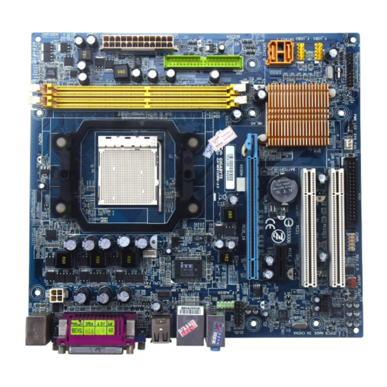
GA-M61SME-S2L Motherboard Layout KB_MS Socket AM2 ATX_12V CPU_FAN R_USB GA-M61SME-S2L AUDIO F_AUDIO PCIE_16 CLR_CMOS BIOS SATAII 0 PCIE_1 BATTERY SATAII 1 Realtek nVIDIA ® 8201CL F_USB2 GeForce 6100/ PCI1 nForce 405 CD_IN F_USB1 PCI2 CODEC SYS_FAN F_PANEL SPDIF_IO PWR_LED - 7 -... -
Page 8: Block Diagram
Block Diagram PCIe CLK CPU CLK+/-(200 MHz) (100 MHz) DDR2 800/667/533 MHz DIMM Socket AM2 Dual Channel Memory Hyper Transport Bus PCI Express x8 D-Sub PCI Express x1 Bus 8 USB Ports nVIDIA ® PCIe CLK GeForce 6100/ (100 MHz) nForce 405 2 SATA 3Gb/s 1 PCI Express x1... -
Page 9: Chapter 1 Hardware Installation
Chapter 1 Hardware Installation Installation Precautions The motherboard contains numerous delicate electronic circuits and components which can become damaged as a result of electrostatic discharge (ESD). Prior to installation, carefully read the user's manual and follow these procedures: Prior to installation, do not remove or break motherboard S/N (Serial Number) sticker or •... -
Page 10: Product Specifications
Support for Socket AM2 processors: AMD Athlon 64 FX processor/AMD Athlon 64 X2 Dual-Core processor/ AMD Athlon 64 processor/AMD Sempron processor (Go to GIGABYTE's website for the latest CPU support list.) Front Side Bus 2000 MHz FSB Chipset nVIDIA GeForce 6100/nForce 405 chipset ®... - Page 11 (Note 1) Due to Windows XP 32-bit operating system limitation, when more than 4 GB of physical memory is installed, the actual memory size displayed will be less than 4 GB. (Note 2) The GA-M61SME-S2L supports up to PCI Express x8 mode. (Please refer to the graphics cards support list on page 18) (Note 3) Whether the CPU fan speed control function is supported will depend on the CPU you install.
-
Page 12: Installing The Cpu And Cpu Cooler
Read the following guidelines before you begin to install the CPU: • Make sure that the motherboard supports the CPU. (Go to GIGABYTE's website for the latest CPU support list.) • Always turn off the computer and unplug the power cord from the power outlet before installing the CPU to prevent hardware damage. - Page 13 B. Follow the steps below to correctly install the CPU into the motherboard CPU socket. Before installing the CPU, make sure to turn off the computer and unplug the power cord from the power outlet to prevent damage to the CPU. CPU Socket Locking Lever Step 1:...
-
Page 14: Installing The Cpu Cooler
1-3-2 Installing the CPU Cooler Follow the steps below to correctly install the CPU cooler on the CPU. (The following procedure uses the GIGABYTE cooler as the example.) Step 1: Step 2: Apply an even and thin layer of thermal grease Place the CPU cooler on the CPU. -
Page 15: Installing The Memory
• Make sure that the motherboard supports the memory. It is recommended that memory of the same capacity, brand, speed, and chips be used. (Go to GIGABYTE's website for the latest memory support list.) • Always turn off the computer and unplug the power cord from the power outlet before installing the memory to prevent hardware damage. -
Page 16: Installing A Memory
Step 2: The clips at both ends of the socket will snap into place when the memory module is securely inserted. GA-M61SME-S2L Motherboard - 16 -... -
Page 17: Installing An Expansion Card
Installing an Expansion Card Read the following guidelines before you begin to install an expansion card: • Make sure the motherboard supports the expansion card. Carefully read the manual that came with your expansion card. • Always turn off the computer and unplug the power cord from the power outlet before installing an expansion card to prevent hardware damage. - Page 18 GV-NX76G256D-RH Gigabyte GV-NX73T256D-RH Gigabyte GV-NX73G128D-RH Gigabyte GV-NX73L128D-RH Gigabyte GV-NX65128DE Gigabyte GV-NX79G256DP-RH Gigabyte GV-NX71G512P8-RH Nvidia 7900GTX Nvidia 8800GTX Nvidia P502/P602 ASUS EN6600GT/TD/128 ASUS EN6600/TD/128 NX6800GT-TD256E Leadtek WinFast PX6600GT TDH ELSA GLADIAC 760GT ELSA GLADIAC 790GT (Continued...) GA-M61SME-S2L Motherboard - 18 -...
- Page 19 Graphics Chip Maker Model Name Gigabyte GV-RX30S128D Gigabyte GV-RX30HM128D Gigabyte GV-RX30128D Gigabyte GV-RX60P128DE Gigabyte GV-RX60X128V Gigabyte GV-RX70128D Gigabyte GV-RX70P128D Gigabyte GV-RX80T256V Gigabyte GV-RX80L256V Gigabyte GV-RX80256D Gigabyte GV-RX55128D Gigabyte GV-RX85T256V-B Gigabyte GV-RC850T256D-B Gigabyte GV-RX13P256D-RH Gigabyte GV-RX16P256DE-RH Gigabyte GV-RX18L256V-B Gigabyte GV-RX18T512V-B Gigabyte...
-
Page 20: Back Panel Connectors
• When removing the cable, pull it straight out from the connector. Do not rock it side to side to prevent an electrical short inside the cable connector. GA-M61SME-S2L Motherboard - 20 -... - Page 21 Line In Jack (Blue) The default line in jack. Use this audio jack for line in devices such as an optical drive, walkman, etc. Line Out Jack (Front Speaker Out, Green) The default line out jack. Use this audio jack for a headphone or 2-channel speaker. This jack can be used to connect front speakers in a 4/5.1-channel audio configuration.
-
Page 22: Internal Connectors
• After installing the device and before turning on the computer, make sure the device cable has been securely attached to the connector on the motherboard. GA-M61SME-S2L Motherboard - 22 -... - Page 23 1/2) ATX_12V/ATX (2x2 12V Power Connector and 2x12 Main Power Connector) With the use of the power connector, the power supply can supply enough stable power to all the components on the motherboard. Before connecting the power connector, first make sure the power supply is turned off and all devices are properly installed.
- Page 24 360 KB, 720 KB, 1.2 MB, 1.44 MB, and 2.88 MB. Before connecting a floppy disk drive, be sure to locate pin 1 of the connector and the floppy disk drive cable. The pin 1 of the cable is typically designated by a stripe of different color. GA-M61SME-S2L Motherboard - 24 -...
- Page 25 6) IDE (IDE Connector) The IDE connector supports up to two IDE devices such as hard drives and optical drives. Before attaching the IDE cable, locate the foolproof groove on the connector. If you wish to connect two IDE devices, remember to set the jumpers and the cabling according to the role of the IDE devices (for example, master or slave).
-
Page 26: System Power Led Header
• When installing the battery, note the orientation of the positive side (+) and the negative side (-) of the battery (the positive side should face up). • Used batteries must be handled in accordance with local environmental regulations. GA-M61SME-S2L Motherboard - 26 -... - Page 27 10) F_PANEL (Front Panel Header) Connect the power switch, reset switch, speaker and system status indicator on the chassis front panel to this header according to the pin assignments below. Note the positive and negative pins before connecting the cables. Message/Power/ Power Speaker...
-
Page 28: Cd In Connector
12) CD_IN (CD In Connector) You may connect the audio cable that came with your optical drive to the header. Pin No. Definition CD-L CD-R GA-M61SME-S2L Motherboard - 28 -... -
Page 29: Usb Headers
13) SPDIF_IO (S/PDIF Out Header) This header supports digital S/PDIF out. Via an optional S/PDIF out cable, this header can connect to an audio device that supports digital audio in. For purchasing the optional S/PDIF out cable, please contact the local dealer. Pin No. -
Page 30: Clearing Cmos Jumper
Failure to do so may cause damage to the motherboard. • After system restart, go to BIOS Setup to load factory defaults (select Load Optimized Defaults) or manually configure the BIOS settings (refer to Chapter 2, "BIOS Setup," for BIOS configurations). GA-M61SME-S2L Motherboard - 30 -... -
Page 31: Chapter 2 Bios Setup
To see more advanced BIOS Setup menu options, you can press <Ctrl> + <F1> in the main menu of the BIOS Setup program. To upgrade the BIOS, use either the GIGABYTE Q-Flash or @BIOS utility. Q-Flash allows the user to quickly and easily upgrade or back up BIOS without entering the •... -
Page 32: Startup Screen
BIOS Setup settings. You can access Boot Menu again to change the first boot device setting as needed. <End>: Q-Flash Press the <End> key to access the Q-Flash utility directly without having to enter BIOS Setup first. GA-M61SME-S2L Motherboard - 32 -... -
Page 33: The Main Menu
The Main Menu Once you enter the BIOS Setup program, the Main Menu (as shown below) appears on the screen. Use arrow keys to move among the items and press <Enter> to accept or enter a sub-menu. (Sample BIOS Version: E2) CMOS Setup Utility-Copyright (C) 1984-2007 Award Software Standard CMOS Features Load Fail-Safe Defaults... - Page 34 (Pressing <F10> can also carry out this task.) Exit Without Saving Abandon all changes and the previous settings remain in effect. Pressing <Y> to the confirmation message will exit BIOS Setup. (Pressing <Esc> can also carry out this task.) GA-M61SME-S2L Motherboard - 34 -...
-
Page 35: Standard Cmos Features
Standard CMOS Features CMOS Setup Utility-Copyright (C) 1984-2007 Award Software Standard CMOS Features Date (mm:dd:yy) Fri, Jul 20 2007 Item Help Time (hh:mm:ss) 11:52:24 Menu Level IDE Channel 0 Master [None] IDE Channel 0 Slave [None] IDE Channel 2 Master [None] IDE Channel 3 Master [None]... - Page 36 These fields are read-only and are determined by the BIOS POST. Base Memory Also called conventional memory. Typically, 640 KB will be reserved for the MS-DOS operating system. Extended Memory The amount of extended memory. GA-M61SME-S2L Motherboard - 36 -...
-
Page 37: Advanced Bios Features
Advanced BIOS Features CMOS Setup Utility-Copyright (C) 1984-2007 Award Software Advanced BIOS Features AMD K8 Cool&Quiet control [Auto] Item Help Hard Disk Boot Priority [Press Enter] Menu Level First Boot Device [Floppy] Second Boot Device [Hard Disk] Third Boot Device [CDROM] Password Check [Setup]... - Page 38 Activates the onboard VGA only if no PCI Express VGA card is installed. (Default) Always Enable Always activates the onboard VGA, whether or not a PCI Express card is installed. If you wish to set up a dual view configuration, set this item to Always Enable. GA-M61SME-S2L Motherboard - 38 -...
-
Page 39: Integrated Peripherals
Integrated Peripherals CMOS Setup Utility-Copyright (C) 1984-2007 Award Software Integrated Peripherals Serial-ATA RAID Config [Press Enter] Item Help On-Chip IDE Channel0 [Enabled] Menu Level On-Chip MAC Lan [Auto] NV Serial-ATA 1 [Enabled] IDE Prefetch Mode [Enabled] USB Memory Type [SHADOW] Onboard Audio Function [Auto] Onboard LAN Boot ROM... -
Page 40: Onboard Audio Function
Options are: 378/IRQ7 (default), 278/IRQ5, 3BC/IRQ7, Disabled. Parallel Port Mode Selects an operating mode for the onboard parallel (LPT) port. Options are: SPP (Standard Parallel Port)(default), EPP (Enhanced Parallel Port), ECP (Extended Capabilities Port), ECP+EPP. GA-M61SME-S2L Motherboard - 40 -... - Page 41 ECP Mode Use DMA Selects DMA channel for the LPT port in ECP mode. This item is configurable only if Parallel Port Mode is set to ECP or ECP+EPP mode. Options are: 3 (default), 1. On-Chip USB Configures the integrated USB controller. V1.1+V2.0 Enables the integrated USB 1.1 and USB 2.0 controllers.
-
Page 42: Power Management Setup
Modem Ring On Allows the system to be awakened from an ACPI sleep state by a wake-up signal from a modem that supports wake-up function. (Default: Enabled) (Note) Supported on Windows Vista operating system only. ® ® GA-M61SME-S2L Motherboard - 42 -... - Page 43 USB Resume from Suspend Allows the system to be awakened from ACPI S3 sleep state by a wake-up signal from the installed USB device. (Default: Enabled) Power-On by Alarm Determines whether to power on the system at a desired time. (Default: Disabled) If enabled, set the date and time as following: Day of Month Alarm: Turn on the system at a specific time on each day or on a specific day...
-
Page 44: Pnp/Pci Configurations
BIOS auto-assigns IRQ to the first PCI slot. (Default) 3,4,5,7,9,10,11,12,14,15 Assigns IRQ 3,4,5,7,9,10,11,12,14,15 to the first PCI slot. PCI 2 IRQ Assignment Auto BIOS auto-assigns IRQ to the second PCI slot. (Default) 3,4,5,7,9,10,11,12,14,15 Assigns IRQ 3,4,5,7,9,10,11,12,14,15 to the second PCI slot. GA-M61SME-S2L Motherboard - 44 -... -
Page 45: Pc Health Status
PC Health Status CMOS Setup Utility-Copyright (C) 1984-2007 Award Software PC Health Status Reset Case Open Status [Disabled] Item Help Case Opened Menu Level Vcore DDR2 1.8V +3.3V +12V Current System Temperature Current CPU Temperature Current CPU FAN Speed 3245 RPM Current SYSTEM FAN Speed 0 RPM System Warning Temperature... - Page 46 Lets BIOS autodetect the type of CPU fan installed and sets the optimal CPU fan control mode. (Default) Voltage Sets Voltage mode for a 3-pin CPU fan. Sets PWM mode for a 4-pin CPU fan. GA-M61SME-S2L Motherboard - 46 -...
-
Page 47: Load Fail-Safe Defaults
Load Fail-Safe Defaults CMOS Setup Utility-Copyright (C) 1984-2007 Award Software Standard CMOS Features Load Fail-Safe Defaults Advanced BIOS Features Load Optimized Defaults Integrated Peripherals Set Supervisor Password Power Management Setup Set User Password Load Fail-Safe Defaults (Y/N)? N PnP/PCI Configurations Save &... -
Page 48: Set Supervisor/User Password
BIOS settings but not to make changes. To clear the password, press <Enter> on the password item and when requested for the password, press <Enter> again. The message "PASSWORD DISABLED" will appear, indicating the password has been cancelled. GA-M61SME-S2L Motherboard - 48 -... -
Page 49: Save & Exit Setup
2-12 Save & Exit Setup CMOS Setup Utility-Copyright (C) 1984-2007 Award Software Standard CMOS Features Load Fail-Safe Defaults Advanced BIOS Features Load Optimized Defaults Integrated Peripherals Set Supervisor Password Save to CMOS and EXIT (Y/N)? Y Power Management Setup Set User Password PnP/PCI Configurations Save &... - Page 50 GA-M61SME-S2L Motherboard - 50 -...
-
Page 51: Chapter 3 Drivers Installation
Chapter 3 Drivers Installation • Before installing the drivers, first install the operating system. (The following instructions use Windows XP as the example operating system.) • After installing the operating system, insert the motherboard driver disk into your optional drive. The driver Autorun screen is automatically displayed which looks like that shown in the screen shot below. -
Page 52: Software Applications
Software Applications This page displays all the tools and applications that GIGABYTE develops and some free software. You may press the Install button following an item to install it. Driver CD Information This page provides information about the drivers, applications and tools in this driver disk. -
Page 53: Hardware Information
Hardware Information This page provides information about the hardware devices on this motherboard. Contact Us Check the contacts information of the GIGABYTE headquarter in Taiwan and the overseas branch offices on the last page of this manual. - 53 -... - Page 54 GA-M61SME-S2L Motherboard - 54 -...
-
Page 55: Chapter 4 Unique Features
Chapter 4 Unique Features Xpress Recovery2 Xpress Recovery2 is an utility that allows you to quickly compress and back up your system data and perform restoration of it. Supporting NTFS, FAT32, and FAT16 file systems, Xpress Recovery2 can back up data on PATA and SATA hard drives and restore it. Before You Begin: •... - Page 56 Recovery2 (10 GB or more is recommended; actual size requirements vary, depending on the amount of data) (Figure 2). Figure 2 Figure 1 3. Select a file system (for example, NTFS) and begin the installation of the operating system (Figure 3). Figure 3 GA-M61SME-S2L Motherboard - 56 -...
- Page 57 4. After the operating system is installed, right-click the My Computer icon on your desktop and select Manage (Figure 4). Go to Computer Management to check disk allocation. Xpress Recovery2 will save the backup file to the unallocated space (black stripe along the top)(Figure 5). Please note that if there is no enough unallocated space, Xpress Recovery2 cannot save the backup file.
- Page 58 Xpress Recovery2 will begin the backup process (Figure 11). Figure 10 Figure 11 3. When finished, go to Disk Management to check disk allocation. Xpress Recovery2 will automatically create a new partition to store the backup image file. Figure 12 GA-M61SME-S2L Motherboard - 58 -...
- Page 59 D. Using the Restore Function in Xpress Recovery2 Select RESTORE to restore the backup to your hard drive in case the system breaks down. The RESTORE option will not be present if no backup is created before (Figure 13, 14). Figure 14 Figure 13 E.
-
Page 60: Bios Update Utilities
4-2-1 Updating the BIOS with the Q-Flash Utility A. Before You Begin: 1. From GIGABYTE's website, download the latest compressed BIOS update file that matches your motherboard model. 2. Extract the file and save the new BIOS file (e.g. 61SMES2L.F1) to your floppy disk, USB flash drive, or hard drive. - Page 61 B. Updating the BIOS When updating the BIOS, choose the location where the BIOS file is saved. The follow procedure assumes that you save the BIOS file to a floppy disk. Step 1: 1. Insert the floppy disk containing the BIOS file into the floppy disk drive. In the main menu of Q- Flash, use the up or down arrow key to select Update BIOS from Drive and press <Enter>.
- Page 62 Load Optimized Defaults Press <Y> to load BIOS defaults Step 6: Select Save & Exit Setup and then press <Y> to save settings to CMOS and exit BIOS Setup. The procedure is complete after the system restarts. GA-M61SME-S2L Motherboard - 62 -...
-
Page 63: Updating The Bios With The @Bios Utility
BIOS or a system that is unable to start. 3. Do not use the C.O.M. (Corporate Online Management) function when using @BIOS. 4. GIGABYTE product warranty does not cover any BIOS damage or system failure resulting from an inadequate BIOS flashing. - Page 64 • If the BIOS update file for your motherboard is not present on the @BIOS server site, please manually download the BIOS update file from GIGABYTE's website and follow the instructions in "Update the BIOS without Using the Internet Update Function" below.
-
Page 65: Easytune 5
Toggles between Easy and Advance Mode Display Field Displays panel of CPU frequency Function LEDs Shows the information of the current function GIGABYTE Logo Visits GIGABYTE website Help Displays EasyTune 5 help screen Exit or Minimize Quits or minimizes EasyTune Incorrectly doing overclock/overvoltage may result in damage to CPU, chipset, or memory and reduce the useful life of these components. -
Page 66: Windows Vista Readyboost
• The USB flash drive must have at least 256 MB of space. • The recommended amount of memory to use for ReadyBoost acceleration is one to three times the amount of RAM installed in your computer. GA-M61SME-S2L Motherboard - 66 -... -
Page 67: Chapter 5 Appendix
Chapter 5 Appendix Configuring SATA Hard Drive(s) To configure SATA hard drive(s), follow the steps below: A. Install SATA hard drive(s) in your computer. B. Configure SATA controller mode in BIOS Setup. C . Configure a RAID array in RAID BIOS. (Note) D. - Page 68 The BIOS Setup menus described in this section may differ from the exact settings for your motherboard. The actual BIOS Setup menu options you will see shall depend on the motherboard you have and the BIOS version. GA-M61SME-S2L Motherboard - 68 -...
- Page 69 C. Configuring RAID set in RAID BIOS Enter the RAID BIOS setup utility to configure a RAID array. For a non-RAID configuration, please skip this step and proceed to the installation of Windows operating system. Step 1: After the POST memory test begins and before the operating system boot begins, look for a message which says "Press <F10>...
- Page 70 [N] NO Clear disk data ? 1.0.M ST3120026AS 111.79GB 1.1.M ST3120026AS 111.79GB [ ] Add [Y] YES [N] NO [ ] Del [ESC] Quit [F6] Back [F7] Finish [TAB] Navigate ] Select [ENTER] Popup Figure 6 GA-M61SME-S2L Motherboard - 70 -...
- Page 71 After that, the Array List screen appears, displaying the RAID array that you have created (Figure 7). MediaShield Utility Nov 20 2006 - Array List - Boot Status Vendor Array Model Name Healthy NVIDIA STRIPE 223.57G [Ctrl-X] Exit ] Select [B] Set Boot [N] New Array [ENTER] Detail...
-
Page 72: Making A Sata Raid Driver Diskette (For Windows Xp And 2000)
Use an alternative system and insert the motherboard driver disk. From your optical drive folder, double click the MENU.exe file in the BootDrv folder (Figure 3). A command prompt window will open similar to that in Figure 2. Figure 3 GA-M61SME-S2L Motherboard - 72 -... -
Page 73: Installing The Sata Raid Driver And Operating System
5-1-3 Installing the SATA RAID Driver and Operating System Now that you have prepared the SATA RAID driver diskette for Windows XP/2000 and configured the required BIOS settings, you are ready to install the operating system onto your hard drive(s). Please note that installation of Windows Vista does not require you to install the RAID driver during the OS installation process. - Page 74 S=Specify Additional Device Enter=Continue F3=Exit Figure 4 If a message appears saying one or some file(s) cannot be found, please check the floppy disk or copy the correct SATA RAID driver again from the motherboard driver disk. GA-M61SME-S2L Motherboard - 74 -...
- Page 75 When the screen as shown below appears, press <Enter> to continue the driver installation from the floppy disk. The driver installation will be finished in about one minute. Windows Setup Setup will load support for the following mass storage device(s): NVIDIA RAID CLASS Driver (required) NVIDIA nForce Storage Controller (required) * To specify additional SCSI adapters, CD-ROM drives, or special...
-
Page 76: Configuring Audio Input And Output
Refer to the following for multi-channel speaker configurations. • 2 channel audio: Headphone or Line out. • 4 channel audio: Front speaker out and Rear speaker out. • 5.1 channel audio: Front speaker out, Rear speaker out, and Center/Subwoofer speaker out. GA-M61SME-S2L Motherboard - 76 -... - Page 77 Step 2: Click the Audio I/O tab. In the speaker list on the left, select 2CH Speaker, 4CH Speaker, or 6CH Speaker according to the type of speaker configura- tion you wish to set up. Step 3: The pictures to the right show the 2-, 4-, 5.1-channel 2-Channel Speakers: speaker configurations.
- Page 78 OK to activiate the AC'97 functionality. When using an AC'97 front panel audio module, you can only have audio signals present on either the front or the back panel audio connections, but not both at the same time. GA-M61SME-S2L Motherboard - 78 -...
-
Page 79: Installing The S/Pdifout Cable (Optional)
5-2-2 Installing the S/PDIFOut Cable (Optional) The S/PDIF out cable provides S/PDIF out functionalities. Optical Coaxial S/PDIF Out S/PDIFOut S/PDIF out: The S/PDIF out jacks can transmit audio signals to an external decoder for decoding to get the best audio quality. Install the S/PDIF in and out cable first if you want to output S/PDIF digital audio signals to an external decoder. - Page 80 C. Configuring S/PDIF out: Click the tool icon in the DIGITAL section. In the S/PDIF Settings dialog box, select an output sam- pling rate and select (or disable) the output source. Click OK to complete the configuration. GA-M61SME-S2L Motherboard - 80 -...
-
Page 81: Configuring Microphone Recording
5-2-3 Configuring Microphone Recording Step 1: After installing the audio driver, the Audio Manager icon will appear in your system tray. Double-click the icon to access the Audio Control Panel. Step 2: Connect your microphone to the Mic in jack (pink) on the back panel or the Line in jack on the front panel. - Page 82 Do NOT mute the recording sound, or you will not hear any sound when playing back the recording you just made. Select Realtek HD Audio Input in the Mixer device list Recording Control GA-M61SME-S2L Motherboard - 82 -...
-
Page 83: Using The Sound Recorder
Step 6: To raise the recording and playing sound for the microphone, go to Options in Master Volume and select Advanced Controls. Click the Advanced button under a volume control option (e.g. Front Green In, Front Pink In). In the Other Controls field, select the 1 Microphone Boost check box. -
Page 84: Troubleshooting
1 long, 2 short: Monitor or graphics card error 1 long, 3 short: Keyboard error 1 long, 9 short: BIOS ROM error Continuous long beeps: Graphics card not inserted properly Continuous short beeps: Power error GA-M61SME-S2L Motherboard - 84 -... -
Page 85: Troubleshooting Procedure
5-3-2 Troubleshooting Procedure If you encounter any troubles during system startup, follow the troubleshooting procedure below to solve the problem. START Turn off the power. Remove all peripherals, connecting cables, and power cord etc. Make sure the motherboard does not short-circuit with the chassis Isolate the short circuit. - Page 86 If the procedure above is unable to solve your problem, contact the place of purchase or local dealer for help. Or go to the Support\Technical Service Zone page to submit your question. Our customer service staff will reply you as soon as possible. GA-M61SME-S2L Motherboard - 86 -...
-
Page 87: Regulatory Statements
"end of life" product. Restriction of Hazardous Substances (RoHS) Directive Statement GIGABYTE products have not intended to add and safe from hazardous substances (Cd, Pb, Hg, Cr+6, PBDE and PBB). The parts and components have been carefully selected to meet RoHS requirement. - Page 88 "end of life" products, and generally improve our quality of life by ensuring that potentially hazardous substances are not released into the environment and are disposed of properly. China Restriction of Hazardous Substances Table The following table is supplied in compliance with China's Restriction of Hazardous Substances (China RoHS) requirements: GA-M61SME-S2L Motherboard - 88 -...
- Page 89 - 89 - Appendix...
- Page 90 GA-M61SME-S2L Motherboard - 90 -...
- Page 91 - 91 - Appendix...
- Page 92 GA-M61SME-S2L Motherboard - 92 -...
- Page 93 - 93 - Appendix...
- Page 94 GA-M61SME-S2L Motherboard - 94 -...
- Page 95 Contact Us Taiwan (Headquarters) China GIGA-BYTE TECHNOLOGY CO., LTD. NINGBO G.B.T. TECH. TRADING CO., LTD. Address: No.6, Bau Chiang Road, Hsin-Tien, WEB address : http://www.gigabyte.cn Taipei 231, Taiwan Shanghai TEL: +886-2-8912-4888 TEL: +86-21-63410999 FAX: +886-2-8912-4003 FAX: +86-21-63410100 Tech. and Non-Tech. Support (Sales/Marketing) : Beijing http://ggts.gigabyte.com.tw...
- Page 96 Czech Republic WEB address : http://www.gigabyte.co.yu Representative Office Of GIGA-BYTE Technology Co., Ltd. You may go to the GIGABYTE website, select your language in CZECH REPUBLIC in the language list on the top right corner of the website. WEB address : http://www.gigabyte.cz Turkey Representative Office Of GIGA-BYTE Technology Co., Ltd.
Need help?
Do you have a question about the GA-M61SME-S2L and is the answer not in the manual?
Questions and answers