
Related Manuals for Gigabyte GA-M56S-S3


Summary of Contents for Gigabyte GA-M56S-S3
- Page 1 GA-M56S-S3 AM2 socket motherboard for AMD Athlon 64 FX processor/ AMD Athlon 64 X2 Dual-Core processor/ AMD Athlon 64 processor/AMD Sempron processor User's Manual Rev. 1004 12ME-M56SS3-1004R...
-
Page 3: Identifying Your Motherboard Revision
GIGABYTE's prior written permission. Documentation Classifications In order to assist in the use of this product, GIGABYTE provides the following types of documentations: For quick set-up of the product, read the Quick Installation Guide included with the product. -
Page 4: Table Of Contents
Table of Contents Box Contents ......................... 6 Optional Items ......................... 6 GA-M56S-S3 Motherboard Layout ................7 Block Diagram ........................ 8 Chapter 1 Hardware Installation ..................9 Installation Precautions ..................9 Product Specifications ..................10 Installing the CPU and CPU Cooler .............. 12 1-3-1 Installing the CPU .................... - Page 5 Chapter 3 Drivers Installation ..................55 Installing Chipset Drivers ................55 Software Applications ..................56 Driver CD Information ..................56 Hardware Information ..................57 Contact Us ..................... 57 Chapter 4 Unique Features ..................59 Xpress Recovery2 ..................59 BIOS Update Utilities ..................64 4-2-1 Updating the BIOS with the Q-Flash Utility ............
-
Page 6: Box Contents
Box Contents GA-M56S-S3 motherboard Motherboard Driver Disk User's Manual Quick Installation Guide One IDE cable and one floppy disk drive cable Two SATA 3Gb/s cables I/O Shield The box contents above are for reference only and the actual items shall depend on product package you obtain. -
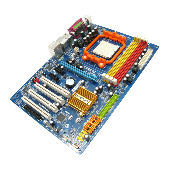
Page 7: Ga-M56S-S3 Motherboard Layout
GA-M56S-S3 Motherboard Layout KB_MS COAXIAL OPTICAL Socket AM2 ATX_12V CPU_FAN GA-M56S-S3 F_AUDIO AUDIO PCIE_16 RTL8211BL PCIE_1 BIOS BATTERY PCIE_2 nVIDIA ® CLR_CMOS PCI1 nForce 560 CODEC PCI2 PCI3 F_USB2 IT8716 TSB43AB23 F_USB1 PCI4 F_USB3 SYS_FAN F_PANEL F1_1394 F2_1394 PWR_LED - 7 -... -
Page 8: Block Diagram
Block Diagram CPU CLK+/-(200 MHz) PCIe CLK Socket AM2 (100 MHz) DDR2 800/667/533 MHz DIMM Dual Channel Memory Hyper Transport Bus PCI Express x16 RJ45 8211BL PCI Express Bus 4 SATA 3Gb/s nVIDIA ® ATA-133/100/66/33 nForce 560 IDE Channel PCIe CLK (100 MHz) BIOS 2 PCI Express x1... -
Page 9: Chapter 1 Hardware Installation
Chapter 1 Hardware Installation Installation Precautions The motherboard contains numerous delicate electronic circuits and components which can become damaged as a result of electrostatic discharge (ESD). Prior to installation, carefully read the user's manual and follow these procedures: Prior to installation, do not remove or break motherboard S/N (Serial Number) sticker or •... -
Page 10: Product Specifications
Support for Socket AM2 processors: AMD Athlon 64 FX processor/AMD Athlon 64 X2 Dual-Core processor/ AMD Athlon 64 processor/AMD Sempron processor (Go to GIGABYTE's website for the latest CPU support list.) Front Side Bus 2000 MHz FSB Chipset nVIDIA nForce 560 Chipset ®... - Page 11 Windows Vista/XP/2000 ® ® (Go to GIGABYTE's website for operating system support information.) Form Factor ATX Form Factor; 30.5cm x 21.4cm (Note 1) Based on standard PC architecture, a certain amount of memory is reserved for system usage and therefore the actual memory size is less than the stated amount. For example, 4 GB of memory size will instead be shown as 3.xx GB during system startup.
-
Page 12: Installing The Cpu And Cpu Cooler
Read the following guidelines before you begin to install the CPU: • Make sure that the motherboard supports the CPU. (Go to GIGABYTE's website for the latest CPU support list.) • Always turn off the computer and unplug the power cord from the power outlet before installing the CPU to prevent hardware damage. - Page 13 B. Follow the steps below to correctly install the CPU into the motherboard CPU socket. Before installing the CPU, make sure to turn off the computer and unplug the power cord from the power outlet to prevent damage to the CPU. CPU Socket Locking Lever Step 1:...
-
Page 14: Installing The Cpu Cooler
1-3-2 Installing the CPU Cooler Follow the steps below to correctly install the CPU cooler on the CPU. (The following procedure uses the GIGABYTE cooler as the example.) Step 1: Step 2: Apply an even and thin layer of thermal grease Place the CPU cooler on the CPU. -
Page 15: Installing The Memory
• Make sure that the motherboard supports the memory. It is recommended that memory of the same capacity, brand, speed, and chips be used. (Go to GIGABYTE's website for the latest memory support list.) • Always turn off the computer and unplug the power cord from the power outlet before installing the memory to prevent hardware damage. -
Page 16: Installing A Memory
Step 2: The clips at both ends of the socket will snap into place when the memory module is securely inserted. GA-M56S-S3 Motherboard - 16 -... -
Page 17: Installing An Expansion Card
Installing an Expansion Card Read the following guidelines before you begin to install an expansion card: • Make sure the motherboard supports the expansion card. Carefully read the manual that came with your expansion card. • Always turn off the computer and unplug the power cord from the power outlet before installing an expansion card to prevent hardware damage. -
Page 18: Back Panel Connectors
• When removing the cable, pull it straight out from the connector. Do not rock it side to side to prevent an electrical short inside the cable connector. GA-M56S-S3 Motherboard - 18 -... - Page 19 Center/Subwoofer Speaker Out Jack (Orange) Use this audio jack to connect center/subwoofer speakers in a 5.1/7.1-channel audio configuration. Rear Speaker Out Jack (Black) Use this audio jack to connect rear speakers in a 4/5.1/7.1-channel audio configuration. Side Speaker Out Jack (Gray) Use this audio jack to connect side speakers in a 7.1-channel audio configuration.
-
Page 20: Internal Connectors
• After installing the device and before turning on the computer, make sure the device cable has been securely attached to the connector on the motherboard. GA-M56S-S3 Motherboard - 20 -... - Page 21 1/2) ATX_12V/ATX (2x2 12V Power Connector and 2x12 Main Power Connector) With the use of the power connector, the power supply can supply enough stable power to all the components on the motherboard. Before connecting the power connector, first make sure the power supply is turned off and all devices are properly installed.
- Page 22 This connector is used to connect a floppy disk drive. The types of floppy disk drives supported are: 360 KB, 720 KB, 1.2 MB, 1.44 MB, and 2.88 MB. Before connecting a floppy disk drive, locate the foolproof groove on the connector. GA-M56S-S3 Motherboard - 22 -...
- Page 23 6) IDE (IDE Connector) The IDE connector supports up to two IDE devices such as hard drives and optical drives. Before attaching the IDE cable, locate the foolproof groove on the connector. If you wish to connect two IDE devices, remember to set the jumpers and the cabling according to the role of the IDE devices (for example, master or slave).
-
Page 24: Battery
• When installing the battery, note the orientation of the positive side (+) and the negative side (-) of the battery (the positive side should face up). • Used batteries must be handled in accordance with local environmental regulations. GA-M56S-S3 Motherboard - 24 -... -
Page 25: F_Panel
10) F_PANEL (Front Panel Header) Connect the power switch, reset switch, speaker and system status indicator on the chassis front panel to this header according to the pin assignments below. Note the positive and negative pins before connecting the cables. Message/Power/ Power Speaker... -
Page 26: Front Panel Audio Header
12) CD_IN (CD In Connector) You may connect the audio cable that came with your optical drive to the header. Pin No. Definition CD-L CD-R GA-M56S-S3 Motherboard - 26 -... - Page 27 13) SPDIF_I (S/PDIF In Header) This header supports digital S/PDIF in and can connect to an audio device that supports digital audio out via an optional S/PDIF in cable. For purchasing the optional S/PDIF in cable, please contact the local dealer. Pin No.
-
Page 28: Usb/Ieee 1394A Headers
• To connect an IEEE 1394a device, attach one end of the device cable to your computer and then attach the other end of the cable to the IEEE 1394a device. Ensure that the cable is securely connected. GA-M56S-S3 Motherboard - 28 -... -
Page 29: Chassis Intrusion Header
17) CI (Chassis Intrusion Header) This motherboard provides a chassis detection feature that detects if the chassis cover has been removed. This function requires a chassis with chassis intrusion detection design. Pin No. Definition Signal 18) CLR_CMOS (Clearing CMOS Jumper) Use this jumper to clear the CMOS values (e.g. - Page 30 GA-M56S-S3 Motherboard - 30 -...
-
Page 31: Chapter 2 Bios Setup
To see more advanced BIOS Setup menu options, you can press <Ctrl> + <F1> in the main menu of the BIOS Setup program. To upgrade the BIOS, use either the GIGABYTE Q-Flash or @BIOS utility. Q-Flash allows the user to quickly and easily upgrade or back up BIOS without entering the •... -
Page 32: Startup Screen
<TAB>: POST Screen <DEL>: BIOS Setup/Q-Flash <F9>: XpressRecovery2 <F12>: Boot Menu B. The POST Screen Award Modular BIOS v6.00PG, An Energy Star Ally Copyright (C) 1984-2007, Award Software, Inc. GA-M56S-S3 D1 Motherboard Model BIOS Version Function Keys <DEL>: BIOS Setup/Q-Flash <F9>: XpressRecovery2 <F12>: Boot Menu <End>: Qflash... -
Page 33: The Main Menu
The Main Menu Once you enter the BIOS Setup program, the Main Menu (as shown below) appears on the screen. Use arrow keys to move among the items and press <Enter> to accept or enter a sub-menu. (Sample BIOS Version: D1) CMOS Setup Utility-Copyright (C) 1984-2007 Award Software Standard CMOS Features Load Fail-Safe Defaults... - Page 34 (Pressing <F10> can also carry out this task.) Exit Without Saving Abandon all changes and the previous settings remain in effect. Pressing <Y> to the confirmation message will exit BIOS Setup. (Pressing <Esc> can also carry out this task.) GA-M56S-S3 Motherboard - 34 -...
-
Page 35: Standard Cmos Features
Standard CMOS Features CMOS Setup Utility-Copyright (C) 1984-2007 Award Software Standard CMOS Features Date (mm:dd:yy) Fri, Jun 22 2007 Item Help Time (hh:mm:ss) 22:31:24 Menu Level IDE Channel 0 Master [None] IDE Channel 0 Slave [None] IDE Channel 2 Master [None] IDE Channel 2 Slave [None]... - Page 36 These fields are read-only and are determined by the BIOS POST. Base Memory Also called conventional memory. Typically, 640 KB will be reserved for the MS-DOS operating system. Extended Memory The amount of extended memory. GA-M56S-S3 Motherboard - 36 -...
-
Page 37: Advanced Bios Features
Advanced BIOS Features CMOS Setup Utility-Copyright (C) 1984-2007 Award Software Advanced BIOS Features AMD K8 Cool&Quiet control [Auto] Item Help Hard Disk Boot Priority [Press Enter] Menu Level First Boot Device [Floppy] Second Boot Device [Hard Disk] Third Boot Device [CDROM] Password Check [Setup]... - Page 38 Sets the PCI graphics card as the first display. (Default) Sets PCI Express graphics card as the first display. Full Screen LOGO Show Allows you to determine whether to display the GIGABYTE Logo at system startup. Disabled displays normal POST message. (Default: Enabled) GA-M56S-S3 Motherboard...
-
Page 39: Integrated Peripherals
Integrated Peripherals CMOS Setup Utility-Copyright (C) 1984-2007 Award Software Integrated Peripherals Serial-ATA RAID Config [Press Enter] Item Help On-Chip IDE Channel0 [Enabled] Menu Level IDE DMA transfer access [Enabled] On-Chip MAC Lan [Auto] NV Serial-ATA 1 [Enabled] IDE Prefetch Mode [Enabled] USB Memory Type [SHADOW]... - Page 40 Enables or disables the integrated SATA controllers. (Default: Enabled) IDE Prefetch Mode Enables or disbales prefetch mode for the integrated IDE controller. Enabled activates the IDE prefetch buffer to enhance hard drive performance. (Default: Enabled) GA-M56S-S3 Motherboard - 40 -...
- Page 41 USB Memory Type Specifies the type of memory allocated for USB devices. Options are: SHADOW (default), Base Memory (640K). Onchip SATA Mode Enables or disables RAID for the SATA controller integrated in the nVIDIA nForce 560 chipset or ® configures the SATA controller to AHCI mode. Disables RAID for the SATA controller and configures the SATA controller to PATA mode.
- Page 42 ECP Mode Use DMA Selects DMA channel for the LPT port in ECP mode. This item is configurable only if Parallel Port Mode is set to ECP or ECP+EPP mode. Options are: 3 (default), 1. GA-M56S-S3 Motherboard - 42 -...
- Page 43 On-Chip USB Controller Configures the integrated USB controller. V1.1+V2.0 Enables the integrated USB 1.1 and USB 2.0 controllers. (Default) V1.1 Enables only the integrated USB 1.1 controller. Disabled Disables the integrated USB 1.1 and USB 2.0 controllers. Disabled will turn off all of the USB functionalities below. USB Keyboard Support Allows USB keyboard to be used in MS-DOS.
-
Page 44: Power Management Setup
Modem Ring On Allows the system to be awakened from an ACPI sleep state by a wake-up signal from a modem that supports wake-up function. (Default: Enabled) (Note) Supported on Windows Vista operating system only. ® ® GA-M56S-S3 Motherboard - 44 -... - Page 45 USB Resume from Suspend Allows the system to be awakened from ACPI S3 sleep state by a wake-up signal from the installed USB device. (Default: Enabled) Power On by Alarm Determines whether to power on the system at a desired time. (Default: Disabled) If enabled, set the date and time as following: Day of Month Alarm : Turn on the system at a specific time on each day or on a specific day in a month.
-
Page 46: Pnp/Pci Configurations
BIOS auto-assigns IRQ to the third PCI slot. (Default) 3,4,5,7,9,10,11,12,14,15 Assigns IRQ 3,4,5,7,9,10,11,12,14,15 to the third PCI slot. PCI4 IRQ Assignment Auto BIOS auto-assigns IRQ to the fourth PCI slot. (Default) 3,4,5,7,9,10,11,12,14,15 Assigns IRQ 3,4,5,7,9,10,11,12,14,15 to the fourth PCI slot. GA-M56S-S3 Motherboard - 46 -... -
Page 47: Pc Health Status
PC Health Status CMOS Setup Utility-Copyright (C) 1984-2007 Award Software PC Health Status Reset Case Open Status [Disabled] Item Help Case Opened Menu Level Vcore DDR2 1.8V +3.3V +12V Current System Temperature Current CPU Temperature Current CPU FAN Speed 3245 RPM Current SYSTEM FAN Speed 0 RPM System Warning Temperature... - Page 48 Enables or disables the system fan speed control function. Enabled allows the system fan to run at different speed according to the system temperature. You can adjust the fan speed with EasyTune based on system requirements. If disabled, system fan runs at full speed. (Default: Enabled) GA-M56S-S3 Motherboard - 48 -...
-
Page 49: Mb Intelligent Tweaker(M.i.t.)
MB Intelligent Tweaker(M.I.T.) CMOS Setup Utility-Copyright (C) 1984-2007 Award Software MB Intelligent Tweaker(M.I.T.) CPU Frequency [200] Item Help PCIE Clock [100Mhz] Menu Level CPU Clock Ratio [Auto] Robust Graphics Booster [Auto] Chipset Voltage Control [Normal] DDR2 Voltage Control [Auto] CPU Voltage Control [Normal] Normal CPU Vcore 1.3500V... - Page 50 CPU being installed. (Default: Normal) Note: Increasing CPU voltage may result in damage to your CPU or reduce the useful life of the CPU. Normal CPU Vcore Displays the normal operating voltage of your CPU. GA-M56S-S3 Motherboard - 50 -...
-
Page 51: Load Fail-Safe Defaults
2-10 Load Fail-Safe Defaults CMOS Setup Utility-Copyright (C) 1984-2007 Award Software Standard CMOS Features Load Fail-Safe Defaults Advanced BIOS Features Load Optimized Defaults Integrated Peripherals Set Supervisor Password Power Management Setup Set User Password Load Fail-Safe Defaults (Y/N)? N PnP/PCI Configurations Save &... -
Page 52: Set Supervisor/User Password
BIOS settings but not to make changes. To clear the password, press <Enter> on the password item and when requested for the password, press <Enter> again. The message "PASSWORD DISABLED" will appear, indicating the password has been cancelled. GA-M56S-S3 Motherboard - 52 -... -
Page 53: Save & Exit Setup
2-13 Save & Exit Setup CMOS Setup Utility-Copyright (C) 1984-2007 Award Software Standard CMOS Features Load Fail-Safe Defaults Advanced BIOS Features Load Optimized Defaults Integrated Peripherals Set Supervisor Password Save to CMOS and EXIT (Y/N)? Y Power Management Setup Set User Password PnP/PCI Configurations Save &... - Page 54 GA-M56S-S3 Motherboard - 54 -...
-
Page 55: Chapter 3 Drivers Installation
Chapter 3 Drivers Installation • Before installing the drivers, first install the operating system. (The following instructions use Windows XP as the example operating system.) • After installing the operating system, insert the motherboard driver disk into your optional drive. The driver Autorun screen is automatically displayed which looks like that shown in the screen shot below. -
Page 56: Software Applications
Software Applications This page displays all the tools and applications that GIGABYTE develops and some free software. You may press the Install button following an item to install it. Driver CD Information This page provides information about the drivers, applications and tools in this driver disk. -
Page 57: Hardware Information
Hardware Information This page provides information about the hardware devices on this motherboard. Contact Us Check the contacts information of the GIGABYTE headquarter in Taiwan and the overseas branch offices on the last page of this manual. - 57 -... - Page 58 GA-M56S-S3 Motherboard - 58 -...
-
Page 59: Chapter 4 Unique Features
Chapter 4 Unique Features Xpress Recovery2 Xpress Recovery2 is an utility that allows you to quickly compress and back up your system data and perform restoration of it. Supporting NTFS, FAT32, and FAT16 file systems, Xpress Recovery2 can back up data on PATA and SATA hard drives and restore it. Before You Begin: •... - Page 60 Recovery2 (10 GB or more is recommended; actual size requirements vary, depending on the amount of data) (Figure 2). Figure 2 Figure 1 3. Select a file system (for example, NTFS) and begin the installation of the operating system (Figure 3). Figure 3 GA-M56S-S3 Motherboard - 60 -...
- Page 61 4. After the operating system is installed, right-click the My Computer icon on your desktop and select Manage (Figure 4). Go to Computer Management to check disk allocation. Xpress Recovery2 will save the backup file to the unallocated space (black stripe along the top)(Figure 5). Please note that if there is no enough unallocated space, Xpress Recovery2 cannot save the backup file.
- Page 62 If you wish to enter Xpress Recovery2 later, simply press <F9> during the POST (Figure 9). Award Modular BIOS v6.00PG, An Energy Star Ally Copyright (C) 1984-2007, Award Software, Inc. GA-M56S-S3 D1 <DEL>: BIOS Setup/Q-Flash <F9>: XpressRecovery2 <F12>: Boot Menu <End>: Qflash Figure 9 06/22/2007-NF-MCP65-6A61LG01C-00 C.
- Page 63 D. Using the Restore Function in Xpress Recovery2 Select RESTORE to restore the backup to your hard drive in case the system breaks down. The RESTORE option will not be present if no backup is created before (Figure 13, 14). Figure 13 Figure 14 E.
-
Page 64: Bios Update Utilities
4-2-1 Updating the BIOS with the Q-Flash Utility A. Before You Begin: 1. From GIGABYTE's website, download the latest compressed BIOS update file that matches your motherboard model. 2. Extract the file and save the new BIOS file (e.g. M56SS3.F1) to your floppy disk, USB flash drive, or hard drive. - Page 65 B. Updating the BIOS When updating the BIOS, choose the location where the BIOS file is saved. The follow procedure assumes that you save the BIOS file to a floppy disk. Step 1: 1. Insert the floppy disk containing the BIOS file into the floppy disk drive. In the main menu of Q- Flash, use the up or down arrow key to select Update BIOS from Drive and press <Enter>.
- Page 66 Load Optimized Defaults Press <Y> to load BIOS defaults Step 6: Select Save & Exit Setup and then press <Y> to save settings to CMOS and exit BIOS Setup. The procedure is complete after the system restarts. GA-M56S-S3 Motherboard - 66 -...
-
Page 67: Updating The Bios With The @Bios Utility
BIOS or a system that is unable to start. 3. Do not use the C.O.M. (Corporate Online Management) function when using @BIOS. 4. GIGABYTE product warranty does not cover any BIOS damage or system failure resulting from an inadequate BIOS flashing. - Page 68 • If the BIOS update file for your motherboard is not present on the @BIOS server site, please manually download the BIOS update file from GIGABYTE's website and follow the instructions in "Update the BIOS without Using the Internet Update Function" below.
-
Page 69: Easytune 5
Toggles between Easy and Advance Mode Display Field Displays panel of CPU frequency Function LEDs Shows the information of the current function GIGABYTE Logo Visits GIGABYTE website Help Displays EasyTune 5 help screen Exit or Minimize Quits or minimizes EasyTune Incorrectly doing overclock/overvoltage may result in damage to CPU, chipset, or memory and reduce the useful life of these components. -
Page 70: Windows Vista Readyboost
• The USB flash drive must have at least 256 MB of space. • The recommended amount of memory to use for ReadyBoost acceleration is one to three times the amount of RAM installed in your computer. GA-M56S-S3 Motherboard - 70 -... -
Page 71: Chapter 5 Appendix
Chapter 5 Appendix Configuring SATA Hard Drive(s) To configure SATA hard drive(s), follow the steps below: A. Install SATA hard drive(s) in your computer. B. Configure SATA controller mode in BIOS Setup. C . Configure a RAID array in RAID BIOS. (Note 1) D. - Page 72 The BIOS Setup menus described in this section may differ from the exact settings for your motherboard. The actual BIOS Setup menu options you will see shall depend on the motherboard you have and the BIOS version. GA-M56S-S3 Motherboard - 72 -...
- Page 73 C. Configuring RAID set in RAID BIOS Enter the RAID BIOS setup utility to configure a RAID array. For a non-RAID configuration, please skip this step and proceed to the installation of Windows operating system. Step 1: After the POST memory test begins and before the operating system boot begins, look for a message which says "Press F10 to enter RAID setup utility"...
- Page 74 Clear disk data ? 1.0.M ST3120026AS 111.79GB [Y] YES [N] NO 1.1.M ST3120026AS 111.79GB [ ] Add [Y] YES [N] NO [ ] Del [ESC] Quit [F6] Back [F7] Finish [TAB] Navigate ] Select [ENTER] Popup Figure 6 GA-M56S-S3 Motherboard - 74 -...
- Page 75 After that, the Array List screen appears, displaying the RAID array that you have created (Figure 7). (Note: BBS stands for BIOS Boot Specification. This indicates that the boot device is defined in the BIOS.) MediaShield Utility Apr 20 2007 - Array List - Boot Status...
-
Page 76: Making A Sata Raid/Ahci Driver Diskette
Use an alternative system and insert the motherboard driver disk. From your optical drive folder, double click the MENU.exe file in the BootDrv folder (Figure 3). A command prompt window will open similar to that in Figure 2. Figure 3 GA-M56S-S3 Motherboard - 76 -... -
Page 77: Installing The Sata Raid/Ahci Driver And Operating System
5-1-3 Installing the SATA RAID/AHCI Driver and Operating System Now that you have prepared the SATA RAID/AHCI driver diskette and configured the required BIOS settings, you are ready to install Windows Vista/XP/2000 onto your hard drive(s). The following is an example of Windows XP and Vista installation. - Page 78 If a message appears saying one or some file(s) cannot be found, please check the floppy disk or copy the correct SATA RAID driver again from the motherboard driver disk. (Note) The selectable item(s) displayed in Figure 3 may differ according to the RAID or AHCI driver you will install. GA-M56S-S3 Motherboard - 78 -...
- Page 79 When the screen as shown below appears, press <Enter> to continue the driver installation from the floppy disk. The driver installation will be finished in about one minute. Windows Setup Setup will load support for the following mass storage device(s): NVIDIA RAID Driver (required) NVIDIA nForce Storage Controller (required) * To specify additional SCSI adapters, CD-ROM drives, or special...
- Page 80 When a screen similar to that below appears (RAID or AHCI hard drive(s) will not be detected at this stage), select Load Drivers. (Figure 6). Figure 6 Step 2: Specify the location where the driver is saved, such as your floppy disk (Figure 7). Figure 7 GA-M56S-S3 Motherboard - 80 -...
- Page 81 Step 3: When installing the RAID driver, for example, when a screen as shown in Figure 8 appears, select (Note) NVIDIA nForce RAID Controller and press Next. Later, the screen will return to that in Figure 8. Select NVIDIA nForce Serial ATA Controller and press Next. Figure 8 Step 4: After the driver is loaded, the screen will show the RAID or AHCI hard drive(s).
-
Page 82: Configuring Audio Input And Output
• 4 channel audio: Front speaker out and Rear speaker out. • 5.1 channel audio: Front speaker out, Rear speaker out, and Center/Subwoofer speaker out. • 7.1 channel audio: Front speaker out, Rear speaker out, Center/Subwoofer speaker out, and Side speaker out. GA-M56S-S3 Motherboard - 82 -... - Page 83 Step 2: Click the Audio I/O tab. In the speaker list on the left, select 2CH Speaker, 4CH Speaker, 6CH Speaker, or 8CH Speaker according to the type of speaker configuration you wish to set up. Step 3: Everytime you connect an audio device to an audio jack, the Connected device box appears.
-
Page 84: Installing The S/Pdif In Cable (Optional)
A. Installing the S/PDIF In Cable: Step 1: First, attach the connector at the end of the cable to the SPDIF_IN header on your motherboard. Step 2: Secure the metal bracket to the chassis back panel with a screw. GA-M56S-S3 Motherboard - 84 -... - Page 85 S/PDIF Out: The S/PDIF out jacks can transmit audio signals to an external decoder for decoding to get the best audio quality. B. Conneting a S/PDIF out Cable Connect a S/PDIF coaxial cable or a S/PDIF optical cable (either one) to an external decoder for transmitting the S/PDIF digital audio signals.
-
Page 86: Configuring Microphone Recording
Note: The microphone functions on the front panel and back panel cannot be used at the same time. Step 3: Locate the Volume icon in your system tray and click it to open the volume control panel GA-M56S-S3 Motherboard - 86 -... - Page 87 Step 4: To hear the sound being recorded during the record- ing process when using the microphone function on the front panel, do not select the Mute check box under Front Pink In or Front Green In in Master Volume. It is recommended that you set the volume at a middle level.
-
Page 88: Using The Sound Recorder
3. To play a sound file, click the Play button 4. To stop playing, click the Stop button 5. You may use the Fast Forward button move to the beginning of a file or the Fast Back- ward button to the end. GA-M56S-S3 Motherboard - 88 -... -
Page 89: Troubleshooting
5-3-1 Frequently Asked Questions To read more FAQs for your motherboard, please go to the Support\Motherboard\FAQ page on GIGABYTE's website. Q: In the BIOS Setup program, why are some BIOS options missing? A: Some advanced options are hidden in the BIOS Setup program. Press <Delete> to enter BIOS Setup during the POST. -
Page 90: Troubleshooting Procedure
Turn on the power to start the computer. Press <Delete> to enter BIOS Setup. Select "Load Fail-Safe Defaults" (or "Load Optimized Defaults"). Select "Save & Exit Setup" to save changes and exit BIOS Setup. (Continued...) GA-M56S-S3 Motherboard - 90 -... - Page 91 The power supply, When the computer is turned on, is the CPU cooler running? CPU or CPU socket might fail. The problem is verified and solved. The graphics card, expansion slot, or Check if there is display on your monitor. monitor might fail.
-
Page 92: Regulatory Statements
"end of life" product. Restriction of Hazardous Substances (RoHS) Directive Statement GIGABYTE products have not intended to add and safe from hazardous substances (Cd, Pb, Hg, Cr+6, PBDE and PBB). The parts and components have been carefully selected to meet RoHS requirement. - Page 93 Finally, we suggest that you practice other environmentally friendly actions by understanding and using the energy-saving features of this product (where applicable), recycling the inner and outer packaging (including shipping containers) this product was delivered in, and by disposing of or recycling used batteries properly.
- Page 94 GA-M56S-S3 Motherboard - 94 -...
- Page 95 Shenyang Web address: http://latam.giga-byte.com/ TEL: +86-24-83992901 GIGA-BYTE SINGAPORE PTE. LTD. - Singapore FAX: +86-24-83992909 WEB address : http://www.gigabyte.sg GIGABYTE TECHNOLOGY (INDIA) LIMITED - India Thailand WEB address : http://www.gigabyte.in WEB address : http://th.giga-byte.com Saudi Arabia Vietnam WEB address : http://www.gigabyte.com.sa WEB address : http://www.gigabyte.vn...
- Page 96 WEB address : http://www.giga-byte.gr WEB address : http://www.giga-byte.kz Czech Republic You may go to the GIGABYTE website, select your language WEB address : http://www.gigabyte.cz in the language list on the top right corner of the website. GIGABYTE Global Service System...
Need help?
Do you have a question about the GA-M56S-S3 and is the answer not in the manual?
Questions and answers