Advertisement
Quick Links
1
Introduction
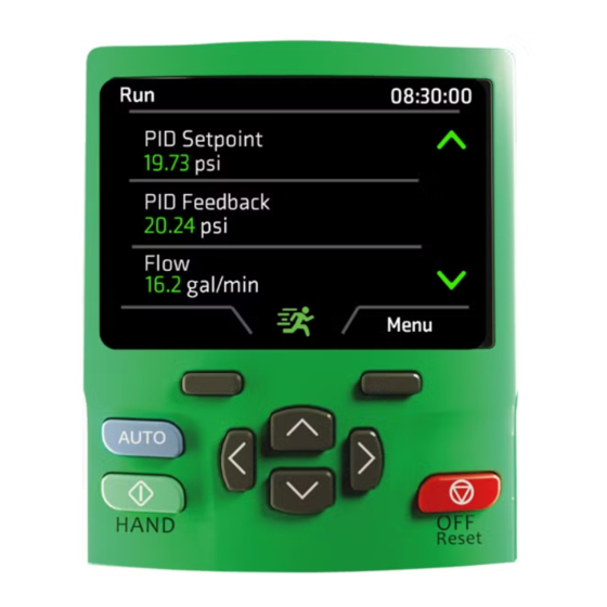
The KI-Keypad Plus provides a user interface for a range of Control
Techniques drives.
1.1
Features
The KI-Keypad Plus has the following features:
•
2.8" TFT color LCD screen.
•
Clear parameter names and descriptions.
•
Intuitive navigation for drive and option module menus and
parameters.
•
Provides Bluetooth interface for wireless communication with the
drive from a PC.
•
Real time clock.
•
Remote mountable.
•
User configurable status screen showing up to 8 parameters
including user defined scaling and units.
•
Multiple languages supported.
•
Provides simple access to 'Quick Actions' such as saving
parameters and defaulting the drive.
•
Provides drive and application 'FastStart' actions for rapid
commissioning.
1.2
Compatible drives
The KI-Keypad Plus is supported by several drives, either fitted directly
on to the drive or used as a remote keypad via a 485 serial
communications interface. The table below shows the compatible drives.
Table 1-1 Compatible drives
Mountable
Drive
on the drive
Unidrive M600, M701 Yes
Powerdrive F300
Yes
Elevator E300
Yes
Unidrive M700, M702 Yes
HVAC drive H300
Yes
Pump drive F600
Yes
Digitax HD
No
Commander C200/
No
C300
Unidrive M400
No
2
Installation
The KI-Keypad Plus is intended for use when directly
attached to the drive or when mounted on a cubicle door in
the manner shown in this installation sheet. It is not suitable
for handheld use. Operation in any other fashion may cause
WARNING
a hazard and invalidates the warranty.
Figure 2-1 Drive mounting of the KI-Keypad Plus
To install, align the keypad and press gently in the direction shown until it
clicks into position. To remove, reverse the installation instructions.
KI Keypad Plus User Guide / Installation Sheet
Supports Remote Keypad
Yes
Yes
Yes
Yes, when using the KI-485 Adaptor
Yes, when using the KI-485 Adaptor
Yes, when using the KI-485 Adaptor
Yes, when using the KI-Compact 485
Adaptor
Yes, when using the AI-485 Adaptor
Yes, when using the AI-485 Adaptor or CI-
485 Adaptor and firmware V01.05.00.xx
or newer.
NOTE
The KI-Keypad Plus can be installed or removed while the drive is
powered up and running a motor, provided that the drive is not operating
in keypad mode.
2.1
Panel mounting of the KI-Keypad Plus
Figure 2-2 shows the dimensions of the cut-out required to mount the KI-
Keypad Plus on a panel or cubicle door.
Figure 2-2 Panel cut out
Ø10 mm (0.39 in)
Figure 2-3 Panel mounting
3
5
4
1. Fit the rubber seal around the keypad.
2. Position the keypad into the panel / cubicle cut-out.
3. Attach clamping bracket.
4. Insert the 3 x mounting screws and tighten to 0.6 N m (5.3 lb in).
5. Insert the 6-pin connector cover.
The KI-Keypad Plus has an 8P8C connector on the rear for remote
communications connection to the drive. The communications cable
between the keypad and the drive's 485 serial port should be wired one-
to-one.
The maximum cable length is 100 m when conductors of 0.129 mm
(AWG 26) or larger are used and the cable shield is connected to the
grounded panel / cubicle at the keypad end of the cable. It is
recommended that the cable uses the following twisted pairs: 1-8, 2-7,
3-6, and 4-5.
The 6-pin connector cover must be installed to prevent
exposure to electrical circuits that may only be protected to
ELV levels depending upon the type of drive used.
WARNING
TOP
5 mm (2.2 in)
7
4
6
7 mm
(2.6 in)
3
1
2
0478-0738-02
2
Advertisement

Subscribe to Our Youtube Channel
Related Manuals for Nidec KI Keypad Plus


Summary of Contents for Nidec KI Keypad Plus
- Page 1 KI Keypad Plus User Guide / Installation Sheet Introduction The KI-Keypad Plus provides a user interface for a range of Control NOTE Techniques drives. The KI-Keypad Plus can be installed or removed while the drive is powered up and running a motor, provided that the drive is not operating Features in keypad mode.
- Page 2 Understanding the Keypad Icons Figure 3-1 KI-Keypad Plus (Grey) Part number 8240000002270 The top right corner of the display on the KI-Keypad Plus can show several different status icons. Table 3-1 below details the meaning of these icons. Table 3-1 Status icons Icon Description Alarm active...
- Page 3 Keypad Menus 7. Connect will then ask for the Bluetooth pairing code. This will be shown on the display of the keypad for approximately 10 seconds. If The keypad menus can be found by going to: Main Menu > Keypad the code needs to be displayed again, click cancel and tick the Menu.
Need help?
Do you have a question about the KI Keypad Plus and is the answer not in the manual?
Questions and answers