Table of Contents
Advertisement
Available languages
Available languages
Quick Links
VENT-FREE GAS
DUAL FUEL FIREPLACE
MODEL # VFF3-26PHDX
VFF3-26PHDZ
VFF3-26PHDX
Patent Pending
Dual Fuel System
NG
LP
Dual Fuel
VFF3-26PHDZ
C
US
C
US
ANS Z21.11.2 2019
INSTALLER: Leave this manual with the appliance.
CONSUMER: Retain this manual for future reference.
WARNING: This appliance is equipped for (Natural and Propane) gas. Field conversion is not
permitted other than between natural or propane gases.
Questions, problems, missing parts? Before returning to your retailer, call our customer
service department at 1-877-447-4768, 8:30 a.m. – 4:30 p.m., CST, Monday – Friday.
You could also contact us at customerservice@ghpgroupinc.com.
1
IM80-01-259 - 2024-05-10
Advertisement
Table of Contents

Subscribe to Our Youtube Channel
Related Manuals for pleasant hearth VFF3-26PHDX


Summary of Contents for pleasant hearth VFF3-26PHDX
- Page 1 VENT-FREE GAS DUAL FUEL FIREPLACE MODEL # VFF3-26PHDX VFF3-26PHDZ VFF3-26PHDX Patent Pending Dual Fuel System Dual Fuel VFF3-26PHDZ ANS Z21.11.2 2019 INSTALLER: Leave this manual with the appliance. CONSUMER: Retain this manual for future reference. WARNING: This appliance is equipped for (Natural and Propane) gas. Field conversion is not permitted other than between natural or propane gases.
-
Page 2: What To Do If You Smell Gas
CAUTION - FOR YOUR SAFETY WARNING: IF THE INFORMATION IN THIS MANUAL IS NOT FOLLOWED EXACTLY, A FIRE OR EXPLOSION MAY RESULT CAUSING PROPERTY DAMAGE, PERSONAL INJURY OR LOSS OF LIFE. - Do not store or use gasoline or other flammable vapors and Iiquids in vicinity of this or any other appliance. -
Page 3: Table Of Contents
TABLE OF CONTENTS Specifications ........................... 3 Important Safety Information ......................4 Product Identification ........................6 Product Features ..........................8 Unpacking............................8 Assembly ............................9 Preparing for Installation......................... 10 Installation and Blower Installation ....................13 Operation ............................28 Care and Maintenance ........................30 Troubleshooting .......................... -
Page 4: Important Safety Information
IMPORTANT SAFETY INFORMATION WARNING: FIRE, EXPLOSION, AND ASPHYXIATION HAZARD Improper adjustment, alteration, service, maintenance, or installation of this heater or its controls can cause death or serious injury. Read and follow instructions and precautions in User's Information Manual provided with this heater. IMPORTANT: Read this owner’s manual carefully and completely before trying to assemble, operate, or service this heater. -
Page 5: Safety Information
SAFETY INFORMATION 1. This appliance is only for use with the type of gas indicated on the rating plate. This appliance is not convertible for use with other gases. 2. Do not place propane/LP supply tank(s) inside any structure. Locate propane/LP supply tank(s) outdoors. 3. -
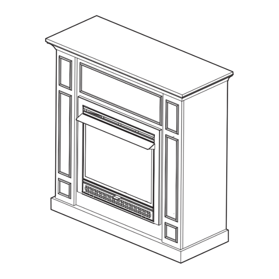
Page 6: Product Identification
PRODUCT IDENTIFICATION NOTE: The fireplace is installed into the mantel through the front opening of the mantel cabinet. WARNING: This fireplace is designed for use with the mantel cabinet provided. Installing the fireplace cabinet without the provided mantel or substituting another mantel will void the warranty and could result in property damage and personal injury. - Page 7 PRODUCT IDENTIFICATION VFF3-26PHDX VFF3-26PHDZ PART DESCRIPTION PART DESCRIPTION Top Panel Top Panel Base Base Side Panel Left Side Panel Upper Front Panel Right Side Panel Left Front Panel Left Front Panel Right Front Panel Right Front Panel Platform Panel Upper Front Panel...
-
Page 8: Product Features
PRODUCT FEATURES SAFETY PILOT This heater has a pilot with an Oxygen Depletion Sensing (ODS) safety shutoff system. The ODS/pilot shuts off the heater if there is not enough fresh air and cuts off main burner gas in the event of flame out. ELECTRIC PUSH BUTTON IGNITION SYSTEM This heater is equipped with an electronic push button control system. -
Page 9: Assembly
Carefully lift the insert through the center opening in the front of the fireplace. Slide the insert back through the opening until the metal trim makes contact with the front of the mantel. VFF3-26PHDX VFF3-26PHDZ Fig. 2 - Insert Firebox... -
Page 10: Preparing For Installation
PREPARING FOR INSTALLATION AIR FOR COMBUSTION AND VENTILATION WARNING: This heater shall not be installed in a room or space unless the required volume of indoor combustion air is provided by the method described in the Nation Fuel Gas Code, ANSI Z223.1/NFPA 54, the International Fuel Gas Code, or applicable local codes. - Page 11 PREPARING FOR INSTALLATION DETERMINING FRESH-AIR FLOW FOR HEATER LOCATION Determining if You Have a Confined or Unconfined Space Use this worksheet to determine if you have a confined or unconfined space. Space: Includes the room in which you will install heater plus any adjoining rooms with doorless passageways or ventilation grills between the rooms.
- Page 12 PREPARING FOR INSTALLATION Ventilation Air From Inside Building This fresh air would come from adjoining unconfined space. When ventilating to an adjoining unconfined space, you must provide two permanent openings: one within 12 in. of the wall connecting the two spaces (see options 1 and 2, Fig.
-
Page 13: Installation
INSTALLATION NOTICE: This heater is intended for use as supplemental heat. Use this heater along with your primary heating system. Do not install this heater as your primary heat source. WARNING: A qualified technician must install heater. Follow all local codes. WARNING: Never install the heater: •... - Page 14 INSTALLATION FIREPLACE CLEARANCES CAUTION: If you install the fireplace in a home garage • Fireplace pilot and burner must be at least 18" above floor. • Locate fireplace where moving vehicle will not hit it. For convenience and efficiency, install fireplace •...
- Page 15 BLOWER ASSEMBLY (OPTIONAL) INSTALLATION WARNING: This optional blower is equipped with a three-prong (grounding) plug for your WARNING: This optional blower is equipped with a three-prong (grounding) plug for protection against shock hazard and must be plugged directly into a properly grounded your protection against shock hazard and must be plugged directly into a properly three-prong receptacle.
- Page 16 BLOWER ASSSEMBLY (CONTINUED) INSTALLATION Important: Insert the wires marked Important: Insert the wires marked with AUTO, with AUTO, OFF and MAN into line OFF and MAN into line slot on the right corner. slot on the right corner. Keep wires Keep wires close to the bottom and guide to the close to the bottom and guide to front using the bottom access.
- Page 17 INSTALLATION BLOWER ASSSEMBLY (CONTINUED) Insert the blower link (male plug) Insert the blower link (male plug) into the power into the power link (female port). link (female port). : Bind wires with cable 10. Important: Bind wires with cable tie (G), and tie (G), and attach cable tie (G) attach cable tie (G) side of the Outer Casing.
- Page 18 BLOWER ASSSEMBLY (CONTINUED) INSTALLATION 13. Push Rocker Switch (E) into Control Panel and Push Rocker Switch (E) into secure. Control Panel and secure. 14. Secure the Green Ground wire to the Grounding Secure the Green Ground wire to screw hole from the inside with the screw. the Grounding screw hole from Screw the inside with the screw.
- Page 19 BLOWER ASSSEMBLY (CONTINUED) INSTALLATION Electrical Wiring Diagram WHITE ~120V 60Hz GREEN BLACK AUTO OFF MAN 1. Power Cord 2. Bushing Strain Relief 3. Blower 4. Temperature Sensor 5. Rocker Switch NOTE: If any of the original wire as supplied with the appliance must be replaced, it must be NOTE: If any of the original wire as supplied with the appliance must be replaced, it must be replaced with a wire of at least an equal temperature rating.
- Page 20 INSTALLATION - VFF3-26PHDX NOTE: If you have model #VFF3-26PHDZ, please skip to page 23. Tools Required: • Phillips screwdriver (not included) Secure 14 connectors (AA) to the left and right side panels (C) using 28 short bolts (BB). Connect the left front panel (E) to left side panel (C) with 3 short bolts (BB).
- Page 21 INSTALLATION - VFF3-26PHDX Connect the platform panel (G) to the long side of the base (B) using 2 short bolts (BB). Connect the left and right (C) side panels to the base (B) using 4 short bolts (BB). Connect the upper front panel to the left (E) and right (F) front panels using 4 dowels (EE), 4 long bolts (CC) and 4 washers (DD).
- Page 22 INSTALLATION - VFF3-26PHDX Connect the top panel (A) to the left and right (C) side panels and the upper front panel (D) using 6 short bolts (BB). Secure 4 connectors (AA) to the 4 support panels (H) using 8 short bolts (BB).
- Page 23 INSTALLATION - VFF3-26PHDZ Tools Required: • Phillips screwdriver (not included) Secure 8 connectors (AA) to the short sides of the left (C) and right (D) side panels using 16 short bolts (BB). Secure 6 connectors (AA) to the left (E) and right (F) front panels using 12 short bolts (BB).
- Page 24 INSTALLATION - VFF3-26PHDZ Connect the left (C) and right (D) side panels and the left (E) and right (F) front panels to the base (B) using 6 short bolts (BB). Secure 4 connectors (AA) to the upper front panel (G) using 8 short bolts (BB). Connect the upper front panel (G) to the left (E) and right (F) front panels using 2 short bolts (BB).
- Page 25 INSTALLATION - VFF3-26PHDZ Connect the platform panel (H) to the left (E) and right (F) front panels using 2 long bolts (CC) and 2 washers (DD). Connect the top panel (A) to the left (C) and right (D) side panel and the upper front panel (G) using 6 short bolts (BB).
- Page 26 INSTALLATION GAS SELECTION INSTRUCTIONS WARNING: This appliance can be used with propane or natural gas. It is shipped from the factory adjusted for use with propane. CAUTION: The knob to the gas selection means shall not be accessed or adjusted while the appliance is in operation.
-
Page 27: Connecting To Gas Supply
INSTALLATION CONNECTING TO GAS SUPPLY WARNING: A qualified service technician must connect heater to gas supply. Follow all local codes. CAUTION: Never connect heater directly to the gas supply. This heater requires an external regulator (not supplied). The external regulator between the gas supply and heater must be installed. Gas supplier provides external regulator for natural gas. - Page 28 INSTALLATION CAUTION: Use pipe joint sealant that is resistant to gas (PROPANE or NG). We recommend that you install a sediment trap in a supply line as shown in Fig. 10. Locate sediment trap where it is within reach for cleaning and not likely to freeze. Install in the piping system between fuel supply and heater.
-
Page 29: Assembling Logs
ASSEMBLING LOGS WARNING: Failure to position the parts in accordance with these diagrams or failure to use only parts specifically approved with this heater may result in property damage or personal injury. CAUTION: After installation and periodically thereafter, check to ensure that no yellow flame comes in contact with any log. -
Page 30: Checking Gas Connections
INSTALLATION CHECKING GAS CONNECTIONS WARNING: Test all gas piping and connections for leaks after installing or servicing. Correct all leaks immediately. WARNING: Never use an open flame to check for a leak. Apply a mixture of liquid soap and water to all joints. -
Page 31: Operation
OPERATION FOR YOUR SAFETY; READ BEFORE LIGHTING WARNING: If you do not follow these instructions exactly, a fire or explosion may result causing property damage, personal injury or loss of life. A. This appliance has a pilot which must be lighted by the electronic ignitor. When lighting the pilot, follow these instructions exactly. -
Page 32: Inspecting Burners
OPERATION TO TURN OFF GAS TO APPLIANCE 1. Open the lower access panel located under the fireplace screen. 2. Turn control knob clockwise to the “OFF” position. 3. Close lower access panel. INSPECTING BURNERS Check pilot flame pattern and burner flame patterns often. PILOT FLAME PATTERN Figure 20 shows a correct pilot flame pattern. -
Page 33: Care And Maintenance
CARE AND MAINTENANCE BURNER FLAME PATTERN Figure 22 shows a correct burner flame pattern. Figure 23 shows an incorrect burner flame pattern. The incorrect burner flame pattern shows sporadic, irregular flame tipping. The flame should not be dark or have an orange/reddish tinge. Note: When using the fireplace the first time, the flame will be orange for approximately one hour until the log cures. - Page 34 CARE AND MAINTENANCE 1. Shut off unit including pilot. Allow unit to cool for at least 30 minutes. 2. Inspect burner, pilot and primary air inlet holes on orifice holder for dust and dirt (See Fig. 24). 3. Blow air through the ports/slots and holes in the burner. 4.
-
Page 35: Troubleshooting
TROUBLESHOOTING WARNING: If you smell gas: • Shut off gas supply. • Do not try to light any appliance. • Do not touch any electrical switch; do not use any phone in your building. • Immediately call your gas supplier from a neighbor’s phone. Follow the gas supplier’s instructions. •... - Page 36 TROUBLESHOOTING PROBLEM POSSIBLE CAUSE CORRECTIVE ACTION 1. Control knob is not fully ODS/pilot lights 1. Press in control knob fully. pressed in. but flame goes out 2. Control knob is not pressed when control knob is 2. After ODS/pilot lights, keep control in long enough.
- Page 37 TROUBLESHOOTING PROBLEM POSSIBLE CAUSE CORRECTIVE ACTION White powder 1. When heated, the vapors 1. Turn heater off when using furniture residue forming from furniture polish, wax, polish, wax, carpet cleaner or similar within burner box or carpet cleaners, etc., turn products.
-
Page 38: Replacement Parts
REPLACEMENT PARTS For replacement parts, call our customer service department at 1-877-447-4768, 8:30 a.m. – 4:30 p.m., CST, Monday – Friday. You could also contact us at customerservice@ghpgroupinc.com. ITEM DESCRIPTION PART NUMBER Firebox 80-01-233 Screen 80-01-234... -
Page 39: Product Identification
PRODUCT IDENTIFICATION For replacement parts, call our customer service department at 1-877-447-4768, 8:30 a.m. – 4:30 p.m., CST, Monday – Friday. You could also contact us at customerservice@ghpgroupinc.com. VFF3-26PHDX VFF3-26PHDZ PART DESCRIPTION PART # PART DESCRIPTION PART # Top Panel... -
Page 40: Replacement Parts List
REPLACEMENT PARTS LIST For replacement parts, call our customer service department at 1-877-447-4768, 8:30 a.m. – 4:30 p.m., CST, Monday – Friday. You could also contact us at customerservice@ghpgroupinc.com. VFF3-26PHDX, VFF3-26PHDZ... - Page 41 REPLACEMENT PARTS LIST PART NUMBER ITEM DESCRIPTION VFF3-PH26(DX,DZ) Log Set (Complete) 700-S1018 Log 1 700-S1018-01 Log 2 700-S1018-02 Log 3 700-S1018-03 Log 4 700-S1018-04 Log 5 700-S1018-05 Burner Assembly (Complete) 700-S2000 ODS Pilot - NG GZ20-30B ODS Pilot - LP GZ20-29B Selector Knob GZ20-17...
-
Page 42: Limited Warranty
WARRANTY LIMITED WARRANTY This limited warranty is extended to the original retail purchaser of this heater and warrants against any defect in materials and workmanship for a period of two (2) years from the date of retail sale. GHP Group, Inc., at it's option, will either provide replacement parts or replace or repair the unit, when properly returned to the retailer where purchased or one of our service centers as directed by GHP Group, Inc., within two (2) years of retail purchase. - Page 43 CHIMENEA A GAS DE TIRO NATURAL DE DOBLE COMBUSTIBLE MODELO # VFF3-26PHDX VFF3-26PHDZ Sistema de combustible doble VFF3-26PHDX con patente en trámite Doble combustible VFF3-26PHDZ ANS Z21.11.2 2019 INSTALADOR: deje este manual junto al electrodoméstico. CONSUMIDOR: conserve este manual para referencia futura.
- Page 44 PRECAUCIÓN: PARA SU SEGURIDAD ADVERTENCIA: SI NO SE SIGUE CON PRECISIÓN LA INFORMACIÓN DE ESTE MANUAL, SE PODRÍA PRODUCIR INCENDIOS O EXPLOSIONES QUE RESULTEN EN DAÑOS MATERIALES, LESIONES PERSONALES O LA MUERTE. - No almacene ni utilice gasolina ni otros vapores o líquidos inflamables cerca de este o cualquier otro electrodoméstico.
- Page 45 ÍNDICE Especificaciones ..........................3 Información importante de seguridad ....................4 Identificación del producto ........................ 6 Características del producto ......................8 Desembalaje............................. 8 Ensamblaje ............................9 Preparación para la instalación ...................... 10 Instalación y ensamblaje del soplador.................... 13 Funcionamiento ..........................28 Cuidado y mantenimiento .......................
- Page 46 INFORMACIÓN IMPORTANTE DE SEGURIDAD ADVERTENCIA: PELIGRO DE INCENDIO, EXPLOSIÓN Y ASFIXIA Si se efectúa de forma inadecuada un ajuste, una alteración, un servicio, un mantenimiento o una instalación de este calentador o sus controles, se puede causar la muerte o lesiones graves. Lea y siga las instrucciones y precauciones en el Manual de información del usuario proporcionado con este calentador.
-
Page 47: Información De Seguridad
INFORMACIÓN DE SEGURIDAD 1. Este electrodoméstico está diseñado para su uso solo con el tipo de gas indicado en la placa de clasificación. No se puede convertir para uso con otros tipos de gases. 2. No ubique el tanque de suministro de propano/PL en el interior de ninguna estructura. Ubique el tanque de suministro de propano/PL en el exterior. -
Page 48: Identificación Del Producto
IDENTIFICACIÓN DEL PRODUCTO NOTA: la chimenea se instala en la repisa a través de la abertura frontal del gabinete de la repisa. ADVERTENCIA: esta chimenea está diseñada para usarse con el gabinete de repisa pro- visto. Instalar el gabinete de la chimenea sin la repisa provista o sustituirla por otra repisa anulará... - Page 49 IDENTIFICACIÓN DEL PRODUCTO VFF3-26PHDX VFF3-26PHDZ PIEZA DESCRIPCIÓN CANT. PIEZA DESCRIPCIÓN CANT. Panel superior Panel superior Base Base Panel latera Panel lateral izquierdo Panel frontal izquierdo Panel lateral derecho Panel frontal derecho Panel frontal izquierdo Panel frontal superior Panel frontal derecho...
-
Page 50: Códigos Locales
CARACTERÍSTICAS DEL PRODUCTO PILOTO DE SEGURIDAD El calentador posee un piloto que cuenta con un sistema de apagado de seguridad por medio de un sensor de agotamiento de oxígeno (ODS, por sus siglas en inglés). El ODS/piloto apaga el calen- tador si no hay suficiente aire fresco y corta el gas hacia el quemador principal en caso de que se apague la llama. - Page 51 Levante cuidadosamente el accesorio por la abertura central de la parte delantera de la chimenea. Vuelva a insertar el accesorio por la abertura hasta que el reborde de metal haga contacto con la parte delantera de la repisa para chimenea. VFF3-26PHDX VFF3-26PHDZ Fig. 2: Insertar la caja de fuego...
-
Page 52: Preparación Para La Instalación
PREPARACIÓN PARA LA INSTALACIÓN AIRE PARA LA COMBUSTIÓN Y VENTILACIÓN ADVERTENCIA: no se debe instalar este calentador en una habitación o ambiente que no cuente con el volumen requerido de aire para combustión en el interior, según el método de cálculo establecido en el Código nacional de gas combustible, ANSI Z223.1/NFPA 54, el Código interna- cional de gas combustible, o los códigos locales correspondientes. - Page 53 PREPARACIÓN PARA LA INSTALACIÓN DETERMINACIÓN DEL FLUJO DE AIRE FRESCO PARA LA UBICACIÓN DEL CALENTADOR Cómo determinar si posee un espacio reducido o un espacio amplio Utilice esta hoja de trabajo para determinar si posee un espacio reducido o un espacio amplio. Espacio: incluye la habitación donde instalará...
- Page 54 PREPARACIÓN PARA LA INSTALACIÓN Aire de ventilación del interior del edificio Este aire fresco proviene de espacios amplios contiguos. Al ventilar hacia un espacio amplio contiguo, debe proporcionar dos aberturas permanentes: una a no más de 30,48 cm de la pared que conecte los dos espa- cios (consulte las opciones 1 y 2, figura 4).
-
Page 55: Instalación
INSTALACIÓN AVISO: este calentador está diseñado para su uso como calefacción suplementaria. Utilice este calentador junto con su sistema de calefacción principal. No instale este calentador como fuente principal de calefacción. ADVERTENCIA: un técnico calificado debe realizar la instalación. Respete todos los códigos locales. - Page 56 INSTALACIÓN DISTANCIAS DE SEPARACIÓN DE LA CHIMENEA PRECAUCIÓN: si instala la chimenea en el garaje de una casa: • El piloto y el quemador de la chimenea deben estar al menos a 45,72 cm sobre el piso. • Coloque la chimenea donde un vehículo en movimiento no la golpee. Para mayor comodidad y eficiencia, instale la chimenea: •...
-
Page 57: Installation
ENSAMBLAJE DEL SOPLADOR (OPCIONAL) INSTALLATION ADVERTENCIA: Este soplador opcional está equipado con un enchufe de tres clavijas WARNING: This optional blower is equipped with a three-prong (grounding) plug for (conexión a tierra) para su protección contra el riesgo de descarga eléctrica, y debe your protection against shock hazard and must be plugged directly into a properly enchufarse directamente a un receptáculo de tres clavijas correctamente conectado a tierra. - Page 58 ENSAMBLAJE DEL SOPLADOR (OPCIONAL) INSTALLATION Important: Insert the wires marked Importante: Inserte los cables marcados con with AUTO, OFF and MAN into line AUTO, OFF (APAGADO) y MAN en la línea slot on the right corner. Keep wires ranurada en la esquina derecha. Mantenga los close to the bottom and guide to cables cerca de la parte inferior y guíelos hacia the front using the bottom access.
- Page 59 INSTALLATION ENSAMBLAJE DEL SOPLADOR (OPCIONAL) Insert the blower link (male plug) Inserte la conexión del soplador (enchufe ma- into the power link (female port). cho) en la conexión de alimentación (puerto hembra). : Bind wires with cable 10. Importante: Ate los cables con la brida (G) y fije tie (G), and attach cable tie (G) el lado de la brida (G) a la carcasa exterior.
- Page 60 ENSAMBLAJE DEL SOPLADOR (OPCIONAL) INSTALLATION 13. Presione el interruptor basculante (E) para fijarlo Push Rocker Switch (E) into en el panel de control y asegúrelo. Control Panel and secure. 14. Asegure el cable a tierra verde al orificio del Secure the Green Ground wire to tornillo de conexión a tierra desde el interior con the Grounding screw hole from Tornillo...
- Page 61 ENSAMBLAJE DEL SOPLADOR (OPCIONAL) INSTALLATION Diagrama de cableado eléctrico Electrical Wiring Diagram BLANCO WHITE ~120V 60Hz VERDE GREEN NEGRO BLACK ROJO AUTO OFF MAN 1. Cable de alimentación 1. Power Cord 2. Compensador de la tensión del buje 2. Bushing Strain Relief 3.
- Page 62 INSTALACIÓN - VFF3-26PHDX NOTA: Si tiene el modelo #VFF3-26PHDZ, pase a la página 23. Herramientas necesarias: • Destornillador Phillips (no incluidos) Fije los conectores (AA) a los paneles laterales izquierdo y derecho (C) con un perno corto (BB). Conecte el panel frontal izquierdo (E) al panel lateral izquierdo (C) con un perno corto (BB).
- Page 63 INSTALACIÓN - VFF3-26PHDX Conecte el panel de plataforma (G) a la base (B) con pernos cortos (BB). Conecte los paneles laterales izquierdo y derecho (C) a la base (B) con pernos cortos (BB). Conecte el panel frontal superior (D) a los paneles...
- Page 64 INSTALACIÓN - VFF3-26PHDX Conecte el panel superior (A) al panel lateral izquierdo y derecho (C) y al panel frontal superior (D) con pernos cortos (BB). Fije los conectores (AA) a los panels de soporte (H) con un perno corto (BB).
- Page 65 INSTALACIÓN - VFF3-26PHDZ Herramientas necesarias: • Destornillador Phillips (no incluidos) Fije los conectores (AA) a los paneles laterales izquierdo (C) y derecho (D) con un perno corto (BB). Fije los conectores (AA) a los paneles frontales izquierdo (E) y derecho (F) con un perno corto (BB).
- Page 66 INSTALACIÓN - VFF3-26PHDZ Conecte los paneles laterales izquierdo (C) y derecho (D) y los paneles frontales izquierdo (E) y derecho (F) a la base (B) con pernos cortos (BB). Fije los conectores (AA) al panel frontal superior (G) con un perno corto (BB). Conecte el panel frontal superior (G) a los pan- eles frontales izquierdo (E) y derecho (F) con un perno corto (BB).
- Page 67 INSTALACIÓN - VFF3-26PHDZ Conecte el panel de plataforma (H) a los paneles frontales izquierdo (E) y derecho (F) con los pernos largos (CC) y las arandelas (DD). Conecte el panel superior (A) al panel lateral izquierdo (C) y derecho (D) con pernos cortos (BB).
- Page 68 INSTALACIÓN INSTRUCCIONES DE SELECCIÓN DE GAS ADVERTENCIA: este electrodoméstico se puede usar con gas propano o gas natural. Se envía de fábrica configurado para usarse con propano. PRECAUCIÓN: la perilla del medio para seleccionar el combustible no debe manipularse ni regu- larse mientras que el electrodoméstico esté...
-
Page 69: Instalación
INSTALACIÓN CONEXIÓN AL SUMINISTRO PARA SERVICIO DE GAS ADVERTENCIA: un técnico de mantenimiento calificado debe realizar la conexión del calentador al suministro de gas. Respete todos los códigos locales. PRECAUCIÓN: nunca conecte el calentador directamente al suministro de gas. Este calentador necesita un regulador externo (no incluido). - Page 70 INSTALACIÓN PRECAUCIÓN: utilice sellador para juntas de tuberías que sea resistente al gas (PROPANO O GN) Le recomendamos instalar una trampa de sedimentos en la línea de entrada, como se muestra en la Fig. 10. Ubique la trampa de sedimentos al alcance para limpiarla y donde no sea probable que se congele.
- Page 71 MONTAJE DE LOS LEÑOS ADVERTENCIA: no colocar las piezas de acuerdo con estos diagramas o no usar solo las piezas aprobadas específicamente con este calentador puede ocasionar daños materiales o lesiones personales. PRECAUCIÓN: después de la instalación y de forma periódica, compruebe que las llamas amarillas no entren en contacto con los leños.
- Page 72 INSTALACIÓN VERIFICACIÓN DE LAS CONEXIONES DE GAS ADVERTENCIA: controle todas las tuberías y conexiones de gas para detectar fugas después de la instalación o el mantenimiento. Corrija todas las fugas de inmediato. ADVERTENCIA: no use nunca una llama directa para detectar fugas. Aplique una mezcla de jabón líquido y agua en todas las juntas.
-
Page 73: Instrucciones De Encendido
FUNCIONAMIENTO PARA SU SEGURIDAD, LEA ANTES DE ENCENDER EL ELECTRODOMÉSTICO ADVERTENCIA: si no sigue con precisión estas instrucciones, podría provocar un incendio o una explosión que resulte en daños materiales, daños personales o muerte. A. Este electrodoméstico cuenta con un piloto que se debe encender por medio del encendedor electrónico. -
Page 74: Inspección De Los Quemadores
FUNCIONAMIENTO CORTAR EL PASO DE GAS HACIA EL ELECTRODOMÉSTICO 1. Abra el panel de acceso inferior ubicado debajo de la pantalla de la chimenea. 2. Gire la perilla de control en dirección de las manecillas del reloj hacia la posición OFF (APAGADO). - Page 75 CUIDADO Y MANTENIMIENTO COMPORTAMIENTO DE LA LLAMA DEL QUEMADOR La Fig. 22 muestra el comportamiento correcto de la llama del quemador. La Fig. 23 muestra el comportamiento incorrecto de la llama del quemador. El comportamiento incorrecto de la llama del quemador muestra una inclinación esporádica e irregular de la llama.
-
Page 76: Cuidado Y Mantenimiento
CUIDADO Y MANTENIMIENTO 1. Apague la unidad, incluido el piloto. Deje enfriar la unidad durante al menos 30 minutos. 2. Compruebe que el quemador, el piloto y los orificios principales de entrada de aire del soporte del orificio no presenten polvo ni suciedad (consulte la Fig. 24). 3. -
Page 77: Solución De Problemas
SOLUCIÓN DE PROBLEMAS ADVERTENCIA: Si huele gas: • Apague el suministro de gas. • No trate de encender ningún aparato. • No toque ningún interruptor eléctrico; no use ningún teléfono en su edificio. • Llame de inmediato a su proveedor de gas del teléfono de un vecino. Siga las instrucciones del proveedor de gas. •... - Page 78 SOLUCIÓN DE PROBLEMAS PROBLEMA CAUSA POSIBLE ACCIÓN CORRECTIVA 1. La perilla de control no se El piloto/ODS se 1. Presione a fondo la perilla de control. presiona completamente. 2. Una vez que se encendió el piloto/ODS, enciende, pero la 2. La perilla de control no se mantenga apretada la perilla de control llama se apaga al presiona lo suficiente.
- Page 79 SOLUCIÓN DE PROBLEMAS PROBLEMA CAUSA POSIBLE ACCIÓN CORRECTIVA Se forman residuos 1. Al calentarse, los vapores de 1. Apague el calentador cuando utilice en forma de polvo la cera para muebles, cera, cera para muebles, cera, productos de blanco en la caja del productos de limpieza para limpieza para alfombras o productos quemador o en las...
-
Page 80: Lista De Piezas De Repuesto
LISTA DE PIEZAS DE REPUESTO Para obtener piezas de repuesto, llame a nuestro departamento de servicio al cliente al 1-877-447- 4768, de 8:30 a. m. a 4:30 p. m., hora estándar del este, de lunes a domingo. También puede contac- tarnos en customerservice@ghpgroupinc.com. - Page 81 Para obtener piezas de repuesto, llame a nuestro departamento de servicio al cliente al 1-877-447- 4768, de 8:30 a. m. a 4:30 p. m., hora estándar del este, de lunes a domingo. También puede contac- tarnos en customerservice@ghpgroupinc.com. VFF3-26PHDX VFF3-26PHDZ PIEZA DESCRIPCIÓN...
- Page 82 Para obtener piezas de repuesto, llame a nuestro departamento de servicio al cliente al 1-877-447- 4768, de 8:30 a. m. a 4:30 p. m., hora estándar del este, de lunes a domingo. También puede contac- tarnos en customerservice@ghpgroupinc.com. VFF3-26PHDX, VFF3-26PHDZ...
- Page 83 LISTA DE PIEZAS DE REPUESTO PIEZA N.° ARTÍCULO N.º DESCRIPCIÓN CANT. VFF3-PH26(DX,DZ) Juego de leños (completo) 700-S1018 Leño 1 700-S1018-01 Leño 2 700-S1018-02 Leño 3 700-S1018-03 Leño 4 700-S1018-04 Leño 5 700-S1018-05 Ensamble del quemador (completo) 700-S2000 Piloto ODS: GN GZ20-30B Piloto ODS: PL GZ20-29B...
-
Page 84: Garantía Limitada
GARANTÍA GARANTÍA LIMITADA: Esta garantía limitada se extiende al comprador minorista original de este calentador y cubre cualquier defecto en los materiales y la mano de obra por un período de dos (2) años a partir de la fecha de venta minorista. GHP Group, Inc., a su elección, proporcionará...
Need help?
Do you have a question about the VFF3-26PHDX and is the answer not in the manual?
Questions and answers