Table of Contents
Advertisement
Available languages
Available languages
WARNING: This appliance
is equipped for (Natural or Pro-
pane) gas. Field conversion is
not permitted.
CAUTION - FOR YOUR SAFETY
WARNING: IF THE INFORMATION IN THIS MANUAL IS NOT FOLLOWED
EXACTLY, A FIRE OR EXPLOSION MAY RESULT CAUSING PROPERTY
DAMAGE, PERSONAL INJURY OR LOSS OF LIFE.
- Do not store or use gasoline or other flammable vapors and Iiquids in vicinity of this or
any other appliance.
WHAT TO DO IF YOU SMELL GAS
• Do not try to light any appliance.
• Do not touch any electrical switch; do not use any phone in your building.
• Immediately call your gas supplier from a neighbor's phone. Follow the gas supplier's
instructions.
• If you cannot reach your gas supplier, call the fire department.
- Installation and service must be performed by a qualified installer, service agency or the
gas supplier.
This is an unvented gas-fired heater. It uses air (oxygen) from the room in which it is
installed. Provisions for adequate combustion and ventilation air most be provided.
Refer to Air For Combustion and Ventilation section on page 9-11 of this manual.
This appliance may be installed in an aftermarket, permanently located manufactured (mobile)
home, where not prohibited by local codes.
This appliance is only for use with the type of gas indicated on the rating plate.
This appliance is not convertible for use with other gases.
Questions, problems, missing parts? Before returning to your retailer, call our customer
service department at 1-877-447-4768, 8:30 a.m. – 4:30 p.m., CST, Monday – Friday or
email us at customerservice@ghpgroupinc.com.
INSTALLER: Leave this manual with the appliance.
CONSUMER: Retain this manual for future reference.
VENT-FREE GAS FIREPLACE
VFF-PH(20LPB)(20LP)(20LP-C2)(20LP-2T2)
VFF-PH(32LPB)(32LP)(32LP-H2)(32LP-2C2)
VFF-PH(20NGB)(20NG)(20NG-C1)(20NG-2T1)
VFF-PH(26NG)(26NG-T1)(26NG-2H1)
VFF-PH(32NGB)(32NG)(32NG-H1)(32NG-2C1)
1
VFF-PH(26LP)(26LP-T2)(26LP-2H2)
Natural Gas
0418GF006S
ANSI Z21.11.2-2013
80-10-352 - 2018-05-02
Propane
Advertisement
Chapters
Table of Contents

Subscribe to Our Youtube Channel
Related Manuals for pleasant hearth VFF-PH-PH20LPB


Summary of Contents for pleasant hearth VFF-PH-PH20LPB
- Page 1 VENT-FREE GAS FIREPLACE Propane VFF-PH(20LPB)(20LP)(20LP-C2)(20LP-2T2) VFF-PH(26LP)(26LP-T2)(26LP-2H2) VFF-PH(32LPB)(32LP)(32LP-H2)(32LP-2C2) Natural Gas VFF-PH(20NGB)(20NG)(20NG-C1)(20NG-2T1) VFF-PH(26NG)(26NG-T1)(26NG-2H1) VFF-PH(32NGB)(32NG)(32NG-H1)(32NG-2C1) WARNING: This appliance is equipped for (Natural or Pro- pane) gas. Field conversion is not permitted. 0418GF006S ANSI Z21.11.2-2013 CAUTION - FOR YOUR SAFETY WARNING: IF THE INFORMATION IN THIS MANUAL IS NOT FOLLOWED EXACTLY, A FIRE OR EXPLOSION MAY RESULT CAUSING PROPERTY DAMAGE, PERSONAL INJURY OR LOSS OF LIFE.
-
Page 3: Table Of Contents
TABLE OF CONTENTS Specifications ........................... 2 Important Safety Information ......................3 Product Identification ........................5 Product Features ..........................6 Unpacking............................6 Hood Assembly..........................7 Preparing for Installation........................8 Installation ............................11 Operation ............................23 Remote Control Operation.......................25 Care and Maintenance ........................32 Troubleshooting .......................... -
Page 4: Important Safety Information
IMPORTANT SAFETY INFORMATION IMPORTANT: Read this owner’s manual carefully and completely before trying to assemble, operate, or service this heater. Improper use of this heater can cause serious injury or death from burns, fire, explosion, electrical shock, and carbon monoxide poisoning. Only a qualified installer, service agent, or local gas supplier may install and service this product. - Page 5 SAFETY INFORMATION 1. This appliance is only for use with the type of gas indicated on the rating plate. This appliance is not convertible for use with other gases. 2. Do not place propane/LP supply tank(s) inside any structure. Locate propane/LP supply tank(s) outdoors. 3.
-
Page 6: Product Identification
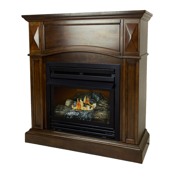
PRODUCT IDENTIFICATION VFF-PH(20NGB)(20NG)(20NG-C1)(20NG-2T1) VFF-PH(32NGB)(32NG)(32NG-H1)(32NG-2C1) VFF-PH(20LPB)(20LP)(20LP-C2)(20LP-2T2) VFF-PH(32LPB)(32LP)(32LP-H2)(32LP-2C2) VFF-PH(26NG)(26NG-T1)(26NG-2H1) VFF-PH(26LP)(26LP-T2)(26LP-2H2) Fireplace Fireplace Cabinet Cabinet Hood Hood Screen Screen Remote Transmitter Ignitor Button Ignitor Button Control Knob EI Receiver Control Knob Fig. 1 - Vent-Free Dual Fuel Fireplace Mantel Cabinet NOTE: The fireplace is installed into the mantel through the front opening of the mantel cabinet. WARNING: This fireplace is designed for use with the mantel cabinet provided. -
Page 7: Product Features
PRODUCT FEATURES SAFETY PILOT This heater has a pilot with an Oxygen Depletion Sensing (ODS) safety shutoff system. The ODS/pilot shuts off the heater if there is not enough fresh air and cuts off main burner gas in the event of flame out. ELECTRIC PUSH BUTTON IGNITION SYSTEM This heater is equipped with an electronic piezo control system. -
Page 8: Hood Assembly
HOOD ASSEMBLY (IF REQUIRED) WARNING: Always have screen in place before operating fireplace. This prevents excessive temperatures on fireplace surfaces. WARNING: Failure to position the parts in accordance with these diagrams or failure to use only parts specifically approved with this fireplace may result in property damage or personal injury. -
Page 9: Preparing For Installation
PREPARING FOR INSTALLATION AIR FOR COMBUSTION AND VENTILATION WARNING: This heater shall not be installed in a room or space unless the required volume of indoor combustion air is provided by the method described in the Nation Fuel Gas Code, ANSI Z223.1/NFPA 54, the International Fuel Gas Code, or applicable local codes. - Page 10 PREPARING FOR INSTALLATION DETERMINING FRESH-AIR FLOW FOR HEATER LOCATION Determining if You Have a Confined or Unconfined Space Use this worksheet to determine if you have a confined or unconfined space. Space: Includes the room in which you will install heater plus any adjoining rooms with doorless passageways or ventilation grills between the rooms.
- Page 11 PREPARING FOR INSTALLATION Ventilation Air From Inside Building This fresh air would come from adjoining unconfined space. When ventilating to an adjoining unconfined space, you must provide two permanent openings: one within 12 in. of the wall connecting the two spaces (see options 1 and 2, Fig.
-
Page 12: Installation
INSTALLATION NOTICE: This heater is intended for use as supplemental heat. Use this heater along with your primary heating system. Do not install this heater as your primary heat source. If you have a central heating system, you may run system’s circulating blower while using heater. This will help circulate the heat throughout the house. - Page 13 INSTALLATION FIREPLACE CLEARANCES CAUTION: If you install the fireplace in a home garage • fireplace pilot and burner must be at least 18" above floor. • locate fireplace where moving vehicle will not hit it. For convenience and efficiency, install fireplace •...
- Page 14 INSTALLATION WARNING: This optional blower is equipped with a three-prong (grounding) plug for your protection against shock hazard and must be plugged directly into a properly grounded three-prong receptacle. Firebox must be disconnected from gas supply and removed from mantel before installing fan accessory.
- Page 15 INSTALLATION Important: Insert the wires marked with AUTO, OFF and MAN into line slot on the right corner. Keep wires close to the bottom. Insert two wires’ female plugs marked with T1 and T2 (black and yellow) into two male ports on Temperature Sensor.
- Page 16 INSTALLATION Insert the blower link (male plug) into the power link (female port). Important: Bind wires with cable ties (G), and attach cable ties (G) in holes on back of Outer Casing. Attach one in hole near the top and one in hole near the bottom.
- Page 17 INSTALLATION Push Rocker Switch (E) into Control Panel and secure. Check that all wires are secure Green Ground Wire and reattach Blower Access Panel to Outer Casing. Capture the Screw Access Panel Green Ground wire between the Access Plate and Outer Casing Outer with the upper right screw.
- Page 18 INSTALLATION CONNECTING TO GAS SUPPLY WARNING: A qualified service technician must connect heater to gas supply. Follow all local codes. CAUTION: Never connect heater directly to the gas supply. This heater requires an external regulator (not supplied). The external regulator between the gas supply and heater must be installed. Gas supplier provides external regulator for natural gas.
- Page 19 INSTALLATION CAUTION: Use pipe joint sealant that is resistant to gas (PROPANE or NG). We recommend that you install a sediment trap in a supply line as shown in Fig. 10. Locate sediment trap where it is within reach for cleaning and not likely to freeze. Install in the piping system between fuel supply and heater.
- Page 20 ASSEMBLING LOGS VFF-PH(20NGB)(20NG)(20NG-C1)(20NG-2T1) VFF-PH(20LPB)(20LP)(20LP-C2)(20LP-2T2) VFF-PH(26NG)(26NG-T1)(26NG-2H1) VFF-PH(26LP)(26LP-T2)(26LP-2H2) WARNING: Failure to position the parts in accordance with these diagrams or failure to use only parts specifically approved with this heater may result in property damage or personal injury. CAUTION: After installation and peridically thereafter, check to ensure that no yellow flame comes in contact with any log.
- Page 21 ASSEMBLING LOGS VFF-PH(32NGB)(32NG)(32NG-H1)(32NG-2C1) VFF-PH(32LPB)(32LP)(32LP-H2)(32LP-2C2) WARNING: Failure to position the parts in accordance with these diagrams or failure to use only parts specifically approved with this heater may result in property damage or personal injury. CAUTION: After installation and peridically thereafter, check to ensure that no yellow flame comes in contact with any log.
- Page 22 INSTALLATION CHECKING GAS CONNECTIONS WARNING: Test all gas piping and connections for leaks after installing or servicing. Correct all leaks immediately. WARNING: Never use an open flame to check for a leak. Apply a mixture of liquid soap and water to all joints.
-
Page 23: Operation
OPERATION FOR YOUR SAFETY READ BEFORE LIGHTING WARNING: If you do not follow these instructions exactly, a fire or explosion may result causing property damage, personal injury or loss of life. A. This appliance has a pilot which must be lighted by the electronic ignitor. When lighting the pilot, follow these instructions exactly. - Page 24 OPERATION Models VFF-PH(32NGB)(32NG)(32NG-H1)(32NG-2C1) VFF-PH(32LPB)(32LP)(32LP-H2)(32LP-2C2) LEARN 1. STOP! Read the safety information on the page before this. 2. Open the lower access panel located below the fireplace screen. REMOTE • Set receiver switch to “ON” position (See Fig. 17). Fig. 17 - Receiver &...
-
Page 25: Remote Control Operation
REMOTE CONTROL OPERATION MULIT-FUNCTION WIRELESS REMOTE CONTROL SYSTEM FOR OPERATING A LATCHING SOLENOID VALVE, MANUALLY OR WITH A THERMOSTAT FUCTION IF YOU CANNOT READ OR UNDERSTAND THESE INSTALLATION INSTRUCTIONS DO NOT ATTEMPT TO INSTALL OR OPERATE INTRODUCTION This remote control system was developed to provide a safe, reliable, and user-friendly remote control system for gas heating appliances. - Page 26 REMOTE CONTROL OPERATION LCD - Liquid Crystal Display DISPLAY Indicates CURRENT room temperature . F OR Indicates degrees Fahrenheit or Celsius. FLAME Indicates burner/valve in operation. ROOM Indicates remote is in THERMO operation. TEMP Appears during manual operation. ROOM TEMP Appears during time the of setting the desired temperature in the thermo operation.
- Page 27 REMOTE CONTROL OPERATION release the SET key. The LCD screen will display the set temperature for 3 seconds and the LCD screen will flash the set temperature for 3 seconds, then the LCD screen will default to display the room temperature.
- Page 28 REMOTE CONTROL OPERATION FUNCTIONS: With the slide switch in the REMOTE position, the system will only operate Remote Receiver • if the remote receiver receives commands from the transmitter. Wire terminals Upon initial use or after an extended period of no use, the ON button may •...
- Page 29 REMOTE CONTROL OPERATION NOTE: Up to 6.3 VDC of power is provided at the receiver terminal. GENERAL INFORMATION COMMUNICATION – SAFETY – TRANSMITTER – (C/S – TX) This remote control has a COMMUNICATION –SAFETY function built into its software. It provides an extra margin of safety when the TRANSMITTER is out of the normal 20-foot operating range of the receiver.
- Page 30 REMOTE CONTROL OPERATION TRANSMITTER WALL CLIP The transmitter can be hung on a wall using the clip provided. If the clip is installed on a solid wood wall, drill 1/8" pilot holes and install with the screws WALL CLIP SLOT provided.
- Page 31 OPERATION INSPECTING BURNERS Check pilot flame pattern and burner flame patterns often. PILOT FLAME PATTERN Figure 20 shows a correct pilot flame pattern. Figure 21 shows an incorrect pilot flame pattern. The incorrect pilot flame is not touching the thermocouple. This will cause the thermocouple to cool. When the thermocouple cools, the fireplace will shut down.
-
Page 32: Care And Maintenance
CARE AND MAINTENANCE BURNER FLAME PATTERN Figure 22 shows a correct burner flame pattern. Figure 23 shows an incorrect burner flame pattern. The incorrect burner flame pattern shows sporadic, irregular flame tipping. The flame should not be dark or have an orange/reddish tinge. Note: When using the fireplace the first time, the flame will be orange for approximately one hour until the log cures. - Page 33 CARE AND MAINTENANCE 1. Shut off unit including pilot. Allow unit to cool for at least 30 minutes. 2. Inspect burner, pilot and primary air inlet holes on orifice holder for dust and dirt (See Fig. 24). 3. Blow air through the ports/slots and holes in the burner. 4.
-
Page 34: Troubleshooting
TROUBLESHOOTING WARNING: If you smell gas: • Shut off gas supply. • Do not try to light any appliance. • Do not touch any electrical switch; do not use any phone in your building. • Immediately call your gas supplier from a neighbor’s phone. Follow the gas supplier’s instructions. •... - Page 35 TROUBLESHOOTING PROBLEM POSSIBLE CAUSE CORRECTIVE ACTION 1. Control knob is not fully 1. Press in control knob fully. ODS/pilot lights but flame goes out pressed in. 2. Control knob is not pressed when control knob is 2. After ODS/pilot lights, keep control knob pressed in 30 seconds.
- Page 36 TROUBLESHOOTING PROBLEM POSSIBLE CAUSE CORRECTIVE ACTION 1. Turn heater off when using furniture White powder resi- 1. When heated, the vapors from furniture polish, wax, polish, wax, carpet cleaner or similar due forming within burner box or on carpet cleaners, etc., turn products.
-
Page 37: Replacement Parts
REPLACEMENT PARTS For replacement parts, call our customer service department at 1-877-447-4768, 8:30 a.m. – 4:30 p.m., CST, Monday – Friday. FIREBOX MODELS VFF-PH(20NGB)(20NG)(20NG-C1)(20NG-2T1), VFF-PH(20LPB)(20LP)(20LP-C2)(20LP-2T2), VFF-PH(26NG)(26NG-T1)(26NG-2H1) VFF-PH(26LP)(26LP-T2)(26LP-2H2), VFF-PH(32NGB)(32NG)(32NG-H1)(32NG-2C1), VFF-PH(32LPB)(32LP)(32LP-H2)(32LP-2C2) PART NUMBER ITEM DESCRIPTION VFF-PH20NG/LP Series VFF-PH26NG/LP Series VFF-PH32NG/LP Series Top Grille 700-S1014B 700-M1014B 700-L1014B... -
Page 38: Accessories
REPLACEMENT PARTS LIST For replacement parts, call our customer service department at 1-877-447-4768, 8:30 a.m. – 4:30 p.m., CST, Monday – Friday. VFF-PH(20NGB)(20NG)(20NG-C1)(20NG-2T1) VFF-PH(32NGB)(32NG)(32NG-H1)(32NG-2C1) VFF-PH(20LPB)(20LP)(20LP-C2)(20LP-2T2) VFF-PH(32LPB)(32LP)(32LP-H2)(32LP-2C2) VFF-PH(26NG)(26NG-T1)(26NG-2H1) VFF-PH(26LP)(26LP-T2)(26LP-2H2) ITEM PART NUMBER DESCRIPTION VFF-PH20NG/LP Series VFF-PH26NG/LP Series VFF-PH32NG/LP Series Log Set (complete) 700-S1018 700-M1018 700-L1018... - Page 40 This limited warranty is extended to the original retail purchaser of this heater and warrants against any years years...
- Page 41 GHP Group, Inc. 6440 W Howard S Niles, IL 60714-3302 Tel: (877) 447-4768 www.ghpgroupinc.com GHP Group, Inc. 6440 W Howard St Niles, IL 60714-3302...
- Page 42 CHIMENEA DE COMBUSTIBLE DUAL A GAS DE TIRO NATURAL Propano No. DE MODELO VFF-PH(20LPB)(20LP)(20LP-C2)(20LP-2T2) VFF-PH(26LP)(26LP-T2)(26LP-2H2) VFF-PH(32LPB)(32LP)(32LP-H2)(32LP-2C2) Gas Natural No. DE MODELO ADVERTENCIA: Este VFF-PH(20NGB)(20NG)(20NG-C1)(20NG-2T1) aparato está equipado para VFF-PH(26NG)(26NG-T1)(26NG-2H1) gas (Natural o Propano). La VFF-PH(32NGB)(32NG)(32NG-H1)(32NG-2C1) conversión de campo no está permitida.
- Page 44 TABLA DE CONTENIDO Epecificaciones............................... 2 Información de seguridad importante ......................3 Identificación del producto ..........................5 Características del producto ........................... 6 Desempaque ..............................6 Ensamblaje del extractor ..........................7 Preparación para la instalación ........................8 Instalación ..............................11 Operación ..............................23 Cuidado y mantenimiento ..........................
-
Page 45: Información De Seguridad Importante
INFORMACIÓN DE SEGURIDAD IMPORTANTE IMPORTANTE: Por favor, lea cuidadosa y completamente este manual del propietario antes de intentar ensamblar, operar o darle servicio a este calefactor. El uso inapropiado de este calefactor puede causar lesiones graves o la muerte por quemaduras, incendio, explosión, choque eléctrico y envenenamiento por monóxido de carbono. - Page 46 INFORMACIÓN DE SEGURIDAD 1. Este aparato es solo para ser usado con el tipo de gas indicado en la placa de características. Este aparato no es convertible para uso con otros gases. 2. No coloque el(los) tanque(s) de suministro de propano/PL dentro de ninguna estructura. Coloque el(los) tanque(s) de suministro de propano/PL en exteriores.
-
Page 47: Identificación Del Producto
IDENTIFICACIÓN DEL PRODUCTO VFF-PH(20NGB)(20NG)(20NG-C1)(20NG-2T1) VFF-PH(32NGB)(32NG)(32NG-H1)(32NG-2C1) VFF-PH(20LPB)(20LP)(20LP-C2)(20LP-2T2) VFF-PH(32LPB)(32LP)(32LP-H2)(32LP-2C2) VFF-PH(26NG)(26NG-T1)(26NG-2H1) VFF-PH(26LP)(26LP-T2)(26LP-2H2) Gabinete de Gabinete de chimenea chimenea Extractor Extractor Pantalla Pantalla Leño Transmisor remoto Leño Botón del Botón del encendedor encendedor Perilla de control Receptor EI Perilla de control Fig. 1 - Chimenea de combustible dual de tiro natural Gabinete del marco NOTA: La chimenea es instalada en la repisa de la chimenea a través de la abertura frontal de la... -
Page 48: Características Del Producto
CARACTERÍSTICAS DEL PRODUCTO PILOTO DE SEGURIDAD Este calefactor tiene un piloto con un sistema de apagado de seguridad de Detección de disminución de oxígeno (ODS). El ODS/piloto apaga el calefactor si no hay suficiente aire fresco y corta el gas del quemador principal en el caso de que la llama se apague. -
Page 49: Ensamblaje Del Extractor
ENSAMBLAJE DEL EXTRACTOR (SI SE REQUIERE) ADVERTENCIA: Tenga siempre la pantalla en su lugar antes de operar la chimenea. Esto evita temperaturas excesivas en las superficies de la chimenea. ADVERTENCIA: No colocar las piezas de acuerdo con estos diagramas o no usar solamente piezas específicamente aprobadas con esta chimenea puede resultar en daños a la propiadad o lesiones personales. -
Page 50: Preparación Para La Instalación
PREPARACIÓN PARA LA INSTALACIÓN AIRE PARA LA COMBUSTIÓN Y VENTILACIÓN ADVERTENCIA: Este calefactor no deberá ser instalado en una habitación o espacio a menos que el volumen requerido de aire de combustión de interiores sea proporcionado por el método descrito en el Código Nacional de Gas Combustible, ANSI Z223.1/NFPA 54, el Código Internacional de Gas Combustible, o códigos locales aplicables. - Page 51 PREPARACIÓN PARA LA INSTALACIÓN DETERMINACIÓN DEL FLUJO DE AIRE FRESCO A LA UBICACIÓN DEL CALEFACTOR Determinación de si tiene un espacio confinado o no confinado Use esta hoja de cálculo para determinar si tiene un espacio confinado o no confinado. Espacio: Incluye la habitación en la cual instalará...
- Page 52 PREPARACIÓN PARA LA INSTALACIÓN Aire de ventilación desde el interior del edificio Este aire fresco vendría del espacio no confinado contiguo. Cuando se ventila a un espacio no 12 pulg. confinado contiguo, debe proporcionar dos aberturas permanentes: una dentro de 12 pulg.
-
Page 53: Instalación
INSTALACIÓN AVISO: Este calefactor está diseñado para ser usado como calor complementario. Use este calefactor junto con su sistema de calefacción primario. No instale este calefactor como su fuente primaria de calor. Si tiene un sistema de calefacción central, puede poner a funcionar un soplador de circulación del sistema mientras usa el calefactor. - Page 54 INSTALACIÓN ESPACIOS LIBRES DE LA CHIMENEA PRECAUCIÓN: Si instala la chimenea en la cochera de su casa • el piloto y el quemador de la chimenea deben estar al menos a 18" sobre el piso. • coloque la chimenea donde vehículos en movimiento no la golpeen. Por conveniencia y eficiencia, instale la chimenea •...
- Page 55 INSTALACIÓN ADVERTENCIA: Este aparato está equipado con un enchufe de tres terminales (conexión a tierra) para su protección contra peligro de choque eléctrico y debe ser conectado directamente en un receptáculo de tres terminales con conexión a tierra apropiada. La caja de fuego debe ser desconectada del suministro de gas y retirada del marco antes de instalar los accesorios del ventilador.
- Page 56 INSTALACIÓN Importante: Inserte los cables marcados con AUTO, OFF y MAN en la ranura de línea en la esquina derecha. Mantenga los cables cerca del fondo. Inserte dos enchufes hembra de dos cables marcados con T1 y T2 (negro y amarillo) en dos puertos machos en el sensor de temperatura.
- Page 57 INSTALACIÓN Inserte el enlace del soplador (enchufe macho) en el enlace de energía (puerto hembra). Importante: Ate los cables con amarres de cable (G), y sujete los amarres de cable (G) en agujeros en la parte trasera de la cubierta exterior. Sujete uno en el agujero cercano a la cubierta y otro en el agujero cercano al fondo.
- Page 58 INSTALACIÓN Presione el interruptor oscilante (E) en el panel de control y asegure. Tierra verde Compruebe que todos los cables Cable estén seguros y reinstale el panel de acceso del soplador en la cubierta Tornillo Panel de acceso exterior. Atrape el el cable de tierra verde entre la la placa de acceso y la cubierta exterior con el tornillo Exterior...
- Page 59 INSTALACIÓN CONEXIÓN AL SUMINISTRO DE GAS ADVERTENCIA: Un técnico de servicio calificado debe conectar el calefactor al suministro de gas. Siga todos los códigos locales. PRECAUCIÓN: Nunca conecte el calefactor directamente al suministro de gas. Este calefactor requiere un regulador externo (no suministrado). El regulador externo entre el suministro de gas y el calefactor debe ser instalado.
- Page 60 INSTALACIÓN PRECAUCIÓN: Use sellador de juntas de tubo que sea resistente al gas (PROPANO O GN). Recomendamos una trampa de sedimentos en una línea de suministro como se muestra en la Fig. 10. Ubique la trampa de sedimentos donde esté al alcance para limpieza y que no existan probabilidades de que se congele. Instálela en el sistema de tuberías entre el suministro de combustible y el calefactor.
- Page 61 ENSAMBLAJE DE LOS LEÑOS VFF-PH(20NGB)(20NG)(20NG-C1)(20NG-2T1) VFF-PH(20LPB)(20LP)(20LP-C2)(20LP-2T2) VFF-PH(26NG)(26NG-T1)(26NG-2H1) VFF-PH(26LP)(26LP-T2)(26LP-2H2) ADVERTENCIA: No colocar las piezas de acuerdo con estos diagramas o no usar solamente piezas específicamente aprobadas con este calefactor puede resultar en daños a la propiadad o lesiones personales. PRECAUCIÓN: Después de la instalación y a partir de alli periódicamente, revise para asegurarse de que ninguna llama amarilla entre en contacto con los leños.
- Page 62 ENSAMBLAJE DE LOS LEÑOS VFF-PH(32NGB)(32NG)(32NG-H1)(32NG-2C1), VFF-PH(32LPB)(32LP)(32LP-H2)(32LP-2C2) ADVERTENCIA: No colocar las piezas de acuerdo con estos diagramas o no usar solamente piezas específicamente aprobadas con este calefactor puede resultar en daños a la propiadad o lesiones personales. PRECAUCIÓN: Después de la instalación y a partir de alli periódicamente, revise para asegurarse de que ninguna llama amarilla entre en contacto con los leños.
- Page 63 INSTALACIÓN REVISIÓN DE LAS CONEXIONES DE GAS ADVERTENCIA: Pruebe toda la tubería y conexiones de gas en contra de fugas después de la instalación y el servicio. Corrija todas las fugas de inmediato. ADVERTENCIA: Nunca use una llama abierta para revisar en busca de fugas. Aplique una mezcla de jabón líquido y agua en todas las juntas.
-
Page 64: Operación
OPERACIÓN PARA SU SEGURIDAD LEA ANTES DEL ENCENDIDO ADVERTENCIA: Si no sigue estas instrucciones exactamente, puede resultar un incendio o explosión ocasionando daños a la propiedad, lesiones personales o la muerte. A. Este aparato tiene una piloto que debe ser encendido por el encendedor electrónico. Cuando encienda el piloto, siga estas instrucciones exactamente. - Page 65 OPERACIÓN Modelos VFF-PH(32NGB)(32NG)(32NG-H1)(32NG-2C1) LEARN VFF-PH(32LPB)(32LP)(32LP-H2)(32LP-2C2) 1. ¡ALTO! Lea la información de seguridad a la izquierda de esta etiqueta. 2. Abra el panel de acceso inferior ubicado abajo de la pantalla de la chimenea. REMOTE • Coloque el interruptor del receptor en la posición “ON” (Ver Fig. 17). Fig.
- Page 66 OPERACIÓN DEL CONTROL REMOTO SISTEMA DE CONTRO - L REMOTO INALÁMBRICO MULTIFUNCIÓN PARA OPERAR UNA VÁLVULA SOLENOIDE DE ENGANCHE, MANUALMENTE O CON UNA FUNCIÓN DE TERMOSTATO. INTRODUCCIÓN Este sistema de control remoto fue desarrollado para brindar un sistema de control remoto seguro, confiable, y fácil de usar para aparatos de calefacción a gas.
- Page 67 OPERACIÓN DEL CONTROL REMOTO LCD - Pantalla de cristal líquido DISPLAY Indica la temperatura ambiente ACTUAL. Indica grados Fahrenheit o Celsius. FLAME Indica quemador/válvula en operación. ROOM Indica que el remoto está en operación TERMO. TEMP Aparece durante la operación manual. Aparece durante el tiempo del ajuste de la temperatura deseada en la operación termo.
- Page 68 OPERACIÓN DEL CONTROL REMOTO aumentarán de 45° a 99° luego se reinician a 45°) A continuación, suelte la tecla SET. La pantalla LCD mostrará la temperatura de ajuste durante 3 segundos y la pantalla LCD destellará la tempera- tura de ajuste durante 3 segundos, entonces la pantalla LCD mostrará...
- Page 69 OPERACIÓN DEL CONTROL REMOTO FUNCIONES: Receptor remoto Cuando el interruptor corredizo está en la posición REMOTE, el sistema solo funcionará si el receptor remoto recibe comandos del transmisor. Terminales de cable Luego del uso inicial o después de un periodo prolongado de no uso, es posible que el botón ON se tenga que presionar durante tres segundos antes Botón deslizante...
- Page 70 OPERACIÓN DEL CONTROL REMOTO INFORMACIÓN GENERAL COMUNICACIÓN – SEGURIDAD– TRANSMISOR – (C/S – TX) Este control remoto tiene una función de COMUNICACIÓN-SEGURIDAD incorporada en su software. Proporciona un margen extra de seguridad cuando el TRANSMISOR está fuera del rango de operación normal de 20 pies del receptor. La característica COMUNICACIÓN-SEGURIDAD opera en la manera siguiente, en todos los MODOS DE OPERACIÓN - ON/ ON THERMO.
- Page 71 OPERACIÓN DEL CONTROL REMOTO GANCHO DE PARED DEL TRANSMISOR El transmisor se puede colgar de la pared usando el gancho provisto. Si el gancho se instala en una pared sólida, perfore agujeros piloto de 1/8 pulg. e instalelo con los tornillos provistos. Si R A N U R A D EL está...
- Page 72 OPERACIÓN INSPECCIÓN DE LOS QUEMADORES Revise con frecuencia el patrón de la llama del piloto y los patrones de la llama del quemador. PATRÓN DE LA LLAMA DEL PILOTO La Figura 20 muestra un patrón correcto de la llama del piloto. La Figura 21 muestra un patrón incorrecto de la llama del piloto.
-
Page 73: Cuidado Y Mantenimiento
CUIDADO Y MANTENIMIENTO PATRÓN DE LA LLAMA DEL QUEMADOR La Figura 22 muestra un patrón correcto de la llama del quemador. La Figura 23 muestra un patrón incorrecto de la llama del quemador. El patrón incorrecto de la llama del quemador muestra puntas de llama esporádicas e irregulares. - Page 74 CUIDADO Y LIMPIEZA 1. Apague la unidad incluyendo el piloto. Deje que la unidad se enfríe durante 30 minutos. 2. Inspeccione el quemador, el piloto y los agujeros de entrada de aire primario en el porta orificio en busca de polvo y suciedad (Ver Fig. 24). 3.
-
Page 75: Resolución De Fallas
RESOLUCIÓN DE FALLAS ADVERTENCIA: Si huele gas: • Apague el suministro de gas • No trate de encender ningún aparato. • No toque ningún interruptor eléctrico; no use ningún teléfono en su edificio. • LLame de inmediato a su proveedor de gas del teléfono de un vecino. Siga las instrucciones del proveedor de gas. - Page 76 RESOLUCIÓN DE FALLAS PROBLEMA CAUSA POSIBLE ACCIÓN CORRECTIVA 1. La perilla de control no está El ODS/piloto enciende 1. Oprima por completo la perilla de control completamente presionada. pero la llama se apaga 2. La perilla de control no está cuando la perilla de 2.
- Page 77 RESOLUCIÓN DE FALLAS PROBLEMA CAUSA POSIBLE ACCIÓN CORRECTIVA Residuo de polvo blanco 1. Cuando se calientan, los vapores 1. Apague el calefactor cuando use que se forma dentro de del pulidor de muebles, cera, pulidor de mueble, cera, limpiador de alfombra o la caja del quemador o limpiadores de alfombra, ect.
-
Page 78: Piezas De Repuesto
PIEZAS DE REPUESTO Para piezas de repuesto, llame a nuestro departamento de servicio al cliente al 1-877-447-4768, de lunes a viernes, de 8:30 a.m. a 4:30 p.m., hora estándar del Centro. MODELOS DE CAJA DE FUEGO VFF-PH(20NGB)(20NG)(20NG-C1)(20NG-2T1), VFF-PH(20LPB)(20LP)(20LP-C2)(20LP-2T2), VFF-PH(26NG)(26NG-T1)(26NG-2H1), VFF-PH(26LP)(26LP-T2)(26LP-2H2), VFF-PH(32NGB)(32NG)(32NG-H1)(32NG-2C1), VFF-PH(32LPB)(32LP)(32LP-H2)(32LP-2C2) NÚM DE PIEZA NÚM DE... -
Page 79: Accesorios
LISTA DE PIEZAS DE REPUESTO Para piezas de repuesto, llame a nuestro departamento de servicio al cliente al 1-877-447-4768, de lunes a viernes, de 8:30 a.m. a 4:30 p.m., hora estándar del Centro. VFF-PH(20NGB)(20NG)(20NG-C1)(20NG-2T1) VFF-PH(32NGB)(32NG)(32NG-H1)(32NG-2C1) VFF-PH(20LPB)(20LP)(20LP-C2)(20LP-2T2) VFF-PH(32LPB)(32LP)(32LP-H2)(32LP-2C2) VFF-PH(26NG)(26NG-T1)(26NG-2H1) VFF-PH(26LP)(26LP-T2)(26LP-2H2) NÚM DE NÚM DE PIEZA DESCRIPCIÓN CANTIDAD... -
Page 81: Garantía
Garantía GARANTÍA LIMITADA: Esta garantía limitada se extiende al comprador original al por menor de este conjunto de calentador y garantiza contra cualquier defecto en materiales y mano de obra durante un periodo de (2) años a par tir de la fecha de venta al por menor. GHP Group, Inc., a su opción, proporcionará piezas de reemplazo o reparará... - Page 82 REGISTRO DE LA GARANTÍA IMPORTANTE: Le urgimos que llene su tarjeta de registro de la garantía en el plazo de catorce (14) después de la fecha de compra También puede registrar su garantíaen internet en www.ghpgroupinc.com. Complete el número de serie. Conserve esta porción de la tarjeta para sus registros.
Need help?
Do you have a question about the VFF-PH-PH20LPB and is the answer not in the manual?
Questions and answers
My pilot light keeps going out after a day or two.