Table of Contents
Advertisement
WARNING: This appliance
is equipped for (Natural and
Propane) gas. Field conversion
is not permitted other than
between natural or propane
gases.
CAUTION - FOR YOUR SAFETY
WARNING: IF THE INFORMATION IN THIS MANUAL IS NOT FOLLOWED
EXACTLY, A FIRE OR EXPLOSION MAY RESULT CAUSING PROPERTY
DAMAGE, PERSONAL INJURY OR LOSS OF LIFE.
WHAT TO DO IF YOU SMELL GAS
Questions, problems, missing parts? Before returning to your retailer, call our customer
service department at 1-877-447-4768, 8:00 a.m. – 4:30 p.m., CST, Monday – Friday or
email us at customerservice@ghpgroupinc.com.
INSTALLER: Leave this manual with the appliance.
CONSUMER: Retain this manual for future reference.
MODEL #VFF2-PH(20D)(20D-H)(20DB)(20D-C)(CPD-2T)
VFF2-PH(26D)(26DB)(26D-T)(IMD-2H)
VFF2-PH(32DR)(32DRB)(32DR-H)(FSDR-2C)
1
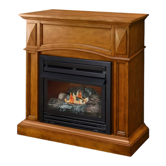
VENT-FREE GAS
DUAL FUEL FIREPLACE
Patent Pending Dual
Fuel System
NG
Dual Fuel
ANS Z21.11.2-2019
80-10-451 -
LP
2021-02-16
Advertisement
Table of Contents

Related Manuals for pleasant hearth VFF2-PH20/CP Series


Summary of Contents for pleasant hearth VFF2-PH20/CP Series
- Page 1 VENT-FREE GAS DUAL FUEL FIREPLACE MODEL #VFF2-PH(20D)(20D-H)(20DB)(20D-C)(CPD-2T) VFF2-PH(26D)(26DB)(26D-T)(IMD-2H) VFF2-PH(32DR)(32DRB)(32DR-H)(FSDR-2C) Patent Pending Dual Fuel System WARNING: This appliance is equipped for (Natural and Propane) gas. Field conversion is not permitted other than Dual Fuel between natural or propane gases. CAUTION - FOR YOUR SAFETY ANS Z21.11.2-2019 WARNING: IF THE INFORMATION IN THIS MANUAL IS NOT FOLLOWED EXACTLY, A FIRE OR EXPLOSION MAY RESULT CAUSING PROPERTY...
- Page 2 WARNING: WARNING:...
-
Page 3: Table Of Contents
TABLE OF CONTENTS ........................... 3 Important Safety Information ......................4 ........................6 Product Features ..........................7 Unpacking............................7 Hood Assembly..........................8 Preparing for Installation........................9 Installation ............................12 Operation............................24 Remote Control Operation.......................27 Care and Maintenance ........................33 Troubleshooting..........................36 Replacement Parts ......................... 38 Accessories ............................ -
Page 4: Important Safety Information
IMPORTANT SAFETY INFORMATION WARNING: FIRE, EXPLOSION, AND ASPHYXIATION HAZARD Improper adjustment, alteration, service, maintenance, or installation of this heater or its controls can cause death or serious injury. Read and follow instructions and precautions in User's Information Manual provided with this heater. IMPORTANT: Read this owner’s manual carefully and completely before trying to assemble, operate, explosion, electrical shock, and carbon monoxide poisoning. - Page 5 SAFETY INFORMATION 1. This appliance is only for use with the type of gas indicated on the rating plate. This appliance is not convertible for use with other gases. 2. Do not place propane/LP supply tank(s) inside any structure. Locate propane/LP supply tank(s) outdoors. 3.
- Page 6 PRODUCT IDENTIFICATION VFF2-PH(26D)(26DB)(26D-T)(IMD-2H) VFF2-PH(32DR)(32DRB)(32DR-H)(FSDR-2C) VFF2-PH(20D)(20DB)(20D-C)(CPD-2T) Fireplace Fireplace Cabinet Cabinet Hood Hood Screen Screen Remote Transmitter Ignitor Button Ignitor Button Control Knob EI Receiver Control Knob Fig. 1 - Vent-Free Dual Fuel Fireplace Mantel Cabinet WARNING:...
-
Page 7: Product Features
PRODUCT FEATURES SAFETY PILOT ELECTRIC PUSH BUTTON IGNITION SYSTEM This heater is equipped with an electronic push button control system. This system requires one AAA battery (provided). THERMOSTAT HEAT CONTROL temperature. See page 24. DUAL FUEL CAPABILITY Your heater is equipped to operate on either propane or natural gas. The heater is shipped from the factory ready for connecting to propane. -
Page 8: Hood Assembly
HOOD ASSEMBLY (IF REQUIRED) Tools Required: • Phillips screwdriver • scissors installation has been completed. 3. An optional blower is available. See Accessories, page 38. Install optional blower now. Follow installation instructions provided with blower. 4. Locate four black Phillips sheet metal screws in hardware packet. Louver Shoulder Screw Firebox Top... -
Page 9: Preparing For Installation
PREPARING FOR INSTALLATION WARNING: This heater shall not be installed in a room or space unless the required volume of indoor combustion air is provided by the method described in the Nation Fuel Gas Code, ANSI Z223.1/NFPA 54, the International Fuel Gas Code, or applicable local codes. 1. - Page 10 PREPARING FOR INSTALLATION Includes the room in which you will install heater plus any adjoining rooms with doorless passageways or ventilation grills between the rooms. 1. Determine the volume of the space Length × Width × Height = cu. ft. (volume of space) Example: Space size 20 ft.
- Page 11 PREPARING FOR INSTALLATION This fresh air would come from adjoining provide two permanent openings: one within 12 in. of the wall connecting the two spaces (see options 1 and 2, Fig. 4). You can also remove door into adjoining room (see option 3, Fig. 4). Follow the National Fuel Gas Code NFPA 54/ANS Z223.1.
-
Page 12: Installation
INSTALLATION NOTICE: This heater is intended for use as supplemental heat. Use this heater along with your primary heating system. Do not install this heater as your primary heat source. If you have a central heating system, you may run system’s circulating blower while using heater. This will help circulate the heat throughout the house. - Page 13 INSTALLATION FIREPLACE CLEARANCES • where there is easy access for operation, inspection and service • in coldest part of room • If this appliance is to be installed directly on carpeting, tile or other combsutible material, other than depth of the appliance. An optional blower kit is available from your retailer.
- Page 14 INSTALLATION WARNING: This optional blower is equipped with a three-prong (grounding) plug for your protection against shock hazard and must be plugged directly into a properly grounded three-prong receptacle. Firebox must be disconnected from gas supply and removed from mantel before Remove Blower Top Access Panel and Bottom Panel.
- Page 15 INSTALLATION Important: Insert the wires marked with AUTO, OFF and MAN into line slot on the right corner. Keep wires close to the bottom and guide to the front using the bottom access. Insert two wires’ female plugs marked with T1 and T2 (black and yellow) into two male ports on Temperature Sensor.
- Page 16 INSTALLATION Insert the blower link (male plug) into the power link (female port). : Bind wires with cable tie (G), and attach cable tie (G) side of the Outer Casing. Do the same with the wires through the bottom access panel. Keep wires from obstructing the blower.
- Page 17 INSTALLATION Push Rocker Switch (E) into Control Panel and secure. Secure the Green Ground wire to the Grounding screw hole from Screw the inside with the screw. Green Ground Wire Check that all wires are secure and reattach Blower Access Panel to Outer Casing.
- Page 18 INSTALLATION Electrical Wiring Diagram WHITE ~120V 60Hz GREEN BLACK AUTO OFF MAN 1. Power Cord 2. Bushing Strain Relief 3. Blower 4. Temperature Sensor 5. Rocker Switch NOTE: If any of the original wire as supplied with the appliance must be replaced, it must be replaced with a wire of at least an equal temperature rating.
- Page 19 INSTALLATION GAS SELECTION INSTRUCTIONS WARNING: This appliance can be used with propane or natural gas. It is shipped from the factory adjusted for use with propane. CAUTION: The knob to the gas selection means shall not be accessed or adjusted while the appli- ance is in operation.
- Page 20 INSTALLATION CONNECTING TO GAS SUPPLY WARNING codes. CAUTION: Never connect heater directly to the gas supply. This heater requires an external regulator (not supplied). The external regulator between the gas supply and heater must be installed. Gas supplier provides external regulator for natural gas. WARNING: Never connect heater to private (non-utility) gas wells.
- Page 21 INSTALLATION CAUTION: Use pipe joint sealant that is resistant to gas (PROPANE or NG). We recommend that you install a sediment trap in a supply line as shown in Fig. 10. Locate sediment trap where it is within reach for cleaning and not likely to freeze. Install in the piping system between fuel supply and heater.
- Page 22 ASSEMBLING LOGS WARNING: Failure to position the parts in accordance with these diagrams or failure to use only parts CAUTION: logs will create soot. Provided Logs: 5 It is very important to install the logs exactly as instructed. Do not modify logs. Use only logs supplied with heater.
- Page 23 ASSEMBLING LOGS WARNING: Failure to position the parts in accordance with these diagrams or failure to use only parts CAUTION: logs will create soot. Provided Logs: 5 It is very important to install the logs exactly as instructed. Do not modify logs. Use only logs supplied with heater.
- Page 24 INSTALLATION CHECKING GAS CONNECTIONS WARNING: Test all gas piping and connections for leaks after installing or servicing. Correct all leaks immediately. WARNING: to all joints. If bubbles form, there may be a leak. Correct all leaks immediately. from gas supply piping system. Pressures in excess of 1/2 PSIG will damage heater regulator. 3.
-
Page 25: Operation
OPERATION FOR YOUR SAFETY READ BEFORE LIGHTING A. This appliance has a pilot which must be lighted by the electronic ignitor. When lighting the pilot, follow these instructions exactly. B. BEFORE LIGHTING WHAT TO DO IF YOU SMELL GAS • Do not try to light any appliance. •... - Page 26 OPERATION LEARN 1. STOP! Read the safety information on the page before this. REMOTE • Set receiver switch to “ON” position (See Fig. 17). Fig. 17 - Receiver 3. Turn control knob clockwise to the “OFF” position (See Fig. 17). &...
-
Page 27: Remote Control Operation
REMOTE CONTROL OPERATION IF YOU CANNOT READ OR UNDERSTAND THESE INSTALLATION INSTRUCTIONS DO NOT ATTEMPT TO INSTALL OR OPERATE WALL CLIP SLOT BUTTON MODE BUTTON MODE BUTTON BUTTON BATTERY COMPARTMENT FRONT BACK MODE... - Page 28 REMOTE CONTROL OPERATION LCD - Liquid Crystal Display ROOM TEMP • TEMP TEMP TEMP TEMP ROOM TEMP...
- Page 29 REMOTE CONTROL OPERATION TEMP ROOM ROOM TEMP Requires 4-AA 1.5V alkaline batteries Learning button Slide Switch REMOTE Remote Receiver...
- Page 30 REMOTE CONTROL OPERATION • Remote Receiver Wire terminals • Receiver Slide Button LEARN • REMOTE • • • CORRECT WIRING PROCEDURES. IMPROPER INSTALLATION OF ELECTRIC COMPONENTS CAN Remote Receiver Wire terminals Receiver Slide Button LEARN REMOTE Pulse Connection Concentric Valve PULSE MODE Terminals Receiver...
- Page 31 REMOTE CONTROL OPERATION • • •...
- Page 32 REMOTE CONTROL OPERATION • • • • • • • FCC REQUIREMENTS AUTHORITY TO OPERATE THE EQUIPMENT.
- Page 33 OPERATION INSPECTING BURNERS PILOT FLAME PATTERN • see Troubleshooting, page 34. no yellow or orange color. Fig. 20 - Correct Pilot Flame Pattern Fig. 21 - Incorrect Pilot Flame Pattern LP PILOT LP PILOT NG PILOT NG PILOT WARNING: If yellow tipping occurs, your heater could produce increased levels of carbon page.
-
Page 34: Care And Maintenance
CARE AND MAINTENANCE BURNER FLAME PATTERN dark or have an orange/reddish tinge. the log cures. • see Troubleshooting, page 34. 6-12 inches above logs 2-3 inches above logs Fig. 22 - Correct Burner Flame Pattern Fig. 23 - Incorrect Burner Flame Pattern WARNING: CAUTION: You must keep control areas, burner, and circulating air passageways of heater... - Page 35 CARE AND MAINTENANCE 3. Blow air through the ports/slots and holes in the burner. of dust, dirt, lint or pet hair with a soft cloth or vacuum cleaner nozzle. 6. In case any large clumps of dust have now been pushed into the burner repeat steps 3 and 4. inlet hole.
-
Page 36: Troubleshooting
TROUBLESHOOTING WARNING: If you smell gas: • Do not try to light any appliance. • Do not touch any electrical switch; do not use any phone in your building. • Immediately call your gas supplier from a neighbor’s phone. Follow the gas supplier’s instructions. IMPORTANT: Operating heater where impurities in air exist may create odors. - Page 37 TROUBLESHOOTING 1. Control knob is not fully ODS/pilot lights 1. Press in control knob fully. pressed in. 2. Control knob is not pressed when control knob is 2. After ODS/pilot lights, keep control in long enough. released. knob pressed in 30 seconds. not fully open.
- Page 38 TROUBLESHOOTING White powder resi- 1. When heated, the vapors due forming within from furniture polish, wax, polish, wax, carpet cleaner or similar burner box or on carpet cleaners, etc., turn products. adjacent walls or into white powder residue. furniture. 1. Heater is burning vapors Heater produces 1.
-
Page 39: Replacement Parts
REPLACEMENT PARTS For replacement parts, call our customer service department at 1-877-447-4768, 8:30 a.m. – 4:30 p.m., CST, Monday – Friday. VFF2-PH(20D)(20DB)(20D-C)(CPD-2T), VFF2-PH(26D)(26DB)(26D-T)(IMD-2H), VFF2-PH(32DR)(32DRB)(32DR-H)(FSDR-2C) PART NUMBER ITEM DESCRIPTION VFF2-PH20/CP Series VFF2-PH26/IM Series VFF2-PH32/FS Series Top Grille 700-S1014B 700-M1014B 700-L1014B Hood... - Page 40 REPLACEMENT PARTS LIST For replacement parts, call our customer service department at 1-877-447-4768, 8:30 a.m. – 4:30 p.m., CST, Monday – Friday.
-
Page 41: Accessories
REPLACEMENT PARTS LIST PART NUMBER ITEM DESCRIPTION Log Set (Complete) 700-S1018 700-M1018 700-L1018 Log 1 700-S1018-01 700-M1018-01 700-L1018-01 Log 2 700-S1018-02 700-M1018-02 700-M1018-02 Log 3 700-S1018-03 700-M1018-03 700-M1018-03 Log 4 700-S1018-04 700-M1018-04 700-M1018-04 Log 5 700-S1018-05 700-M1018-05 700-M1018-05 Burner Assembly (Complete) 700-S2000 700-M2000 700-L2000... - Page 42 This limited warranty is extended to the original retail purchaser of this heater and warrants against any years years 42 33...
- Page 43 GHP Group, Inc. 6440 W Howard S Niles, IL 60714-3302 Tel: (877) 447-4768 www.ghpgroupinc.com GHP Group, Inc. 6440 W Howard St Niles, IL 60714-3302...
- Page 44 No. DE MODELO VFF2-PH(20D)(20D-H)(20DB)(20D-C)(CPD-2T) VFF2-PH(26D)(26DB)(26D-T)(IMD-2H) VFF2-PH(32DR)(32DRB)(32DR-H)(FSDR-2C) ANS Z21.11.2-2019 2021-02-16...
- Page 46 IMPORTANTE: Lea cuidadosamente todas las instrucciones y advertencias antes de comenzar la instalaci6n. No seguir estas instrucciones puede resultar en posibles lesiones a las personas o peligro de incendio y anulara la garantia. Modelo VFF2-PH20/CP Series VFF2-PH26/IM Series VFF2-PH32/FS Series Capacidad nom i nal de entrada...
Need help?
Do you have a question about the VFF2-PH20/CP Series and is the answer not in the manual?
Questions and answers