A.O. Smith 120 Series Installation Instructions Manual
Residential condensing gas water heaters
Hide thumbs
Also See for 120 Series:
- Service handbook (74 pages) ,
- Instruction manual (40 pages) ,
- Installation, user and service manual (104 pages)
Table of Contents
Advertisement
Quick Links
Installation Instructions, and
Use and Care Guide
RESIDENTIAL
CONDENSING GAS
WATER HEATERS
Power Vent / Power Direct Vent Gas Models
Not For Use in Manufactured (Mobile) Homes
⚠
WARNING
Safety Hazard
Improper installa�on, opera�on,
altera�on, or service might cause a
malfunc�on that results in property
damage, personal injury, or death.
Read and understand this instruc�on
manual and the safety messages
before installing, opera�ng, or
servicing this water heater.
This manual must remain with the
water heater.
Place these instructions adjacent to heater and notify owner to keep for future reference.
Keep this manual in the pocket on heater for future reference whenever maintenance adjustment or service is required.
PRINTED 1123
with Hot Surface Ignition
Series 120-121
WARNING: If the information in
these instructions is not followed
exactly, a fire or explosion may
result causing property damage,
personal injury, or death.
— Do not store or use gasoline or other
flammable vapors and liquids in the
vicinity of this or any other appliance.
— WHAT TO DO IF YOU SMELL GAS:
• Do not try to light any appliance.
• Do not touch any electrical switch;
do not use any phone in your
building.
• Immediately call your gas supplier
from a neighbor's phone. Follow the
gas supplier's instructions.
• If you cannot reach your gas
supplier, call the fire department.
— Installation and service must be
performed by a qualified installer,
service agency, or the gas supplier.
LOW LEAD
CONTENT
100368549_2000624920B
Advertisement
Table of Contents

Related Manuals for A.O. Smith 120 Series


Summary of Contents for A.O. Smith 120 Series
- Page 1 Installation Instructions, and Use and Care Guide RESIDENTIAL WARNING: If the information in these instructions is not followed CONDENSING GAS exactly, a fire or explosion may result causing property damage, WATER HEATERS personal injury, or death. — Do not store or use gasoline or other flammable vapors and liquids in the Power Vent / Power Direct Vent Gas Models vicinity of this or any other appliance.
-
Page 2: Table Of Contents
CONTENTS Water System Piping ...... 44 COMPLETED INSTALLATION (TYPICAL)..3 Installing the Exhaust/Condensate Tee .24 IMPORTANT SAFETY INFORMATION ....4 Important Notes and Warnings ....25 Electrical Connections ....44 Do Not Operate If Damaged ....4 Power Direct Venting (PDV) ....25 START UP AND OPERATIONS .......45 Hydrogen Gas Flammable .......4 Direct Vent Air Intake Moisture Start Up Conditions ......45... -
Page 3: Completed Installation (Typical)
COMPLETED INSTALLATION (TYPICAL) Vacuum Relief Valve Cold Water Line Water Shut Off Valve Hot Water Line Expansion Tank T&P Relief Valve Exhaust Vent Pipe Intake Air Connec�on Shut-Off Valve T&P Discharge Pipe Drain Pan Discharge Pipe Drain Pan Figure 1. Typical Installation Residential Condensing Gas Water Heaters •... -
Page 4: Important Safety Information
IMPORTANT SAFETY INFORMATION ⚠ DANGER To reduce the risk of property damage, serious escaping through the pipe as the water begins injury or death, read and follow the precautions to flow. THERE SHOULD BE NO SMOKING OR below, all labels on the water heater, and the OPEN FLAME NEAR THE FAUCET AT THE TIME Burn Hazard IT IS OPEN. -
Page 5: Warning Messages
IMPORTANT SAFETY INFORMATION WARNING MESSAGES Read and follow all safety messages and instructions in this manual. Important information to keep Related messages and instructions have been provided in this manual Fill out this section and keep this manual in the pocket of the and on your own water heater to warn you and others of a potential water heater for reference. -
Page 6: Risks During Installation And Maintenance
IMPORTANT SAFETY INFORMATION To reduce the risk of property damage, serious Table 1. Burn Time at Various ⚠ injury or death, read and follow the precautions WARNING Temperatures below, all labels on the water heater, and the Time for safety messages and instructions throughout Fire and Explosion Hazard Permanent this manual. -
Page 7: Water Contamination Risk
IMPORTANT SAFETY INFORMATION ⚠ ⚠ Water Contamination Risk WARNING WARNING ⚠ WARNING Burn Hazard Fire and Explosion Hazard Toxic Chemical Hazard Higher temperatures over 120°F Under certain condi�ons, the water (49°C) can cause severe burns heater can explode and catch fire, Connec�ng the water heater to a instantly resul�ng in severe injury or resul�ng in property damage,... -
Page 8: Carbon Monoxide Risk
IMPORTANT SAFETY INFORMATION ⚠ ⚠ A nationally recognized testing laboratory CAUTION WARNING maintains public inspection of the valve production process and certifies that it meets Property Damage Hazard Breathing Hazard-Carbon Monoxide Gas the requirements for Relief Valves for Hot Water An improperly installed or Improper installa�on use and Supply Systems, ANSI Z21.22. - Page 9 IMPORTANT SAFETY INFORMATION ⚠ CAUTION Property Damage Hazard Solvent cements and primers for plastic pipe are flammable liquids and emit flammable vapors. Improper use can cause an explosion and fire that would result in property damage. • Use only in well ventilated areas. •...
-
Page 10: Introduction
INTRODUCTION Thank You for purchasing this water heater. ANSI Z223.1 2006 Sec. 3.3.83: “Qualified water heaters. The qualified installer must also Properly installed and maintained, it should Agency” - “Any individual, firm, corporation be familiar with the design features and use give you years of trouble free service. -
Page 11: Preparing For Installation
INTRODUCTION See maintenance schedule in Maintenance PREPARING FOR INSTALLATION CSA International (page 50) and Troubleshooting (page 8501 East Pleasant Valley Road Read the entire manual before 54). By using the troubleshooting Cleveland, Ohio, United States attempting to install or operate the water checklist the user may be able to make 44131-5575 heater. -
Page 12: Massachusetts Installation Requirements
MASSACHUSETTS INSTALLATION REQUIREMENTS For all side wall terminated, horizontally vented the above requirements provided that during MANUFACTURER REQUIREMENTS - GAS power vent, direct vent, and power direct vent said thirty (30) day period, a battery operated EQUIPMENT VENTING SYSTEM PROVIDED gas fueled water heaters installed in every carbon monoxide detector with an alarm should W h e n t h e m a n u fa c t u re r o f P ro d u c t... -
Page 13: Features And Components
FEATURES AND COMPONENTS Termination Elbow With Vent Screen 16. *Metal Drain Pan 30. Temperature Sensor (included in Vent Kit) 17. *Ground Joint Union (Gas Connection) 31. Burner Insulation Shield *Vent Pipe 18. *Sediment Trap 32. Burner Refractory *Vent Pipe Elbow (Long Radius) 19. - Page 14 FEATURES AND COMPONENTS Figure 4. Blower and Intake Air Components for Natural Gas Figure 5. Blower and Intake Air Components for LP Gas 14 • Residential Condensing Gas Water Heaters...
-
Page 15: Model Characteristics
FEATURES AND COMPONENTS MODEL CHARACTERISTICS Table 2. Gas Pressure and Electrical Characteristics Minimum Maximum *Manifold Pressure Supply Pressure Supply Pressure Electrical Characteristics Gas Type In. W.C. (kPA) In. W.C.(kPA) In W.C.(kPA) Volts/Hz Amperes Natural 0” (0) 3.5(1.10) 14(3.49) 120/60 <5 Propane 0”(0) 8.0 (1.99) -
Page 16: Getting Started
GETTING STARTED BEFORE YOU BEGIN storage booster tank, your home and • Thread sealant tape or pipe joint other property, and can present risks of compound approved for potable serious injury or death. water. • For homes with copper pipes, you This water heater is designed as a may purchase a Gas Water Heater Category I, non-direct vented water... -
Page 17: Rough-In Dimensions
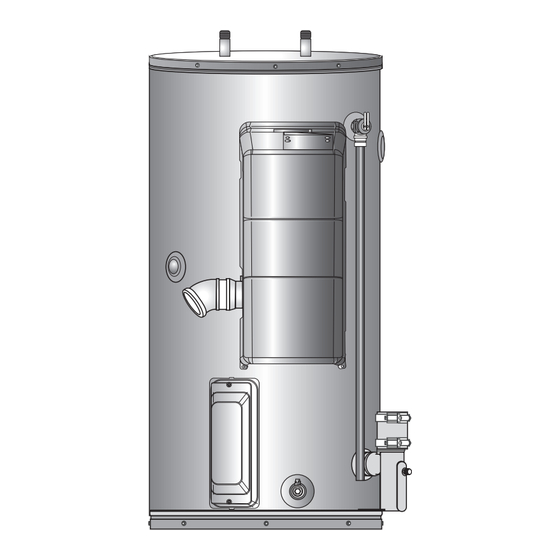
GETTING STARTED ROUGH-IN DIMENSIONS (Gas connection) Figure 10. Rough-In Front- and Right-Side Views Table 3. Rough-In Dimensions Key in Inches (centimeters) Models 45.00 (114.3) 22.38 (56.84) 15.75 (40) 10.5 (26.67) 27.75 (70.49) 8.75 (22.22) 22.00 (55.88) 8.00 (20.32) 40 Gallon 54.50 (138) 24.75 (62.86) 18.75 (47.62) -
Page 18: Verify That Your Home Is Equipped And Up-To-Date For Proper Operation
GETTING STARTED VERIFY THAT YOUR HOME IS EQUIPPED AND BACKGROUND: Over the years, many utilities As a result, most all plumbing systems today are UP-TO-DATE FOR PROPER OPERATION have increased water supply pressures so now “closed,” and almost all homes now need they can serve more homes. -
Page 19: Verify That The Location Is Appropriate
GETTING STARTED ⚠ ⚠ greater than diameter of heater. Pan WARNING CAUTION must not restrict combustion air flow. Burn Hazard Property Damage Hazard Locate the water heater close to the The temperature of the water in Over �me, the tank and fi�ngs of point of major hot water usage. -
Page 20: Removing The Old Water Heater
GETTING STARTED Do not locate water heater areas where Adequate clearance for inspection and service flammable liquids (vapors) are likely to be should be considered before installation. A present or stored (garages, storage and minimum of 24” of front clearance and 4” on utility areas, etc.): Flammable liquids (such as each side should be provided for access to gasoline, solvents, propane (LP or butane, etc.)) -
Page 21: Combustion Air And Ventilation
GETTING STARTED 12. Disconnect the water pipes. In many line that supplies the water heater. Install cases, the water pipes are connected the shut-off valve near the water heater 12” max. (30.5 cm) by a threaded union, which can be so that it is readily accessible. -
Page 22: Installing The Vent System
INSTALLING THE VENT SYSTEM PLANNING THE VENT SYSTEM Important: This water heater must be • Use long radius 45° and long radius 90° vented separately from all elbows wherever possible. This water heater may be installed in either other appliances. DO NOT •... -
Page 23: Vent Pipe Material
INSTALLING THE VENT SYSTEM Note: The Condensate/Exhaust tee and outlet Important: Use only solid (not foam core) pressure switch tubing will need to be piping. Plastic pipe and fittings connected to the water heater before are available through most the exhaust venting can be connected plumbing suppliers. -
Page 24: Vent Pipe Runs
INSTALLING THE VENT SYSTEM Do not seal the vent piping to the wall Table 7. Pressure Switch Settings until the venting is properly connected to Pressure Switch the condensate trap assembly. Setting (NC) Nat Gas LP Gas Complete the venting installation by Outlet Air (OAPS) 1.8”... -
Page 25: Important Notes And Warnings
INSTALLING THE VENT SYSTEM Switch or the OAPS will not function POWER DIRECT VENTING (PDV) DIRECT VENT AIR INTAKE MOISTURE PRO- TECTION properly. The combustion air intake and exhaust vent The air intake piping in a direct vent system will system and termination may be installed in one normally not have any moisture accumulation in of the following type terminations:... -
Page 26: Termination Clearances Sidewall Power Vent
INSTALLING THE VENT SYSTEM TERMINATION CLEARANCES SIDEWALL POWER VENT Inside corner detail 15 ft Fixed closed Operable Fixed Closed Operable Regulator vent outlet In the event no regulator is present, Legend: H and I can be = Area where terminal is not permitted = Vent terminal = Air supply inlet disregarded... -
Page 27: Side Wall Vent Termination (Standard)
INSTALLING THE VENT SYSTEM vent length. See Table 6 (page SIDE WALL VENT TERMINATION (STANDARD) The air intake termination and the exhaust vent termination shall extend 23). Important: When terminating the vent 12” above anticipated snow level and at on a side wall, the following 8 inches MIN. -
Page 28: Multiple Concentric Vent Termination
INSTALLING THE VENT SYSTEM When more than 2 kits are installed only 2 of them shall be less than 9.5” apart. Never install 3 termination kits together less than 9.5” apart (see Figure 35). Wall Combustion Above Anticipated Snow 9.5 inches (24 cm ) maximum or Level or 18”... -
Page 29: Low Profile Vent Installation
INSTALLING THE VENT SYSTEM LOW PROFILE VENT INSTALLATION properly connected to concentric vent termination This water heater is certified for sidewall direct Air Inlet venting with IPEX System 636 Low Profile Piping Vent Kit. Follow instructions below for proper installations. Vent Base All termination kits must be located and installed in accordance with local building... -
Page 30: Calculating Equivalent Feet (Pdv)
INSTALLING THE VENT SYSTEM CALCULATING EQUIVALENT FEET (PDV) Table 11. Calculating Equivalent Feet (PDV) Water Heater Vent Size Pressure Switch Settings (in. w.c.) 2 Pipe Equiv. Vent Length Conc. Vent Equiv. Vent Length Heater Input (Inside Model (Btu/Hr) Diam.) Intake (Nat/LP) Exhaust (Nat/LP) Max. -
Page 31: Installing A New Tee Termination
INSTALLING THE VENT SYSTEM INSTALLING A NEW TEE TERMINATION INSTALLING A NEW 90° TERMINATION 18” Vent Screen (457 mm) Apply sealant Install in to both sides termination. A tee fitting, purchased separately, as the A 90° elbow, purchased separately, as the of wall. -
Page 32: Termination Clearances Other Than Sidewall Direct Vent
INSTALLING THE VENT SYSTEM TERMINATION CLEARANCES OTHER THAN SIDEWALL DIRECT VENT Inside corner detail 15 ft Fixed closed Operable Fixed Closed Operable Regulator vent outlet In the event no regulator is present, Legend: H and I can be = Area where terminal is not permitted = Vent terminal = Air supply inlet disregarded... - Page 33 INSTALLING THE VENT SYSTEM 6” (150 mm) Attach Sealant termination elbow. Debris Screen Vent Pipe to be (Install into Cover Plate 12” sloped (down) toward Elbow) (300 mm) (optional) heater to prevent min.* water from collecting. Ground May require a Sealant Level* condensate tee.
-
Page 34: Calculating Equivalent Feet (Pv)
INSTALLING THE VENT SYSTEM CALCULATING EQUIVALENT FEET (PV) Table 14. Calculating Equivalent Feet (PV) Water Pressure Switch Settings (in. w.c.) Heater Heater Input Vent Size Max. Equivalent Vent Min. Equivalent Vent Model (Btu/Hr) (Inside Diam.) Intake (Nat/LP) Exhaust (Nat/LP) Length Length 40 gal. -
Page 35: Installing The Water Heater
INSTALLING THE WATER HEATER THERMOSTATIC POINT-OF-USE MIXING DO NOT install any external condensate trap. Water heated to a temperature which satisfies VALVES The exhaust tee assembly has an internal space heating, clothes washing, dish washing, ⚠ condensate trap built in. and other sanitizing needs can scald and cause CAUTION permanent injury upon contact. -
Page 36: Closed Water Systems
INSTALLING THE WATER HEATER CLOSED WATER SYSTEMS Do not apply heat to the cold water inlet. Table 15. Burn Time at Various Temperatures Note: To protect against untimely corrosion of Water supply systems may, because of code Time for Per- hot and cold water fittings, it is strongly manent Burns requirements or such conditions as high line... -
Page 37: Temperature-Pressure Relief Valve
INSTALLING THE WATER HEATER ⚠ Note: If using copper tubing, solder tubing to T&P Valve Discharge Pipe CAUTION ⚠ an adapter before attaching the adapter CAUTION to the water heater connections. Do Property Damage Hazard not solder the water lines directly to Property Damage Hazard the water heater connections. -
Page 38: Space Heating Applications
INSTALLING THE WATER HEATER Temperature Regulation (page 47). Water SPACE HEATING APPLICATIONS Your water heater is equipped with Combo piping and vent piping occupy the space above Heating capabilities and are shipped with the two side plumbing taps PLUGGED (items 24 and the water heater. -
Page 39: Combo Heating Installation
INSTALLING THE WATER HEATER See also Massachusetts Installation Requirements “Combo” Heating Systems require be drained from the heating module higher water temperatures than without affecting the water heater. (page 12). other applications. When the system HOT WATER EXPANSION TANK (OPTIONAL) If the air handler does not have a venting is used to supply water for Combo TO HOUSE... -
Page 40: Electrical Wiring
INSTALLING THE WATER HEATER Electrical Wiring Note: The wiring diagram can be found in • The electrical outlet has the proper Diagrams (page 58). Always reference overload fuse or breaker protection. If you lack the necessary skills required to the wiring diagram(s) for the correct The unit must be connected to a 120 properly install the electrical wiring to this electrical connections. -
Page 41: Gas Line Installation
INSTALLING THE WATER HEATER ⚠ ⚠ and no farther than 8’ from the water WARNING WARNING heater’s inlet gas connection. Fire and Explosion Hazard Fire and Explosion Hazard After installing the positive lock-up gas Contaminants in gas lines can cause pressure regulator(s) an initial nominal Under certain circumstances, the fire or explosion. -
Page 42: Gas Line Sizing
INSTALLING THE WATER HEATER Note: Always secure the square on the gas valve base with a suitable wrench when tightening or loosening the gas piping. Gas Control Valve Sediment Trap Ground Joint Union (op�onal) Figure 53. Black Pipe to Gas Valve Gas Line Sizing The values given in Table 16 and Table 17 are for Depending on the developed equivalent length... -
Page 43: Gas Supply Line Leak Testing
INSTALLING THE WATER HEATER ⚠ WARNING Table 17. Supply Gas Line Sizing Metric Units Normal Iron Pipe Sizes (inches) Breathing Hazard Input in kW Length In Breathing carbon monoxide can Meters 1/2” 3/4” 1” 1 1/4” 1 1/2” 2” cause brain damage or death. 1160 Do the following to avoid carbon monoxide poisoning:... -
Page 44: Installation Checklist
INSTALLING THE WATER HEATER plumbing supplier). Dielectric unions installation area is subject to freezing home’s water pressure is above 80 psi. temperatures. Insulating the hot water can help prevent corrosion caused by pipes can increase energy efficiency. tiny electric currents common in copper water pipes and can help extend the life Adjust (or install) the home’s Pressure of the water heater. -
Page 45: Start Up And Operations
START UP AND OPERATIONS START UP CONDITIONS Before attempting start up, thoroughly study hot water faucet. Allow water to run ⚠ and familiarize yourself with the exact sequence until a constant flow is obtained. This CAUTION of operation. See Basic Sequence Of Operation will let air out of the water heater and (page 55), Burner Ignition Sequence (page piping. -
Page 46: Lighting The Water Heater
TIME TO PRODUCE THERMOSTAT – DÉLAI D’ÉBOUILLANTAGE TEMPERATURE VOIR LE MANUEL (BRÛLURE AU 2 ET 3 DEGRÉ 2nd & 3rd DEGREE SETTING, SEE D’INSTRUCTIONS SUR LA PEAU D’UN ADULTE) BURNS ON ADULT SKIN INSTRUCTION MANUAL 160°F (71°C) ABOUT 1/2 SECOND 160°F (71°C) ENVIRON 0,5 SECONDE 150°F (65°C) -
Page 47: Temperature Regulation
TEMPERATURE REGULATION TEMPERATURE CONTROL Install Thermostatic Mixing Valves to regulate or death. The temperature at which injury ⚠ the temperature of the water supplied to occurs varies with the person’s age and time DANGER each point-of-use (for example, kitchen sink, of the exposure. -
Page 48: High Temperature Applications
TEMPERATURE REGULATION settings at specific lower temperatures. Check support phone number listed on front page of Table 18. Burn Time at Various with the code authority having jurisdiction. this manual for further technical assistance. Temperatures Time for The water heaters covered in this manual are HIGH TEMPERATURE LIMIT CONTROL (ECO) Permanent equipped with an electronic control system to... -
Page 49: Control System Operation
CONTROL SYSTEM OPERATION SWITCHING BETWEEN TEMPERATURE UNITS When the heater is ON, the ON/OFF icon is not ON/OFF ON/OFF LOCK FLAME ON CELSIUS PLUS shown. Setpoint/Error codes are shown on LCD. To switch temperature units (°F/°C), unlock the Lock/Unlock, °C, °F, flame, service and warning ON/OFF control and press button and the... -
Page 50: Maintenance
MAINTENANCE ⚠ DANGER Table 19. Maintenance Schedule Burn Hazard Component Operation Interval Reference See Draining and Flushing. The discharge from the Tank Drain and Flush Every 6 Months Lime Scale Removal temperature-pressure relief valve Tank (Water Less Than 25 Not Required can be hot enough to burn. -
Page 51: Sediment Removal
MAINTENANCE Flush the water heater storage tank to escape when heated. Lime scale accumulation You should also check for sooting. Soot is not remove sediment and allow the water to also reduces the life span of water heaters. For normal and will impair proper combustion. A flow until it runs clean. -
Page 52: Housekeeping
MAINTENANCE HOUSEKEEPING Certain water conditions will cause a reaction TEMPERATURE-PRESSURE RELIEF VALVE ⚠ TEST between the anode rod and the water. The most WARNING common complaint associated with the anode It is recommended that the Temperature- rod is a “rotten egg smell” produced from the Fire and Explosion Hazard Pressure Relief Valve be checked every 6 months presence of hydrogen sulfide gas dissolved... -
Page 53: Service
MAINTENANCE Valve is not intended for the constant relief of thermal expansion. Temperature-Pressure Relief Valve leakage due to pressure build up in a closed system that does not have a thermal expansion tank installed is not covered under the limited warranty. Thermal expansion tanks must be installed on all closed water systems. -
Page 54: Troubleshooting
TROUBLESHOOTING SERVICE MODE Example: mode and no button is pressed for 30 seconds, the unit will go back to operation mode, with To enter in the service mode, unlock the buttons H06-5.00 is the service code for “H06 Blower the setpoint on the display and the buttons by simultaneously pressing the “Lock/Unlock”... -
Page 55: Basic Sequence Of Operation
TROUBLESHOOTING BASIC SEQUENCE OF OPERATION for 3 times in less than five minutes the heater Function is automatically enabled. Errors E10, will go in error mode (E03 lose flame 3 times in 5 E11, and buzzer will be enabled as well. With Call for Heat: minutes). -
Page 56: Clearing Error Codes
TROUBLESHOOTING CLEARING ERROR CODES Soft faults are also automatically cleared after 15 minutes after the fault condition occurred, Hard Faults and Soft Faults can be cleared if the conditions of the faults disappeared. If following two steps: the fault condition is still set, the control will attempt to clear the Soft Faults after another Unlock the control (by pressing the 15 minutes (and so on). -
Page 57: Error Priority
TROUBLESHOOTING Error Priority CHECKING FOR LEAKS A. *Condensation may be seen on the hot water outlet pipe in humid weather or the If multiple error conditions arise at the same hot water outlet connection may be leaking. time, the Control will always give priority to hard faults over soft faults, and to soft faults B. -
Page 58: Diagrams
DIAGRAMS WIRING DIAGRAM (Optional - External) Outdoor Water Temp Flame AC Power Shutoff Valve Sensor 120 Vac Diagnostic Port NTC1 NTC2 OAPS IAPS Blower Gas Valves Figure 62. Wiring Diagram 58 • Residential Condensing Gas Water Heaters... -
Page 59: Service Parts List
SERVICE PARTS LIST Table 24. Service Parts List Kit Number Description 100344160 K,SIT BLOWER/GAS CONTROL VALVE,NG,0480.408 (Natural Gas Models Only) 100344191 K, IGNITER SIDEFIRE 100344192 K,FLAME SENSOR BENT 100344193 K,BURNER,4.5",STAINLESS STEEL,NG (Natural Gas Models Only) 100344194 K,GASKET,BURNER,1/2" THK 100368397 K,CONTROL BOARD,NG,50K (Natural Gas Models Only) 100368398 K,CONTROL BOARD,NG,65K (Natural Gas Models Only) 100344198... - Page 60 500 Tennessee Waltz Parkway, Ashland City, TN 37015 • Technical Support: 800-527-1953 • Parts: 800-433-2545 • Fax: 800-644-9306 www.hotwater.com Copyright © 2023 A. O. Smith Corporation. All rights reserved.
Need help?
Do you have a question about the 120 Series and is the answer not in the manual?
Questions and answers