A.O. Smith 120 Series Instruction Manual
Residential gas water heaters
Hide thumbs
Also See for 120 Series:
- Service handbook (74 pages) ,
- Installation instructions manual (60 pages) ,
- Instruction manual (120 pages)
Table of Contents
Advertisement
Quick Links
ALL TECHNICAL AND WARRANTY QUESTIONS: SHOULD BE DIRECTED TO THE LOCAL DEALER FROM WHOM THE WATER HEATER WAS
PURCHASED. IF YOU ARE UNSUCCESSFUL, PLEASE WRITE TO THE COMPANY LISTED ON THE RATING PLATE ON THE WATER HEATER.
PRINTED 0517
RESIDENTIAL GAS WATER HEATERS
LOW LEAD
CONTENT
KEEP THIS MANUAL IN THE POCKET ON HEATER FOR FUTURE REFERENCE
WHENEVER MAINTENANCE ADJUSTMENT OR SERVICE IS REQUIRED.
POWER VENTED GAS MODELS W/HOT SURFACE IGNITION
NOT FOR USE IN MANUFACTURED (MOBILE) HOMES
•
AN ODORANT IS ADDED TO THE GAS USED
1
Instruction Manual
120 SERIES MODELS
For Your Safety
BY THIS WATER HEATER.
100282882_2000542152_Rev. C
•
Advertisement
Table of Contents

Related Manuals for A.O. Smith 120 Series


Summary of Contents for A.O. Smith 120 Series
- Page 1 Instruction Manual RESIDENTIAL GAS WATER HEATERS POWER VENTED GAS MODELS W/HOT SURFACE IGNITION NOT FOR USE IN MANUFACTURED (MOBILE) HOMES 120 SERIES MODELS LOW LEAD CONTENT • • For Your Safety AN ODORANT IS ADDED TO THE GAS USED BY THIS WATER HEATER.
-
Page 2: Safe Installation, Use And Service
SAFE INSTALLATION, USE AND SERVICE The proper installation, use and servicing of this water heater is extremely important to your safety and the safety of others. Many safety-related messages and instructions have been provided in this manual and on your own water heater to warn you and others of a potential injury hazard. -
Page 3: General Safety Information
GENERAL SAFETY INFORMATION Fire Hazard For continued protection against risk of f ire: • Do not install water heater on carpeted floor. • Do not operate water heater if any part has been exposed to flooding or water damage. - Page 4 GENERAL SAFETY INFORMATION CAUTION Improper installation, use and service may result in property damage. • Do not operate water heater if any part has been exposed to flooding or water damage. • Inspect anode rods regularly, replace if damaged. • Install in location with drainage.
-
Page 5: Table Of Contents
TABLE OF CONTENTS SAFE INSTALLATION, USE AND SERVICE..........2 Sediment Traps .................. 17 APPROVALS ....................2 Filling the Water Heater ..............17-18 GENERAL SAFETY INFORMATION ............3-4 Vent Pipe Assembly ................18 TABLE OF CONTENTS ................5 Venting ....................18 INTRODUCTION ..................5 Vent Pipe Termination ................ -
Page 6: Installation Requirements For The Commonwealth Of Massachusetts
INSTALLATION REQUIREMENTS FOR THE COMMONWEALTH OF MASSACHUSETTS COMMONWEALTH OF MASSACHUSETTS INSPECTION The state or local gas inspector of the side wall horizontally For all side wall terminated, horizontally vented power vent, direct vented gas fueled equipment shall not approve the installation vent, and power direct vent gas fueled water heaters installed in unless, upon inspection, the inspector observes carbon monoxide every dwelling, building or structure used in whole or in part for... -
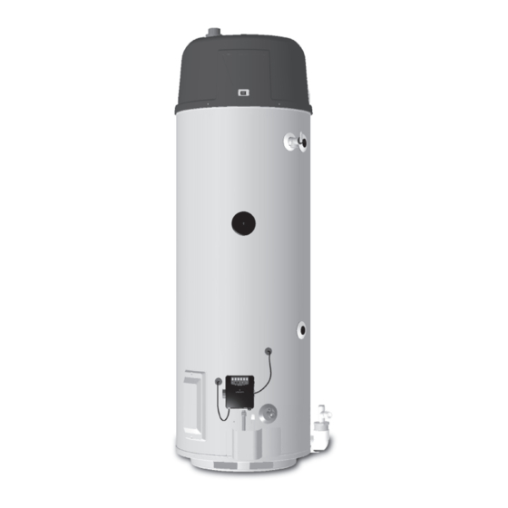
Page 7: Typical Installation
TYPICAL INSTALLATION GET TO KNOW YOUR WATER HEATER - GAS MODELS A Vent Pipe Q Rating Plate El b ow B Anode Bushing R Insulation C Hot Water Outlet Nipple Vent Terminal D Outlet (120 VAC) Condensate Tee Drain Valve F Gas Supply Igniter And Main Burner Adapter... - Page 8 TYPICAL INSTALLATION CONDENSATE HOSE AND DRAIN PAN FIGURE 1 (continued).
-
Page 9: Mixing Valves
TYPICAL INSTALLATION MIXING VALVE / THERMAL EXPANSION TANK USAGE AND SPACE HEATING FIGURE 2. MIXING VALVES Mixing valves are available at plumbing supply stores. Consult a Qualified Installer or Service Agency. Follow mixing valve manufacturer’s instructions for installation of the valves. DANGER Water temperature over 125°F (52°C) TABLE 1. -
Page 10: Locating The New Water Heater
LOCATING THE NEW WATER HEATER FACTS TO CONSIDER ABOUT THE LOCATION Carefully choose an indoor location for the new water heater, because the placement is a very important consideration for the safety of the occupants in the building and for the most economical use of the appliance. -
Page 11: Insulation Blankets
in an alcove or closet, the entire floor must be covered by the panel. If this water heater will be used in beauty shops, barber shops, cleaning establishments, or self-service laundries with dry cleaning Failure to heed this warning may result in a fire hazard. equipment, it is imperative that the water heater or water heaters be installed so that combustion and ventilation air be taken from outside these areas. -
Page 12: Unconfined Space
Such a condition often will result in a yellow, luminous burner free area and metal louvers and grilles will have 75% free area. Non flame, causing sooting of the combustion chamber, burners and motorized louvers and grilles should be fixed in the open position. flue tubes and creates a risk of asphyxiation. -
Page 13: Outdoor Air Through Two Horizontal Ducts
Figure 7. The water heater should have clearances of at least 1 inch The confined space should be provided with two permanent vertical (25 mm) from the sides and back and 6 inches (150 mm) from the front ducts, one commencing within 12 inches (300 mm) of the top and of the appliance. -
Page 14: Installing The New Water Heater
INSTALLING THE NEW WATER HEATER This water heater should not be connected to any heating systems CHEMICAL VAPOR CORROSION or component(s) used with a non-potable water heating appliance. CORROSION OF THE FLUEWAYS AND VENT SYSTEM MAY All piping components connected to this unit for space heating OCCUR IF AIR FOR COMBUSTION CONTAINS CERTAIN CHEMICAL applications should be suitable for use with potable water. -
Page 15: Thermal Expansion
THERMAL EXPANSION duct tape, electrical tape, or equivalent. IMPORTANT: The insulation and tape must not block the discharge opening or hinder access to the As water is heated, it expands (thermal expansion). In a closed system manual relief lever (Figure 11). Ensure a discharge pipe is installed into the volume of water will grow when it is heated. -
Page 16: High Altitude Installation
HIGH ALTITUDE INSTALLATION discharge opening must not be blocked or reduced in size under any circumstances. Excessive length, over 30 feet (9.14 m), or use of more than four elbows can cause restriction and reduce the discharge capacity of the valve. No valve or other obstruction is to be placed between the Temperature-Pressure Relief Valve and the tank. -
Page 17: Sediment Traps
SEDIMENT TRAPS A gas line of sufficient size must be run to the water heater. Consult the current edition of National Fuel Gas Code (ANSI Z223.1/NFPA 54) and your gas supplier concerning pipe size. There must be: • A readily accessible manual shuttoff valve in the gas supply line serving the water heater, and •... -
Page 18: Vent Pipe Assembly
Never use this water heater unless it is completely full of water. To prevent see Figure 16. Disassemble the parts and cement back together damage to the tank, the tank must be filled with water. Water must flow using the alignment marks. After the cement dries, attach the from the hot water faucet before turning “ON”... -
Page 19: Vent Pipe Termination
TERMINATION CLEARANCES SIDEWALL POWER VENT FIGURE 15. Vent terminal clearances for “Power Vent” installations. Power Vent configurations use room air for combustion. US INSTALLATIONS US INSTALLATIONS Clearance to each side of center Clearance in accordance with Clearance above grade, veranda, 12 inches (30 cm) line extended above meter/regulator local installation codes and the... -
Page 20: Planning The Vent System
PLANNING THE VENT SYSTEM diameter. An appropriately sized 45 degree schedule 40 DWV elbow (field supplied) vent terminal must be obtained with an Plan the route of the vent system from the discharge of the blower equivalent screen (supplied in the vent kit). The total system to the planned location of the vent terminal. -
Page 21: Polypropylene Installations
in system. If any of these conditions are found, they must be assembly #1. As with every water heater installation, a drain pan corrected in accordance with venting instructions in this manual should be used to prevent water damage to surrounding area. If before completing installation and putting water heater into service. -
Page 22: Blower Assembly Installation
Condensate is likely to form in the venting system attached to this 8. Do not plug in power cord until vent system is completely installed. water heater. The vent pipe should be sloped downward away from The Power Vent operates on 110-120 Vac. therefore a grounded the blower assembly (not less than 1/8”... - Page 23 holes by drilling a hole through center of the template from the bead of caulking (not supplied) around the gap between the pipe and inside through to the outside. The template can now be positioned cover plate. Apply enough to fill some of the gap between the pipe and wall.
-
Page 24: Installation Of Vent System, Sidewall
INSTALLATION OF VENT SYSTEM, SIDEWALL additional vent pipe when calculating maximum equivalent feet of venting. With the route of the venting system and selection of materials completed, as discussed in the section of this manual titled PLANNING THE VENT INSTALLATION OF VERTICAL VENT SYSTEM SYSTEM, the through the wall vent terminal in place and the first section of piping, up to first elbow, installed at the blower it is time to complete the A proper flashing or “BOOT”... -
Page 25: Vent Pipe Preparation
VENT PIPE PREPARATION PRIMER It is recommended that Tetrahydrofuran (THF) be used to prepare the 1. INITIAL PREPARATION surfaces of pipe and fittings for solvent welding. Do not use water, rags, gasoline or any other substitutes for cleaning PVC or CPVC Make sure the solvent cement you are planning to use is surfaces. - Page 26 B. Deburring Use a knife, plastic pipe deburring tool, or file to remove burrs from the end of small diameter pipe. Be sure to remove all burrs from around the inside as well as the outside of the pipe. A slight chamfer (bevel) of about 10°-15°...
-
Page 27: Lighting & Operating Label
FOR YOUR SAFETY READ BEFORE LIGHTING f i l A. This appliance does not have a pilot. It is equipped with If you cannot reach your gas supplier, call the fire an ignition device which automatically lights the burner. department. Do not try to light the burner by hand. -
Page 28: Temperature Regulation
TEMPERATURE REGULATION To avoid any unintentional changes in water temperature settings, the It is recommended that lower water temperatures be used to avoid control has a tamper resistant feature for changing the temperature the risk of scalding. It is further recommended, in all cases, that the setting. -
Page 29: For Your Information
FOR YOUR INFORMATION START UP CONDITIONS Do not remove the anode leaving the tank unprotected. By doing so, all warranty on the water heater tank is voided. SMOKE/ODOR It is not uncommon to experience a small amount of smoke and odor “AIR”... -
Page 30: Burner Operation And Inspection
BURNER OPERATION AND INSPECTION must be maintained. See “Locating the New Water Heater” section. Combustible materials such as clothing, cleaning materials, or flammable liquids, etc. must not be placed against or adjacent to the Flood damage to a water heater may not be readily visible or immediately water heater which can cause a fire. -
Page 31: Temperature-Pressure Relief Valve Test
TEMPERATURE-PRESSURE RELIEF VALVE TEST DRAINING AND FLUSHING DANGER It is recommended that the water heater storage tank be drained and flushed every 6 months to reduce sediment buildup. The water heater • Burn hazard. should be drained if being shut down during freezing temperatures. See Typical Installation section in this manual for location of the water •... -
Page 32: Service
SERVICE If you are not thoroughly familiar with gas codes, your water heater, and safety practices, contact your gas supplier or qualified installer If a condition persists or you are uncertain about the operation of to check the water heater. the water heater contact a service agency. -
Page 33: Repair Parts List
REPAIR PARTS LIST Key No. Part Description Outer Door Anode Control Valve Assembly Plastic Top Blower Assembly Switch and Harness Assembly T&P Valve Drain Valve Wiring Harness Anode Outlet Vent Pipe Assembly #1 Vent Pipe Assembly #2 Vent Pipe Assembly #3 Inlet Tube Pipe Nipple Temperature Probe... -
Page 34: Troubleshooting Guidelines
TROUBLESHOOTING GUIDELINES TROUBLE SHOOTING Please check guidelines below. For your safety, water heater service should be performed only by a qualified service technician. Read the GENERAL SAFETY INFORMATION section first. INTELLI-VENT TROUBLESHOOTING CHART - USER CONTROL LED STATUS PROBLEM SOLUTION 1 Ensure the wall outlet (power supply) is properly grounded. - Page 35 LED STATUS PROBLEM SOLUTION A B C 1 Turn the power off for 10-20 seconds then on again to Self diagnostic check has detected clear these error codes. a problem with the gas valve driver circuit, internal microprocessor, or A B C 2 If any of these error codes persist or cannot be cleared - other internal circuits.
- Page 36 TROUBLESHOOTING GUIDELINES TROUBLESHOOTING GUIDELINES These guidelines should be utilized by a qualified service agent. These guidelines should be utilized by a qualified service agent. PROBLEM CAUSE SOLUTION 1.) Blower will not run a. “ON/OFF” control switch turned off. Turn switch to the “ON” position. b.
-
Page 37: Notes
NOTES... - Page 38 NOTES...
- Page 39 NOTES...
Need help?
Do you have a question about the 120 Series and is the answer not in the manual?
Questions and answers