Table of Contents
Advertisement
Quick Links
Instruction Manual
COMMERCIAL ELECTRIC WATER HEATERS
MODELS 52/80/120 SERIES 100
INSTALLATION - OPERATION - SERVICE
MAINTENANCE - LIMITED WARRANTY
(OPTIONAL)
Thank you for buying this energy efficient water
heater. We appreciate your confidence in our
products.
PLACE THESE INSTRUCTIONS ADJACENT TO HEATER AND NOTIFY OWNER TO KEEP FOR FUTURE REFERENCE.
PRINTED 0917
100293658 2000548791 (Rev. A)
1
Advertisement
Table of Contents

Related Manuals for A.O. Smith 52


Summary of Contents for A.O. Smith 52
- Page 1 Instruction Manual COMMERCIAL ELECTRIC WATER HEATERS MODELS 52/80/120 SERIES 100 INSTALLATION - OPERATION - SERVICE MAINTENANCE - LIMITED WARRANTY (OPTIONAL) Thank you for buying this energy efficient water heater. We appreciate your confidence in our products. PLACE THESE INSTRUCTIONS ADJACENT TO HEATER AND NOTIFY OWNER TO KEEP FOR FUTURE REFERENCE.
-
Page 2: Safe Installation, Use, And Service
SAFE INSTALLATION, USE, AND SERVICE The proper installation, use and servicing of this water heater is extremely important to your safety and the safety of others. Many safety-related messages and instructions have been provided in this manual and on your own water heater to warn you and others of a potential injury hazard. -
Page 3: General Safety Information
This manual must remain with the and safety messages could result in water heater. death or serious injury. Water temperature over 125°F (52°C) CAUTION can cause severe burns instantly resulting in severe injury or death. Improper installation, use and service may result Children, the elderly and the in property damage. -
Page 4: Table Of Contents
TABLE OF CONTENTS SAFE INSTALLATION, USE, AND SERVICE..... 2 GENERAL ..............21 Important Definitions ............2 FILLING THE WATER HEATER ........21 INITIAL START UP ............21 GENERAL SAFETY INFORMATION ........3 Draining the Water Heater ..........21 PRECAUTIONS .............3 HYDROGEN GAS (FLAMMABLE) .........3 TEMPERATURE REGULATION ........22 High Temperature Limit Controls (ECO) ......22 INTRODUCTION .............. -
Page 5: Introduction
INTRODUCTION Thank You for purchasing this water heater. Properly installed Be sure to turn off power when working on or near the and maintained, it should give you years of trouble free service. electrical system of the heater. Never touch electrical components with wet hands or when standing in Abbreviations Found In This Instruction Manual: water. -
Page 6: Dimensions And Capacities Data
DIMENSIONS AND CAPACITIES DATA This Instruction Manual covers two models of commercial electric water heaters: 3/4” NPT OPENING These two models are equipped from the factory with different controls. In this Instruction Manual, one model is factory equipped with a surface mounted thermostat/ECO combination control and is referred to as a surface-mount control model. -
Page 7: Approvals
APPROVALS All models meet All models are listed Low Lead Content National Sanitation U n d e r w r i t e r s Foundation NSF-5 Laboratories Inc. requirements. MODEL AND RATING COMMERCIAL STORAGE TANK WATER HEATER LISTED 22U1 Low Lead Content MODEL NUMBER SERIAL NUMBER... -
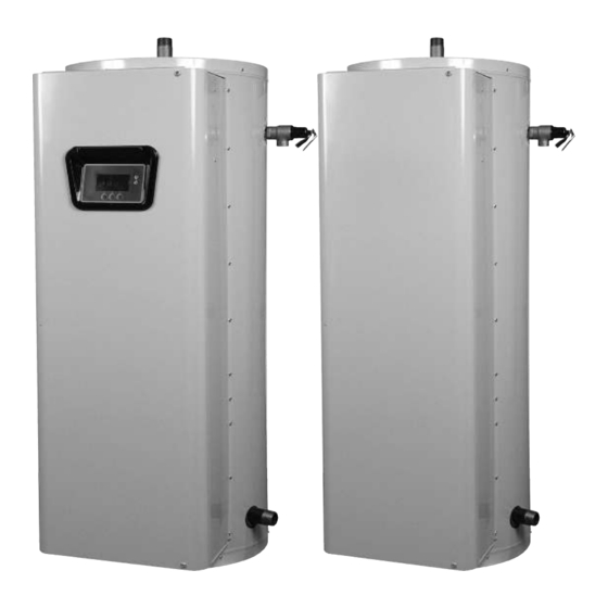
Page 8: Features And Components
FEATURES AND COMPONENTS Figure 2. Electronic Control Modules... - Page 9 FEATURES AND COMPONENTS Figure 3. Surface Mount Control Models...
-
Page 10: Locating The New Water Heater
LOCATING THE NEW WATER HEATER FACTS TO CONSIDER ABOUT THE LOCATION • Near a floor drain. The heater should be located in an area Carefully choose a location for the new water heater. The where leakage of the tank or connections will not result in placement is a very important consideration for the safety of damage to the area adjacent to the heater or to lower floors the occupants in the building and for the most economical use... -
Page 11: Installation
Features and Components illustrations on pages 7 and 8. unnecessary. Should you choose to apply an insulation blanket to this heater, Water temperature over 125°F (52°C) you should follow these instructions below. Failure to follow can cause severe burns instantly these instructions can result in fire, serious personal injury, resulting in severe injury or death. -
Page 12: Water Line Connections
The temperature-pressure relief valve Water temperature over 125°F (52°C) must be installed directly into the fitting of the water heater can cause severe burns instantly designed for the relief valve. Install discharge piping so that resulting in severe injury or death. -
Page 13: Electrical
ELECTRICAL GENERAL An electrical ground is required to reduce risk of electrical The installation must conform with these instructions and the shock or possible electrocution. The water heater should be local code authority having jurisdiction and the requirements connected to a separate grounded branch circuit with over- of the power company. -
Page 14: Amperage Table/Overcurrent Protection
Table 6. Full Load Current for Various Configurations Full Load Current In Amperes Number Of Element Number Of Ther- Number Of Single Phase Three Phase Input Elements wattage mostats Fuses 208V 240V 277V 480V 208V 240V 480V 4000 13.5 4500 5000 6000 - - -... - Page 15 - ELECTRONIC CONTROL MODELS Table 3. Transformer Configuration Note: This table is to be used for 8-tap and 5-tap transformers. Figure 4. Secondary Transformer Coil Table 5. Secondary Transformer Coil Configuration Volts Line On Load On COMMON & 208 COMMON & 240 SECONDARY 120V COMMON &...
-
Page 16: Wiring Diagrams
WIRING DIAGRAMS Figure 5. CCB Control Circuit Diagram - Electronic Control Models... - Page 17 WIRING DIAGRAMS The water heater’s electrical components are pictured and identified on page 7. The following describes the heater circuits and includes wiring diagrams. All heater circuits are designed for 60/50 hertz alternating current. The water heater circuit wiring is 12 AWG, AWM, or TEW type, rated 600 volts, 105°C.
-
Page 18: Conversion To Single Phase
WIRING DIAGRAMS Figure 7. Nine Element - Single and Three Phase CONVERSION TO SINGLE PHASE CONVERSION TO THREE PHASE When the heater is shipped for connection to a three-phase electrical service, it may be connected to a single-phase When heater is shipped for connection to a single-phase electrical service of the same voltage by: electrical service, it may be connected to a three-phase electrical service of the same voltage by:... - Page 19 WIRING DIAGRAMS The water heater’s electrical components are pictured and identified on page 8. The following describes the heater circuits and includes wiring diagrams. All heater circuits are designed for 60/50 hertz alternating current. The water heater circuit wiring is 12 AWG, AWM, or TEW type, rated 600 volts, 105°C. Fusing consists of two 30 amp fuses for each element. Fusing is an optional feature for Canadian models.
-
Page 20: Conversion To Single Phase
WIRING DIAGRAMS Figure 9. Nine Elements - Single And Three Phase CONVERSION TO SINGLE PHASE CONVERSION TO THREE PHASE When the heater is shipped for connection to a three-phase When heater is shipped for connection to a single-phase electrical service, it may be connected to a single-phase electrical service, it may be connected to a three-phase electrical service of the same voltage by: electrical service of the same voltage by:... -
Page 21: Operation
OPERATION GENERAL only). 4. Turn on the electrical disconnect switch. Refer to the Features and Components section of this manual (pages 7 & 8) for the location of components mentioned in 5. Observe the operation of the electrical components during the instructions that follow. -
Page 22: Temperature Regulation
TEMPERATURE REGULATION disabled persons increases the hazards to them. Never allow HIGH TEMPERATURE LIMIT CONTROLS (ECO) small children to use a hot water tap or draw their own bath Both the ELECTRONIC CONTROL and SURFACE MOUNT water. Never leave a child or disabled person unattended in CONTROL model water heaters are equipped with one or a bathtub or shower. -
Page 23: Thermostat Settings - Electronic Controls
UIM (User Interface Module - see Figure 12. UIM (User Interface Module)) located on the front panel of the water heater. Water temperature over 125°F (52°C) can cause severe burns instantly resulting in severe injury or death. Children, the elderly and the physically or mentally disabled are at highest risk for scald injury. -
Page 24: Electronic Control Models Operation
ELECTRONIC CONTROL MODELS OPERATION CONTROL SYSTEM FEATURES MODEL INFORMATION Model information and menu titles are shown in the black bar Advanced Diagnostics: Plain English text and animated icons at the top of the Desktop Screen. display detailed operational and diagnostic information. LCD screen on the front of the water heater displays the Sequence TANK TEMPERATURE of Operation in real time. - Page 25 Table 8. Status Icons ICON DESCRIPTION Water temperature in the tank has fallen. Shaded area of the animated thermometer icon will rise and fall in response to water temperature in the storage tank as sensed from the immersion Temperature Probe. Water temperature in the tank has reached the Operating Set Point.
-
Page 26: Temperatures Menu
Table 9. Water Heater States STATE DESCRIPTION The control system has detected/declared a Fault Condition. The control system will discontinue heating operation and “lock out.” Power to the water heater must be cycled off and on to reset the control Fault system. -
Page 27: Temperature Settings
one additional Differential Setting visible/adjustable for each TANK PROBE OFFSET additional Bank of (3) heating elements. User adjustable setting -5°F to +5°F range; factory default is 0°F. If the current Tank Temperature is sensed (from the immersion Temperature Probe) at 120°F and the offset is OPERATING SEQUENCE adjusted to -5°F the control system would calibrate or “offset”... -
Page 28: Heater Status Menu
HEATER STATUS MENU Desktop Screen during Economy Mode time periods. This menu displays non adjustable operational information. Current Time This menu contains more information that can be displayed on Seven Day 24 hr clock. Use this menu item to set the current one screen of the LCD display. - Page 29 Figure 19. Economy Mode Setup Menu Figure 20. Setpoint Adjustment Adjustable user setting (2°F to 50°F - factory default is 20°F) the control system uses to calculate the “Economy Set Point.” The Economy Set Point = normal Operating Set Point minus the programmed Setpoint Adjustment value.
-
Page 30: Economy Mode Settings
ECONOMY MODE SETTINGS SETPOINT ADJUSTMENT VALUE ACTION DISPLAY From the Desktop Screen, press the Operational Button underneath “MENU” to enter the Main Menu. Notice how the text above the Operational Buttons on the display changes as you navigate through the various menus and screens. Use the Up/Down buttons to select (highlight in black) the Economy Mode Setup menu from the Main Menu. -
Page 31: Economy Mode Settings
ECONOMY MODE SETTINGS TIME CLOCK SETTINGS ACTION DISPLAY From the Desktop Screen navigate to the Economy Mode Setup menu. Use the Up/Down buttons to select (highlight in black) Current Time sub menu. Press the Operational Button underneath “CHANGE” to enter the Current Time sub menu. Use the Up/Down buttons to select the “Weekday”... - Page 32 ECONOMY MODE SETTINGS DAILY OPERATING MODE SETTINGS ACTION DISPLAY Economy Mode All Day: From the Economy Mode Setup menu use the Up/Down buttons to select (highlight in black) the Daily sub menu for “Sun.” Press the Operational Button underneath “CHANGE” to enter this menu.
-
Page 33: Alarm Output Setup Menu
ALARM OUTPUT SETUP MENU menu is done using the same methods for changing the Operating Set Point. Permits user to set the condition (from a list of options) for Service Note: Adjustable user settings in the Alarm Output when the CCB (Central Control Board) ’s integral alarm output Setup menu are unaffected by Restore Factory Defaults. -
Page 34: Current Fault / Alert Menu
FAULT HISTORY MENU Fault History Menu Figure 22. Bottom Of Menu Elapsed Time Total accumulated time the control system (water heater) has This menu displays non adjustable operational information. been energized. The control system records and stores the last 9 Fault and Alert messages in chronological order in this menu. -
Page 35: Restore Factory Defaults Menu
RESTORE FACTORY DEFAULTS MENU This control system menu allows the user to restore most of the control system’s user settings to their factory default settings. User settings in the Alarm Output Setup and Display Settings menus are unaffected by executing Restore Factory Defaults ACTION DISPLAY From the Main Menu use the Up/Down buttons to select (highlight... -
Page 36: Flushing The Water Heater
The anode rod should be inspected after a maximum of three For convenience, sediment removal and element lime scale years and annually thereafter until the condition of the anode removal should be performed at the same time as follows. rod dictates its replacement. LIME SCALE REMOVAL NOTE: Artificially softened water requires the anode rod to be inspected annually. -
Page 37: Troubleshooting Checklist
OTHER SCALE REMOVAL: 4. Put new gaskets on each element and install into tank openings. 1. Flush cleaned ends of elements with water when deliming or cleaning is completed. 5. Attach element wires to connection points from which they were removed. 2. - Page 38 Where possible, remove or lift top cover to examine threads of fittings installed into tank for evidence of leakage. Correct fitting leaks as necessary. Relief valve operation and leakage may be due to water expansion during heating cycle or foreign material on seat of valve.
-
Page 39: Piping Diagrams
PIPING DIAGRAMS... - Page 40 PIPING DIAGRAMS...
- Page 41 PIPING DIAGRAMS...
- Page 42 PIPING DIAGRAMS...
- Page 43 PIPING DIAGRAMS...
- Page 44 PIPING DIAGRAMS...
- Page 45 PIPING DIAGRAMS...
- Page 46 PIPING DIAGRAMS...
- Page 47 PIPING DIAGRAMS...
- Page 48 PIPING DIAGRAMS...
- Page 49 PIPING DIAGRAMS...
- Page 50 PIPING DIAGRAMS...
- Page 51 MANIFOLD KITS Table 11. Manifold Kits with Two Heaters Tank Capacity Part (Gallons) Number 100109231 66 1/4 56 3/4 27 1/4 13 1/4 100109231 70 1/2 60 1/4 31 1/4 9 3/4 100109231 73 1/4 64 1/2 35 3/4 5 1/2 Inlet and outlet size - 1 1/2 All dimensions in inches.
- Page 52 Copyright © 2017 All rights reserved. www.hotwater.com...
Need help?
Do you have a question about the 52 and is the answer not in the manual?
Questions and answers