Table of Contents
Advertisement
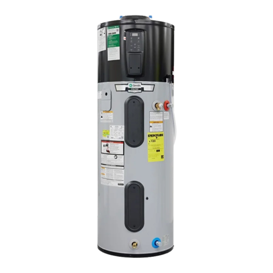
Service Handbook
Heat Pump Water Heater
FOR USE ONLY WITH THESE MODELS:
STANDARD
BRAND
MODEL
A. O. SMITH
HPTS-50
HPTS-66
(WHOLESALE)
HPTS-80
A. O SMITH
HPS10-50H45DV
HPS10-66H45DV
(RETAIL)
HPS10-80H45DV
CANADIAN
HPTS-50 202172T25
HPTS-66 202172T25
A. O. SMITH
HPTS-80 202172T25
(WHOLESALE)
CANADIAN
HPS10C-50H45DV
HPS10C-80H45DV
A. O. SMITH
(RETAIL)
AMERICAN
HPS10250H045DV
HPS10266H045DV
HPS10280H045DV
LOCHINVAR
HPSA050KD
HPSA065KD
HPSA080KD
RELIANCE
10-50-DHPTS
10-66-DHPTS
10-80-DHPTS
STATE
HPSX-50-DHPT
HPSX-66-DHPT
HPSX-80-DHPT
THIS SERVICE HANDBOOK IS FOR USE BY QUALIFIED SERVICE PROFESSIONALS ONLY.
December, 2023
Hybrid Electric
PREMIUM
MODEL
HPTA-40
HPTA-50
HPTA-66
HPTA-80
HPA10-40H45DV
HPA10-50H45DV
HPA10-66H45DV
HPA10-80H45DV
HPTA-50 202172T25
HPTA-66 202172T25
HPTA-80 202172T25
HPTS-50 202172T25
HPTS-66 202172T25
HPTS-80 202172T25
HPA10240H045DV
HPA10250H045DV
HPA10266H045DV
HPA10280H045DV
HPPA040KD
HPPA050KD
HPPA065KD
HPPA080KD
10-40-DHPTA
10-50-DHPTA
10-66-DHPTA
10-80-DHPTA
HPAX-40-DHPT
HPAX-50-DHPT
HPAX-66-DHPT
HPAX-80-DHPT
120V
MODEL
HPTV-50
HPTV-66
HPTV-80
HPV10-50H01DV
HPV10-66H01DV
HPV10-80H01DV
HPV10250H009DV
HPV10266H009DV
HPV10280H009DV
HPV050KD
HPV065KD
HPV080KD
10-50-DHPTV
10-66-DHPTV
10-80-DHPTV
HPVX-50
HPVX-66
HPVX-80
LOW LEAD
CONTENT
2000620230_REV.C
Advertisement
Table of Contents

Related Manuals for A.O. Smith HPTS-50


Summary of Contents for A.O. Smith HPTS-50
- Page 1 A. O SMITH HPS10-50H45DV HPA10-40H45DV HPV10-50H01DV HPS10-66H45DV HPA10-50H45DV HPV10-66H01DV (RETAIL) HPS10-80H45DV HPA10-66H45DV HPV10-80H01DV HPA10-80H45DV CANADIAN HPTS-50 202172T25 HPTA-50 202172T25 HPTS-66 202172T25 HPTA-66 202172T25 A. O. SMITH HPTS-80 202172T25 HPTA-80 202172T25 (WHOLESALE) CANADIAN HPS10C-50H45DV HPTS-50 202172T25 HPS10C-80H45DV HPTS-66 202172T25 A. O. SMITH...
-
Page 2: Table Of Contents
Closed System/Thermal Expansion/T&P Drip ....13 APPENDIX ..............67 Checking and Adjusting the Air Charge of the Thermal Ex- A.O. Smith App Setup and Connectivity ......67 pansion Tank ..............13 Daughter Board Overview (All Models) ......75 Power Cycling the Unit (Standard & Premium Models) ... 14 Control Board Overview (All Models) ....... -
Page 3: Completed Installation (Standard Model)
COMPLETED INSTALLATION (STANDARD MODEL) Water shut-o valve 1/2” (13mm) Conduit Opening Cold water line Hot water line Expansion tank Intake air Exhaust air Intake lter Electrical junction Control panel Condensate drain Condensate line (supplied) Upper element Optional side outlet (capped) and ECO T&P relief valve T&P discharge pipe... -
Page 4: Completed Installation (Premium Model)
COMPLETED INSTALLATION (PREMIUM MODEL) Water shut-o valve 1/2” (13mm) Conduit Opening Cold water line Hot water line Thermal expansion tank Intake air Exhaust air Intake lter Electrical Automatic cold water junction shut-o valve Control panel Condensate drain Condensate line (supplied) Upper element and ECO T&P relief valve... -
Page 5: Completed Installation (120V Model)
COMPLETED INSTALLATION (120V MODEL) Water shut-o valve Cold water line Hot water line Thermal expansion tank Intake air Exhaust air 120V outlet Intake lter Automatic cold water shut-o valve Control panel Condensate drain Power cord Condensate line (supplied) GFCI (ground fault circuit interrupter) Drip loop T&P relief valve... -
Page 6: Important Safety Information
IMPORTANT SAFETY INFORMATION Read and follow all safety messages and instructions in this Important information to keep manual. Fill out this section and keep this manual This is the safety alert symbol. It is used to alert you to in the pocket of the water heater for potential physical injury hazards. -
Page 7: Risks During Installation And Maintenance
IMPORTANT SAFETY INFORMATION RISKS DURING To reduce the risk of property For more information about changing damage, serious injury or death, read the factory thermostat setting(s), OPERATION and follow the precautions below, refer to the “Water Temperature all labels on the water heater, and Adjustment”... -
Page 8: Explosion Risk
IMPORTANT SAFETY INFORMATION Fire and Explosion Risk if Hot Water According to a national standard that the wiring, thermostat(s) or is Not Used for Two Weeks or More. American Society of Sanitary surrounding insulation have been Engineering (ASSE 1070) and most exposed to water in any way (e.g., CAUTION! Hydrogen gas builds up local plumbing codes, the water... -
Page 9: Operation
OPERATION Water Temperature implemented. Additionally, the You may choose to keep the water water temperature setting should be heater in this mode indefinitely. Once Adjustment returned to the manufacturer’s set Electric Mode has been selected, point of 120°F. press the Electric Mode button again The water temperature can be and hold for 5 seconds. -
Page 10: Hybrid Mode
OPERATION Hybrid Mode Sleep Mode scenarios where guests, or additional users, require greater hot water capacity. This is the default, recommended The display will go into “Sleep setting, combining high energy Mode” for energy saving if there is When Guest Mode is selected, the efficiency with reduced recovery no operation on any button for 15 duration timer will be displayed. -
Page 11: Accessing The Maintenance Display
OPERATION Water Temperature Set Point Fahrenheit LED Indicator Control Assembly Lock LED Indicator Days LED Indicator Alert Celsius LED Indicator Indicator Heating Heat Pump Mode Cycle Button Indicator Hot Water+ Mode Button Hybrid Mode Button Guest Mode Button Vacation Mode Button Electric Mode Button... -
Page 12: Troubleshooting
TROUBLESHOOTING WARNING! Do not cap or plug the has been submerged, subjected to pipe will drip. You may be able to T&P Relief Valve or discharge pipe, flooding, or surrounding insulation clear debris from the T&P Relief Valve and do not operate the water heater has been exposed to water in any way. -
Page 13: Closed System/Thermal Expansion/T&P Drip
TROUBLESHOOTING Closed System/ Checking and Adjusting Remove the cap from the air Thermal Expansion/ the Air Charge of the pressure Schrader valve and use the air pressure gauge to T&P Drip Thermal Expansion measure the air pressure charge of Tank the Thermal Expansion Tank. -
Page 14: Power Cycling The Unit (Standard & Premium Models)
TROUBLESHOOTING Power Cycling the Unit Dry-Fire Protection Clearing Error Code (Standard & Premium System Diagnostic To temporarily clear an error code Models) from the control assembly display, This water heater is equipped press the Up and Down Temperature with "Dry-Fire" protection. When Locate and turn OFF the buttons at the same time... -
Page 15: Control Assembly Diagnostic Code Chart
TROUBLESHOOTING CONTROL ASSEMBLY DIAGNOSTIC CODE CHART ERROR CODE INDICATES CORRECTIVE ACTION* No Error Code Displayed High usage, plumbing leak, operating mode 1. Check for plumbing leak. adjustment 2. Adjust temperature; see scald warnings on heater Not Enough Hot Water and in manual. 3. - Page 16 TROUBLESHOOTING ERROR CODE INDICATES CORRECTIVE ACTION* 022 with an alert Icon flashing. Lower element circuit failure 1. Turn off electrical power at the breaker. 2. Check element circuits for resistance of 5-25 NOTICE: Upper element is still operable (also flashing red LED.) ohms (replace if required, see page 18).
- Page 17 TROUBLESHOOTING ERROR CODE INDICATES CORRECTIVE ACTION* 047 with an alert Icon flashing. Smart Valve failure 1. Power off (“Power Cycling the Unit,” page 14). 2. Reconnect power. If error persists, replace Smart NOTICE: Guest Mode and Hot Water + Mode will be (also flashing red LED.) Valve (see “Replacing the Smart Valve,”...
-
Page 18: Maintenance
MAINTENANCE Testing the Element secured to reduce the risk of fire and reduce the risk of scalding. electric shock. Connect a garden hose to the With power to the water Turn the power to the water drain valve and place the heater OFF, remove the heater OFF. -
Page 19: T&P Relief Valve Maintenance
MAINTENANCE T&P Relief Valve NOTICE: Do not turn power back on • Damage caused by corrosive water until the tank is completely full of conditions, mineral deposits, or Maintenance water. other platforms can only be de- termined when a qualified person Read and follow the operating and Refill the tank by opening the removes and inspects the valve and... -
Page 20: Evaporator Coil Maintenance
MAINTENANCE Evaporator Coil Locate and remove the eight Shift the control assembly up Maintenance (8) screws around the bottom and away from the water perimeter of the shroud. heater shroud. The evaporator coils may accumulate Disconnect all six (6) NOTE: Shroud and heat pump dust, dirt and debris if adequate air connectors from the control components removed for clarity. -
Page 21: Check/Reset Energy Cut Off Button (Eco)
MAINTENANCE Check/Reset Energy Replacing ECO Set shroud back into place Cut Off Button (ECO) and secure to heater with the Removing ECO eight (8) perimeter screws previously removed in Step 10. The Energy Cut Off (ECO) shuts off WARNING! Working on an power to the water heater’s elements Fasten the shroud cover to energized circuit can result in severe... - Page 22 MAINTENANCE Installing New ECO Replace the plastic personnel Upper protector and insulation. Access Panel Place the back of the Reinstall the upper access replacement ECO against the panel to the water heater using the tank, just above the mounting two (2) Phillips head screws. clip.
-
Page 23: Replacing Anode
MAINTENANCE Replacing Anode Open a hot water faucet and Remove any ducting from the let the hot water run until it is intake and exhaust duct Removing Anode Rod cool. adaptors. Disconnect cold water supply and hot water supply if WARNING! Working on an WARNING! Be sure the water top connections are used (some units... - Page 24 MAINTENANCE Once the anode rod is Use an adjustable wrench to Restore power to the water exposed, remove the top nut reconnect cold water supply heater. It may take several with a 10 mm hex socket and hot water supply hours for the tank to heat up wrench and remove the wire terminal connections at top of unit if removed.
-
Page 25: Service
SERVICE Replacing Smart Valve Open the drain valve on the Remove the six (6) screws water heater. located around the perimeter Accessing Smart Valve of the shroud cover. Locate and remove the two (2) screws on top WARNING! Working on an of the unit fastening the shroud cover energized circuit can result in severe to the heat pump evaporator. - Page 26 SERVICE Disconnect the 3 pin wire Remove new flex hose from Remove one (1) spring clip harness. Connector will be service kit. Carefully bend flex from kit. Install spring clip located near the cold water hose to allow for easy over Smart Valve outlet and supply opposite from Smart Valve as connection to Smart Valve and hot...
- Page 27 SERVICE Checking for Leaks Returning Heater Back To Normal Operation Install shroud cover to water heater by following the Install intake duct adaptor to instructions outlined in Step shroud cover and secure with 9 in reverse order. three (3) screws. Reconnect any ducting to the intake and exhaust Use an adjustable wrench to adaptors.
-
Page 28: Replacing Control Assembly
Wi-Fi & Bluetooth connectivity, Shift the control assembly up 68-69 in the “A.O. Smith App Setup you will need to contact our Technical and away from the heat and Connectivity” section of this Assistance Hotline to update the pump shroud. - Page 29 SERVICE Replacing The Control Assembly Phillips Head Screw Control Assembly Connector Locations Automatic Cold Water Shut-off Valve Pin Connector (Optional) 2 PIN 18 PIN 8 PIN 9 PIN 5 PIN 24 PIN Figure 32 - Replacing the Control Assembly Residential Hybrid Electric Heat Pump Water Heater Service Handbook • 29...
-
Page 30: Replacing Daughter Board
SERVICE Replacing Daughter Disconnect all six (6) pin Disconnect the four (4) pin Board connectors from the control connectors located on the left assembly board and set it side of the board, the power aside in a safe place. connector located on the right side of Removing Daughter Board the board (red wires), and the spade Locate the daughter board on... - Page 31 SERVICE NOTICE: Some boards may be affixed to bracket using one (1) screw and three (3) snap-in spacers. Remove snap-in spacers from bracket before installing replacement board. Installing New Daughter Board Using the spacers and screws provided in the kit, gently thread screws through the four (4) corner holes in replacement board.
-
Page 32: Replacing Diptube
SERVICE Replacing Diptube of the shroud cover. Locate and Open the drain valve on the remove the two (2) screws on top of water heater. the unit fastening the shroud cover to Removing Diptube the heat pump evaporator. WARNING! Working on an energized circuit can result in severe Evaporator Screw (2x) - Page 33 SERVICE Installing New Diptube perform this step can cause the upper heating element to burn out. Once Apply thread sealant tape to you are certain the tank is completely nipple on replacement full of water, close the hot water diptube. Slide diptube into faucet.
-
Page 34: Replacing Run Capacitor
SERVICE Replacing Run Shift the control assembly up Touch the tip of the Capacitor and away from the heat screwdriver to one of the pump shroud. terminals on the run capacitor and hold it there for Checking Capacitance Disconnect all six (6) pin approximately 20 seconds. - Page 35 SERVICE Installing New Run Capacitor Secure replacement run capacitor to bracket with the two (2) cable ties provided in the kit. Connect wires to the replacement run capacitor as shown in the figure below. To Compressor (Black) To Compressor (White) Figure 45 - Connect Wires to Run Capacitor Reinstall control assembly to heat pump shroud by...
-
Page 36: Replacing Power Cord (120V Units Only)
SERVICE Replacing Power Cord Removing Power Cord Retaining (120V units only) Locate the push wire Cover connector joining the power Accessing the Junction Box cord's white wire (neutral) to 120V Power the water heater's white wire. Cut the Cord Locate the circuit breaker wires at the connector to remove providing power to water them (see Figure 47). - Page 37 SERVICE Returning Heater Back To Strip end of insulation from Install the top cover to the Normal Operation the water heater's black wire junction box using the screws previously cut in Step 6. previously removed in Step 3. Restore power to the water Locate one (1) lever wire connector Tighten the gland to secure heater at the circuit breaker...
-
Page 38: Replacing Condensate Drain Valve
SERVICE Replacing Condensate Locate and remove the eight Disconnect all six (6) pin Drain Valve (8) screws around the bottom connectors from the control perimeter of the shroud. assembly board and set it aside in a safe place. Removing Condensate Drain NOTE: Shroud and heat pump Valve Open a hot water faucet and... - Page 39 SERVICE Use a Phillips screwdriver to Insert the bottom lip of the remove the two (2) screws control assembly into the securing condensate drain opening of the water heater valve to heater. Remove condensate shroud and shift down. Use the guides drain valve and dispose of properly.
-
Page 40: Replacing Condensate Drain Switch
SERVICE Replacing Condensate To avoid damaging gaskets in the flex Evaporator lines, use a pipe wrench at the hot Drain Switch Condensate Drain Pan and cold nipples to counter torque when installing or removing water Accessing Condensate Drain connections. Condensate Switch Switch If equipped, disconnect the automatic... - Page 41 SERVICE approximate cable tie locations to Insert the bottom lip of the Remove the Phillips head re-secure using new cable ties in Step control assembly into the screw from the control 15. Remove condensate switch and opening of the water heater assembly and set it aside in a wires from the heat pump shroud and shift down.
-
Page 42: Replacing Flex Hoses
SERVICE Replacing Flex Hoses Open the drain valve on the Remove the six (6) screws water heater. located around the perimeter Accessing Flex Hoses of the shroud cover. Locate and remove the two (2) screws on top WARNING! Working on an of the unit fastening the shroud cover energized circuit can result in severe to the heat pump evaporator. - Page 43 SERVICE Installing Flex Hoses heater) to shroud cover. Lift intake Use an adjustable wrench to duct adaptor up and away from reconnect cold water supply Inspect gaskets in new flex shroud cover to visually inspect for and hot water supply hoses and confirm they are leaks around the water connections.
-
Page 44: Replacing Expansion Valve Solenoid
SERVICE Replacing Expansion To avoid damaging gaskets in the flex Shift the control assembly up lines, use a pipe wrench at the hot Valve Solenoid and away from the water and cold nipples to counter torque heater shroud. when installing or removing water Accessing Expansion Valve connections. - Page 45 SERVICE Removing Expansion Valve NOTICE: Use caution and do not Insert the bottom lip of the remove additional wires secured by Solenoid control assembly into the wire guides. opening of the water heater Locate expansion valve shroud and shift down. Use the guides Installing New Expansion Valve solenoid within the heat on the control assembly to properly...
-
Page 46: Replacing Fan Motor Assembly
SERVICE Replacing Fan Motor Removing Control Assembly Draining Water Heater Assembly If the backside of the water heater is Remove the Phillips head inaccessible, you will have to drain the screw from the control Disconnecting Power to Water tank to move the heater so access to assembly and set it aside in a Heater the fan motor assembly is available. - Page 47 SERVICE Removing Heat Pump Shroud Removing Fan Motor Assembly Fan Motor Screws (6x) Remove any ducting from the Access fan motor assembly intake and exhaust duct from backside of water adaptors. Use an adjustable heater. wrench to disconnect cold water Locate fan motor power cord supply and hot water supply.
- Page 48 SERVICE Installing New Fan Motor Insert the bottom lip of the Evaporator Assembly control assembly into the Coils opening of the water heater Power Cord Locate new fan motor shroud and shift down. Use the guides assembly provided in kit. on the control assembly to properly Gently hang fan motor seat the controller into place.
-
Page 49: Replacing Upper & Lower Thermistors
SERVICE Replacing Upper & Lower Thermistors Existing Thermistor Wire Harness Removing Upper Thermistor WARNING! Working on an Upper energized circuit can result in severe Thermistor Cut Line injury or death from electrical shock. Turn power OFF. Check wires with a non-contact circuit tester to make sure power is off. - Page 50 SERVICE Splice Existing Thermistor Connector Wire Harness Hex Nut Wire Use Pliers To Squeeze Top Down On Connector, Lower Locking Wires Together Thermistor Replacement Thermistor Figure 92 - Splice Connector Position the thermistor back in the same orientation that it was removed. Use your finger to apply some of the residual thermal grease to both sides of Figure 93 - Removing Lower Access Panel...
- Page 51 SERVICE Installing New Lower Thermistor Locate the thermistor with the red wire lead set aside in Step 7. Using a splice connector included in this kit, insert the ends of the wires into the splice connector as shown in Figure 92.
-
Page 52: Replacing Sensor Wire Assembly
SERVICE Replacing Sensor Wire Open a hot water faucet and Lift the shroud cover up and Assembly let the hot water run until it away from the unit to gain is cool. access to the sensors. NOTICE: It is recommended to replace Removing Sensors WARNING! Be sure the water all four (4) temperature sensors if the... - Page 53 SERVICE Locate Suction Temperature J3 Pin Coil Temperature Sensor (green wires). Cut Connector Sensor (Black Wires) cable tie(s) securing foam insulation around sensor. Slide insulation down to reveal sensor. Pull downward on clip to remove sensor and clip from fixture (see Figure 103). Sensor DO NOT discard insulation.
- Page 54 SERVICE Installing New Sensors Slide insulation up and over Reconnect any ducting to the Suction Temperature Sensor. intake and exhaust adaptors. Run new Coil, Suction and Secure insulation around Discharge Temperature Connect the new wire sensor with two (2) cable ties placed Sensors underneath right side harness to the J3 pin above and below sensor.
- Page 55 SERVICE Figure 107 - Sensor Wire Diagram Residential Hybrid Electric Heat Pump Water Heater Service Handbook • 55...
-
Page 56: Replacing Outlet Thermistor
SERVICE Replacing Outlet of the shroud cover. Locate and Use a flathead screwdriver to remove the two (2) screws on top of Thermistor open the drain valve on the the unit fastening the shroud cover to water heater. the heat pump evaporator. Removing Outlet Flex Hose Evaporator WARNING! Working on an... - Page 57 SERVICE Removing Smart Valve CAUTION! Water may still be Outlet Thermistor present in the valve and flex hose Assembly Location assembly. Place a rag under the flex hose and valve connection points to Disconnect the 8 pin wire prevent water from escaping into the harness located on top of heat pump compartment.
- Page 58 SERVICE Installing Smart Valve NOTICE: Flex hose connections must be aligned with nut retainers to install Assembly Outlet T-Nipple shroud cover to shroud. Adjust flex hoses accordingly. Locate the two (2) large O-Ring O-rings provided in kit. Apply Thermistor Use an adjustable wrench to Wire lubricant and install O-rings Retainer...
- Page 59 SERVICE Returning Heater Back To Normal Operation Install intake duct adaptor to shroud cover and secure with three (3) screws. Reconnect any ducting to the intake and exhaust adaptors. If equipped, reconnect the automatic cold water shut-off valve. The water heater is now ready for normal operation.
-
Page 60: Replacing Inlet & Outlet T-Nipple
SERVICE Replacing Inlet & of the shroud cover. Locate and Use a flathead screwdriver to remove the two (2) screws on top of Outlet T-Nipple open the drain valve on the the unit fastening the shroud cover to water heater. the heat pump evaporator. - Page 61 SERVICE Removing Smart Valve CAUTION! Water may still be Outlet Thermistor present in the valve and flex hose Assembly Location assembly. Place a rag under the flex hose and valve connection points to Disconnect the 8 pin wire prevent water from escaping into the harness located on top of heat pump compartment.
- Page 62 SERVICE Assembling New Outlet Remove masking tape T-Nipple holding thermistor wire to Outlet T-Nipple outlet t-nipple and connect it Locate the two (2) large to the wires leading to the control O-Ring O-rings provided in kit. Apply assembly. Thermistor Wire lubricant and install O-rings Retainer Installing Smart Valve...
- Page 63 SERVICE Returning Heater Back To Use an adjustable wrench to Normal Operation reconnect cold water supply and hot water supply Install intake duct adaptor to connections at top of unit if removed. shroud cover and secure with To avoid damaging gaskets in the flex three (3) screws.
-
Page 64: System Checks
COMPRESSOR CHECK FLOWCHART Allow compressor to cool Compressor Fault Disconnect power to Is compressor and internal thermal switch (Code 083, 084 or 085) water heater shell hot? to reset Clean filter and/or Check run capacitor Are connections Repair loose or damaged evaporator coil if needed terminals for damaged or secure and... - Page 65 COMPRESSOR CHECK FLOWCHART Contact Tech Support. The water heater should be Continue from previous page replaced. Use a multimeter to measure resistance at the ambient, discharge, coil and suction thermistors. Also Extended run over 5 minutes Does compressor run Are thermistors measure the upper and for more than 5 minutes then experiences compressor fault...
-
Page 66: Fan Check Flowchart
FAN CHECK FLOWCHART Fan is not operating. Turn power to water heater back on. Disconnect the Disconnect power to water wires located at the J8 Does impeller heater. Remove exhaust duct terminal on the control rotate adapter. Turn impeller fan. board. -
Page 67: Appendix
A.O. SMITH APP SETUP AND CONNECTIVITY The A. O. Smith App must be downloaded to connect to, control and monitor the water heater remotely. Download App Locate the Quick Reference Guide located on the water heater. Scan the QR code on the Quick Reference Guide with your device to be taken directly to the app (Figure 131). - Page 68 A.O. SMITH APP SETUP AND CONNECTIVITY Once the user account has been registered successfully, the app will prompt you to add the water heater. NOTE: There is no ‘account registration successful’ screen. Instead, if account registration is successful, you will be taken to the Let’s Get Started screen.
- Page 69 A.O. SMITH APP SETUP AND CONNECTIVITY HELP: If you continue to receive the message above, contact the Technical Assistance Hotline which is listed on the water heater’s warranty sheet for further assistance. Once the water heater serial number has been...
- Page 70 A.O. SMITH APP SETUP AND CONNECTIVITY Connect Wi-Fi in App: Enable Wi-Fi connectivity on your device. Confirm the LED indicator is flashing green on the control assembly. If so, select the option to “Connect to Wi-Fi Now” at the bottom of the screen (Figure 145).
- Page 71 A.O. SMITH APP SETUP AND CONNECTIVITY HELP: If your device is unable to connect to the water heater, or if the water heater is unable to connect to your preferred Wi-Fi network (Figures 150 & 151), you may choose to select “Try Again” or select “Set Up Manually” at the bottom of the screen to begin the manual Wi-Fi configuration process.
- Page 72 A.O. SMITH APP SETUP AND CONNECTIVITY The app will prompt you to disconnect from the iCOMM network, and connect to your preferred local Wi-Fi network (Figure 156). Open the Wi-Fi settings menu on your device, search for you preferred Wi-Fi network, and connect.
- Page 73 A.O. SMITH APP SETUP AND CONNECTIVITY Connect Bluetooth in App: Select the option to “Connect via Bluetooth” at the bottom of the screen (Figure 158). Enable Bluetooth on your device. You may do so by selecting the enable button in app (Figure 159), or manually from your device settings.
- Page 74 A.O. SMITH APP SETUP AND CONNECTIVITY Once the water heater has successfully connected to Bluetooth, the app will prompt you with the Water Heater Added screen (Figure 164). Select “Return to Dashboard” at the bottom of the screen to then configure the water heater Set Point, Mode, and Time of Use Rate Plan if applicable.
-
Page 75: Daughter Board Overview (All Models)
DAUGHTER BOARD OVERVIEW (ALL MODELS) J2 LINE 2: • NULL LINE CN2 UNUSED: • PIN 1 - LINE 2 • PIN 2 - UNUSED • PIN 3 - CONNECTED TO K1 RELAY K3 COMPRESSOR RELAY: • CONTROL THE COMPRESSOR POWER CN3 COMPRESSOR POWER: •... -
Page 76: Control Board Overview (All Models)
CONTROL BOARD OVERVIEW (ALL MODELS) Figure 167 - Control Board (Front Side) Figure 168 - Control Board (Back Side) NOTICE: See following page for Control Board callouts. 76 • Residential Hybrid Electric Heat Pump Water Heater Service Handbook... - Page 77 CONTROL BOARD OVERVIEW (ALL MODELS) J1 WATER ALARM: J4 DRIVE COMMUNICATION WITH DAUGHTER BOARD: • PIN 1 - WATER ALARM SENSOR • PIN 1 - COMPRESSOR 12V ENABLE DIG OUT • PIN 2 - DGND • PIN 2 - COMPRESSOR RELAY DIG OUT •...
-
Page 78: Repair Parts (Standard Model)
REPAIR PARTS (STANDARD MODEL) 78 • Residential Hybrid Electric Heat Pump Water Heater Service Handbook... - Page 79 REPAIR PARTS (STANDARD MODEL) REPAIR PARTS ITEM NO. PARTS DESCRIPTION Air Filter Repair parts may be ordered through your plumber, local Fan Motor Assembly distributor, Lowe’s®, or by calling our Technical Assistance Hotline which is listed on your warranty. When ordering parts, Electronic Expansion Valve Solenoid always give the following information: Control Assembly...
-
Page 80: Repair Parts (Premium Model)
REPAIR PARTS (PREMIUM MODEL) 80 • Residential Hybrid Electric Heat Pump Water Heater Service Handbook... - Page 81 REPAIR PARTS (PREMIUM MODEL) REPAIR PARTS ITEM NO. PARTS DESCRIPTION Air Filter Repair parts may be ordered through your plumber, local Fan Motor Assembly distributor, Lowe’s®, or by calling our Technical Assistance Hotline which is listed on your warranty. When ordering parts, Electronic Expansion Valve Solenoid always give the following information: Control Assembly...
-
Page 82: Repair Parts (120V Model)
REPAIR PARTS (120V MODEL) 82 • Residential Hybrid Electric Heat Pump Water Heater Service Handbook... - Page 83 REPAIR PARTS (120V MODEL) REPAIR PARTS ITEM PARTS DESCRIPTION Repair parts may be ordered through your plumber, local Air Filter distributor, Lowe’s®, or by calling our Technical Assistance Fan Motor Assembly Hotline which is listed on your warranty. When ordering parts, always give the following information: Electronic Expansion Valve Solenoid Control Assembly...
-
Page 84: Wire Diagram (Standard & Premium Model)
WIRE DIAGRAM (STANDARD & PREMIUM MODEL) BLUE SHUT OFF VALVE AMBIENT TEMP. SENSOR BLACK COIL TEMP. SENSOR GREEN SUCTION TEMP. SENSOR YELLOW DISCHARGE TEMP. SENSOR CONDENSATE WATER LEVEL SWITCH ANODE CONDENSATE WATER (OPTION OF WATER ALARM SIGNAL a TEMP. SENSOR AND BLACK TANK LOWER TEMP. -
Page 85: Wire Diagram (120V Model)
WIRE DIAGRAM (120V MODEL) BLUE SHUT OFF VALVE AMBIENT TEMP. SENSOR BLACK COIL TEMP. SENSOR GREEN SUCTION TEMP. SENSOR YELLOW DISCHARGE TEMP. SENSOR CONDENSATE WATER LEVEL SWITCH ANODE CONDENSATE WATER (OPTION OF WATER ALARM SIGNAL a TEMP. SENSOR AND BLACK TANK LOWER TEMP. - Page 86 Copyright © 2023, A.O. Smith. All Rights Reserved...
Need help?
Do you have a question about the HPTS-50 and is the answer not in the manual?
Questions and answers