Table of Contents
Advertisement
Quick Links
Advertisement
Table of Contents

Related Manuals for Electrolux IC63316


Summary of Contents for Electrolux IC63316
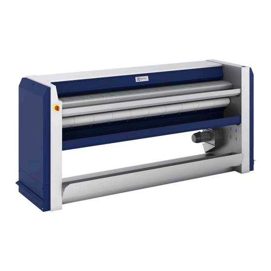
- Page 1 Installation manual Ironers IC63316 — IC63320 Original language 01103054/EN...
-
Page 3: Table Of Contents
Contents Contents 1 Environmental information ........................5 2 Preliminary instructions........................5 3 Data plate explanation .........................6 4 Note about the A.C. power .........................10 5 Safety precautions..........................10 Symbols..........................13 Personal protection equipment....................14 6 Handling ............................15 Unpacking ..........................15 Lifting with a fork-lift truck ......................15 Lifting with handlings straps ......................15 Moving along the ground ......................16 7 Packaging-Weight ..........................16 8 Technical characteristics ........................17... -
Page 5: Environmental Information
Installation manual 1 Environmental information Concerned by providing the end user with useful and necessary environmental information, we wish to precise: • Data about energetic consumptions, wastes (atmospheric and liquid) and sound level are indicated in the para- graph «Technical characteristics». •... -
Page 6: Data Plate Explanation
Installation manual Important Any repairing or maintenance operation should be carried out by a specialist. Important The machine is delivered with a wall instructions paper to be clearly fixed near the machine. Caution Under no circumstances should a gas-heating machine be installed in a building which includes a dry-cleaning machine. - Page 7 Installation manual Electric heating : • P.Max : maximum power installed of your product • Power of the motorization in kW and its isolation class (F) . • Heating power in W .
- Page 8 Installation manual Gas heating : Left side • P.Max : maximum power installed of your product • Power of the motorization in kW and its isolation class (F) . • Heating power in W . • Gas approval number depending on your machine except ETL product (begin by1312/..) Right side •...
- Page 9 Installation manual...
-
Page 10: Note About The A.c. Power
Installation manual 4 Note about the A.C. power According to the EN 60204-1:2018 standard, the machine is provided for A.C. supplies corresponding to the ex- tracted characteristics below : 4.3.2 A.C. supplies Voltage: Steady state voltage: from 0.9 to 1.1 of nominal voltage. Frequency: from 0.99 to 1.01 of nominal frequency continuously. - Page 11 Installation manual CAUTION For the following countries : AT, BE, BG, HR, CY, CZ, DK, EE, FI, FR, DE, GR, HU, IS, IE, IT, LV, LT, LU, MT, NL, NO, PL, PO, PT, RO, SK, SI, ES, SE, CH, TR, UK : This ap- pliance shall not be installed where the public has access.
- Page 12 Installation manual CAUTION The machine can work without the protective casing when the electric supply is not cut off. Interlock the main isolating switch with a padlock. Close the steam or gas inlet valves. THINK OF THE ENVIRONMENT! The use and handling of chemical products such as detergent, chlorine, acids, desca- ling agents, etc may create hazards for health and environment ;...
-
Page 13: Symbols
Installation manual 5.1 Symbols Caution. An exclamation mark inside an equilateral triangle offers the user impor- tant advice about usage, servicing and hazardous conditions. Caution, presence of dangerous current. A flash of lightning with an arrow at its end displayed inside an equilateral triangle, warns the user about the presence of uninsulated "dangerous current"... -
Page 14: Personal Protection Equipment
Installation manual 5.2 Personal protection equipment Given below is a summary table of the Personal Protection Equipment (PPE) to be used during the various phases of the machine’s service life. Phase Protection Safety Gloves Glasses Ear protectors Mask Safety helmet garments footwear Transport... -
Page 15: Handling
Installation manual 6 Handling Important It is obligatory that all these operations are undertaken by handling specialists. 6.1 Unpacking You should have found an instruction handbook and keys to open the machine casings, in the machine. Depending on its destination, the ironer is delivered bare or may be placed on a transport pallet and/or packed with plastic film. -
Page 16: Moving Along The Ground
Installation manual Caution Make sure to place the straps correctly to avoid any bending of parts of the machine. Caution In order to avoid any bending of casings, you should never climb and stand on top of the machine. Moving along the ground The machine frame includes a girder, so that the machine can be moved along the ground using rollers, grinding tracks or a trolley. -
Page 17: Technical Characteristics
Installation manual 1 : Identification plate 2 : Adjustment label (for gas machine only) 8 Technical characteristics Neither base nor sealing are indispensable. It is yet possible to fix the ironer to the floor. To do so, use the holes made to block the machine on the transport pallet. - Page 18 Installation manual...
- Page 19 Installation manual...
- Page 20 Installation manual Machine type Units 3316 3320 Width mm / “ 2030 / 79.92 2445 / 96.26 Length of feeding table = Effective working width mm / “ 1650 / 64.96 2065 / 81.3 Cylinder diameter mm / “ 325 / 12.8 325 / 12.8 Distance between feet mm / “...
-
Page 21: Sound Level
Installation manual Model Heating Appro- Supply voltage Rated intensity Main switch Connection ca- Protection ble section Electric EC & 3 x 32 A 400 V 3 ~ 50/60 Hz 26.7 A 3 x 32 A 4 x 6 mm² / AWG10 Electric 220–240 V 3 ~ 50/60... -
Page 22: Installation
Installation manual Ironing width 3316 3320 Point A Point B Weighted acoustic pressure level (A) in dB(A) Point C Point D Important This ironing machine should only be used for previously washed and pre-dried, machine-ironable textiles. Important In this normal case of use, it is not necessary to connect the exhaust duct to the open air. In the opposite case, the exhaust duct must be connected to the open air, by the shortest way, and with as few bents as possible. - Page 23 Installation manual 2. Install the ironer in an area where it is easily accessible by both operators and service technicians. Make sure that the side of the machine is at least 500 cm (20”) away from walls or other machines. Leave at least 1 m (40") (according to standards applicable) between the machine and a wall or another machine on the left side in order to be able to carry out an intervention on the caisson.
- Page 24 Installation manual...
-
Page 25: Working Place Lighting
Installation manual 11 Working place lighting The lighting should be designed so as to avoid eye strain for the operator ; it should be uniform without any glare, and should be sufficient to detect any hazards. The average lighting value on the working place recommended by the clothing industry for inspecting linen is 500 lux. Whenever possible, the working place should be illuminated by daylight. - Page 26 Installation manual Insert the feeding cable in the designed port (letter B on the foundation plan on the rear left side of the caisson) Dismantle the general switch (E) by activating the red lever (M) upward to separate the body from the head of the switch, and then pull it backward following arrow (F).
- Page 27 Installation manual 400 Volts supply Measure the power supply voltage at the transformer primary with a voltmeter between the transformer 0 and 400 volt terminals. If the voltage is equal to 400 volts, do not touch the transformer connection which must be as shown in the adjacent figure.
- Page 28 Installation manual 230 Volts supply Measure the power supply voltage at the transformer primary with a voltmeter between the transformer 0 and 230 volt terminals. If the voltage is equal to 230 volts, do not touch the transformer connection which must be as shown in the adjacent figure.
- Page 29 Installation manual 120 Volts supply If the voltage is equal to 120 volts, do not touch the transformer connection which must be as shown in the adjacent figure. 208 Volts supply If the voltage is equal to 208 volts, do not touch the transformer connection which must be as shown in the adjacent figure.
-
Page 30: Electric Power Supply
Installation manual Important Once connected, make sure to check the correct order of phase connections. 12.1 Electric power supply : The feeder cable sections mentioned in our literature are given only as a guide . To obtain a value perfectly suited to your own application and which takes account of the different correction factors in respect of your plant, refer to the tables below. -
Page 31: 4Table 4 B2, C And E Correction Factors For Cable Grouping
Installation manual 12.1.4 TABLE 4 B2, C and E correction factors for cable grouping : Number of cables Seated in Cable Duct Wall fixing or Cable Trough Cable Tray 1.00 1.00 1.00 0.80 0.85 0.87 0.65 0.75 0.78 0.57 0.72 0.75 0.50 0.70... -
Page 32: Gas Connection
Installation manual 13 Gas connection : Caution The installation, connection and gas arrival adjustments for the machine must be done by qualified personnel only. 13.1 Gas supply DN 20 (3/4” BSP) : The customer must install a filter and a manual stop valve on the supply side of the machine if natural gas is used. For butane or propane, the customer must install a filter, a manual closing valve and a pressure reducer. -
Page 33: Determinate The Gas Type
Installation manual If the gas inlet pressure (P1) is identical to the nominal pressure of the machine (P2), it is possible to insert a reser- voir as close as possible to the machine in order to protect against any falls in pressure when the machine starts up. Anfd increase the diameter of gas pipe supply to allow the flow rate. -
Page 34: Gas Setting Characteristics Ix 33Xx
Installation manual 14 Gas setting characteristics Ix 33xx : Caution The installation, connection and gas arrival adjustments for the machine must be done by qualified personnel only. 14.1 Legend of symbols used : • I : Machine working with only one gas family •... -
Page 35: Testing Pressure
Installation manual Country Category Pres- sure (mb- II2H3B/P DE — LU II2E3B/P G20/ 20/25 I2E(R)B;I3+ BG — DK — EE — FI – HR — HU — SE — RO II2H3B/P —TR G20/ 20/25 II2Esi3P 37/50 CH — CY — CZ — ES — GB — GR — IE — IT II2H3+ —... -
Page 36: Changing To A Gas In A Different Family (From Type H Or L To Butane Or Propane)
Installation manual 14.3.2 Changing to a gas in a different family (from type H or L to butane or propane) Change the 3 injectors with joints (see correspondence in the tables) Unscrew the fixing screws (V) and remove the adjusting head (J) as weel as its cork (T), keep these parts in case a change would be necessary. - Page 37 Installation manual • A : Inlet • B : Outlet • D : Outlet pressure regulator Adjustment screw plug • E : Inlet pressure tapping • F : Outlet pressure tapping • T : Head regulation...
- Page 38 Installation manual 1 : Close the gas inlet and remove the binding screw from the pres- sure tapping (F) and connect the manometer tube. 2 : The electricity supply must be energized otherwise gas will not be supplied to the burner. 3 : Open and check the gas inlet main burner using the manometer on the pressure tapping (F) 4 : Remove pressure regulator cap (D)
-
Page 39: Tables Of Correspondences
Installation manual 14.5 Tables of Correspondences : TABLE OF CORRESPONDENCES : IRONER 3316 Working Heat emission Pressure at supply Consumption Diameter of Consumption Category Type injectors pressure in injectors in kW (Btu/h) Index of Gas in mm H2O / inch mbar (inch in kg/h in mm... -
Page 40: Fresh Air Inlet
Installation manual Caution Check that no damage has been caused during transport. 15.1 Fresh air inlet To allow the dryer ironer to work at its best, it is important that the laundry air inlet passes through an opening from the outside. The fresh air arrival must be equivalent to the volume of evacuated air (please refer to the output of the fans at zero pressure in the technical characteristics) Important... -
Page 41: Specifications
Installation manual Danger To prevent any risk of burnings, the vapours’evacuation duct of the flatwork ironers of the linen has to be insu- lated (to be done by the customer) Warning It is essential that the diameter of the evacuation pipe should be selected as a function of each installation so that the pressure loss never exceed 200 Pa (0.029 Psi) (Value measured at ambient temperature with a manometer connected to the vertical air outlet (dia 6 or 8 mm) (dia 0.23 or 0.31 “... - Page 42 Installation manual...
-
Page 43: Evacuation System If Several Dryers Are Connected To A Common Evacuation Duct (Except Gas Heating Machines)
Installation manual 15.5 Evacuation system if several dryers are connected to a common evacuation duct (except gas heating machines): If several ironers are installed with a common evacuation duct, the cross section of the evacuation duct must in- crease as a function of the number of installed machines so that each of them operates at the same value of air resistance.. -
Page 44: Check Before Use
Installation manual 16 Check before use The operating inspection must be done by an approved technician. Warning Always make sure that the fan is rotating in the right direction. The fan must rotate in the direction shown on the arrow glued inside the right compartment (see illustration). - Page 45 Installation manual Check the direction of rotation of the fan and the arrow indicating the direction of rotation on the fan. If it is rotating in the wrong direction, invert two of the three phases on the power supply isolating switch to reverse the direction of rotation of the fan.
- Page 46 Installation manual Check again the direction of the rotation of the fan then replace the hose and its collar. Important Before leaving, put the appliance into operation and allow to run a complete cycle. Watch to ensure that all burner system components function correctly.
-
Page 47: Conversion Of Measurement Units
Installation manual 17 Conversion of measurement units This following is a list of correspondences of the main frequency used units, to avoid the need to use measurement unit conversion table. 1 bar = 100 000 Pa British thermal unit 1 Btu = 1 055.06 J 1 bar = 1.019 7 kg/cm²... - Page 50 Electrolux Professional AB 341 80 Ljungby, Sweden www.electroluxprofessional.com...
Need help?
Do you have a question about the IC63316 and is the answer not in the manual?
Questions and answers