Table of Contents
Advertisement
Quick Links
Advertisement
Table of Contents

Related Manuals for KERN Optics OIV 345


Summary of Contents for KERN Optics OIV 345
- Page 1 KERN & Sohn GmbH Ziegelei 1 Tel: +49-[0]7433- 9933-0 D-72336 Balingen Fax: +49-[0]7433-9933-149 E-mail: info@kern-sohn.com Internet: www.kern-sohn.com Operating instructions Video microscope KERN OIV 345 Version 1.1 2024-07 OIV-3-BA-d-2411...
-
Page 2: Table Of Contents
KERN OIV-3 Version 1.1 07/2024 Operating instructions Video microscope Table of contents Technical data ................4 Declaration of conformity ............5 Device overview ................6 Before use ..................7 General information ......................... 7 Basic information (general) ............7 General information on warnings ................... 7 Intended use .......................... - Page 3 10.6 Delete image and video files ....................34 10.7 Open image files ........................34 10.8 Open video files ........................34 10.9 File details ..........................35 Optional accessories ..............36 Troubleshooting ................. 36 Service ..................37 Power supply................37 14.1 Mains connection ........................37 Maintenance, servicing and disposal ........
-
Page 4: Technical Data
1 Technical data CORE OIV 345 Item number/type TOIV 345-B Optical system Greenough System Lighting LED ring light 3.3 W Dimmable lighting Stand Mechanical, upright height 325 mm, base plate 260x320 mm Optical zoom 0.7x - 4.5x Digital zoom 17x - 110x... -
Page 5: Declaration Of Conformity
2 Declaration of conformity The current EC/EU Declaration of Conformity can be found online at: https://www.kern-sohn.com/shop/de/DOWNLOADS/ OIV-3-BA-d-2411... -
Page 6: Device Overview
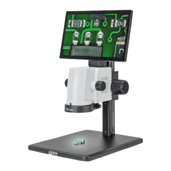
3 Device overview Screen Zoom adjustment wheel Microscope head with camera Focus wheel LED ring light Dimmer LED ring light Microscope stand MicroSD card slot (back side) Operating indicator (LED) USB port (2x) HDMI interface Power connection On/off switch Microscope On/off switch ring light OIV-3-BA-d-2411... -
Page 7: Before Use
4 Before use 4.1 General information The packaging must be opened carefully to prevent the accessories inside from falling to the floor and breaking. In general, a microscope should always be handled with great care, as it is a sensitive precision instrument. -
Page 8: Intended Use
Indicates a prescribed action 5.2 Intended use The OIV 345 is very well suited for inspection and quality control. 5.3 Improper use The OIV 345 must not be used for medical purposes. Do not use the device in potentially explosive atmospheres or for measurements in liquids or on live parts. -
Page 9: Storage And Transportation
Before connecting the device to the mains, you must ensure that you are using the correct input voltage. The information for selecting the correct mains cable can be found on the device, on the back of the product directly above the connection socket. It is essential that you follow this information. -
Page 10: Basic Warnings And Safety Instructions
6 Basic warnings and safety instructions 6.1 Observe the notes in the operating instructions Read the operating instructions carefully before commissioning/using the device, even if you already have experience with KERN devices. Always keep the instructions in the immediate vicinity of the appliance 6.2 Staff training The appliance may only be used by persons who have read and understood the operating instructions, in particular the chapter on safety. - Page 11 ⚠ WARNING Risk of injury due to electric shock! ● Risk of short circuit due to penetration of liquids into the housing! ● Do not immerse the appliance or accessories in water. Make sure that no water or other liquids get into the housing. ●...
-
Page 12: Unpacking And Commissioning
7 Unpacking and commissioning 7.1 Unpacking In the event of a return shipment, please observe the instructions in the chapter "Packaging/return transportation On receipt of the device, please check in advance whether there is any damage caused during transportation and whether the outer packaging, the housing, other parts or even the device itself are damaged. -
Page 13: Assembly
8 Assembly Microscope stand Attach the microscope stand with the base plate and the supplied M5 threaded screws (3x). Tighten the screws on the underside of the plate using the M5 hexagon tool supplied. Set up the microscope stand after successful assembly. -
Page 14: Operation And Function Of The Microscope
8.1 Operation and function of the microscope When the microscope is ready for use after assembly, it must first be connected to the mains via the mains cable. Only insert the mains plug into a suitable socket. Ensure that the mains cable is laid correctly. The following sections describe all the important functions that are useful for operating the device. - Page 15 Connections and interfaces The device has an internal and external software application. Internal software via the screen: To operate the software, a mouse must be connected via the USB port. To do this, plug the USB receiver, which is located in the battery compartment of the wireless mouse supplied, into one of the two USB slots (7).
-
Page 16: Operation And Functionality Of The Software
9 Operation and functionality of the software 9.1 Camera menu Click on the camera to switch to the camera page, set the relevant camera parameters and use the corresponding tools 9.2 Exposure and white balance Automatic exposure is activated. The target value can be set dragging the slider to the left or right. -
Page 17: Adjust Parameters
automatic white balance is activated. Manual adjustment of the red, green and blue levels is not possible The RGB values are regulated automatically by the camera. Automatic white balance is deactivated. The parameters for red, green and blue levels can be adjusted manually. To do this, drag the slider to the left or right accordingly. -
Page 18: Control Elements
9.3 Control elements Magnification: Magnification of the camera. The middle of the magnification is determined by the position of the previous magnification of the scroll wheel; if the scroll wheel has not been magnified, it is set to the middle magnification by default. Note: The magnification is reset to 1.0X after opening the gallery. - Page 19 Vertical mirroring: The entire image is mirrored vertically. The result of this process is that the dot in the top right-hand corner swaps position with the dot in the bottom right-hand corner and the dot in the top left-hand corner swaps position with the dot in the bottom left-hand corner.
-
Page 20: Measurements
9.4 Measurements Click on Measure to switch to the measurement page, take measurements and change measurement attributes. As shown in the illustration on the right. 6.2 Measuring tools Point: Move the mouse pointer to the position to be measured, click the left mouse button and raise it to complete the drawing and display the corresponding coordinates. - Page 21 Polyline: Click the left mouse button to get the different activities, after completion, click the right mouse button to stop, and show the total length of all lines. Note: The length of the dashed line depends on the size of the calibration. Arc: Select three points at different positions and draws an arc according to the distance between the three points and displays the radius and angle of the arc.
- Page 22 circle corresponding to the center of the circle and the end point, and display the radius of the double circle. Note: The radius of the circle depends on the size of the calibration. Double circle: Click three points at different positions with the left mouse button, select a circle corresponding to the three points, select three points at different positions again, click the left mouse button, select a circle in the same way, display the distance between the two circle centers.
-
Page 23: Calibration Setting
Text: Move the mouse to the position to be measured, click on two points with the left mouse button, draw an arrow corresponding to the two points and open the input field. Click OK after the input in the input field is completed, and the entered text will be displayed from the end point of the input text. - Page 24 Add calibration: Click to enter the "Add Calibration" mode, enter the name and length, and then click the "Save" button to save the newly created calibration. Delete calibration: Deletes the currently selected calibration. Note: The first calibration cannot be deleted. Edit calibration: Edit the currently selected calibration.
- Page 25 Click on the drop-down field for the unit to change the unit and click on to save the calibration. Edit calibration completed. Delete calibration sequence: Select the calibration you want to delete in the selection and click on to delete the calibration. OIV-3-BA-d-2411...
-
Page 26: Measurement Attributes
9.6 Measurement attributes Line Color (Line Color): After clicking, a drop-down field appears. After selecting the color, you can change the color. Note: The measured color that was drawn is also changed. Line width (Line Width): After clicking, a drop-down field appears. Select the width and change the line width. -
Page 27: Scale Ruler
9.7 Scale ruler Display of the scale (Scale Disp): If you switch to On, the scale is displayed; if you switch to Off, the scale is closed. Position: Switches the position displayed on the scale. If it is switched to the center, the reference point of the scale is in the center;... -
Page 28: Storage Space
9.10 Storage space If the USB flash drive has several drives, you can select the drive on which the files are to be saved. 9.11 Resetting the data to the factory settings After the factory settings have been restored, the exposure parameters are reset to the default values and automatic exposure is activated. -
Page 29: Set Date / Time
The Group name option is reset to the first group V1-H1 and the display is reset to On. The scale display is reset to Off, the position is reset to the middle, the color is reset to red and the width is reset to 1. 9.12 Set date / time Change the time in Click the mouse to change the year or... -
Page 30: Toolbar
10 Toolbar 10.1 Camera When the system recognizes that the USB flash drive is inserted and the available capacity is sufficient, click to start recording. The top right corner will show that the photo is being saved. During this time, the camera button cannot be clicked again. The camera button can only be clicked when the message "Recording successful"... - Page 31 Minute: Set the minutes. Click the mouse, scroll wheel or click the small button to increase or decrease the control. Second (Second): Set the second speed. Click the mouse, scroll wheel or click the small control button to increase or decrease the speed. Frequency: Specify the number of recordings.
-
Page 32: Video Recording
10.3 Video recording If the system recognizes that the USB flash drive is inserted and the available capacity is sufficient, click on the Video button to start recording. The status of the button The recording time and the indicator are displayed in the top right or left corner. Click the video button again to end the video recording. -
Page 33: Rename Image And Video Files
to the previous page to the next page Displays the current page number. After clicking, a drop-down field appears from which you can select the page you want to jump to. Sort order, date or name. Sort order, ascending or descending. Select an image or video and click Delete to delete the image or video. -
Page 34: Delete Image And Video Files
10.6 Delete image and video files You can select one or more image/video files for deletion. After you have selected the file(s), the file(s) will have a blue background. Then click on delete the file(s). Deleting the menu bar, which is called up by right-clicking on the file, can only delete the currently selected individual file. -
Page 35: File Details
10.9 File details Right-click on the desired file, call up the menu bar and click on "Details" to display the details of the current file. OIV-3-BA-d-2411... -
Page 36: Optional Accessories
11 Optional accessories Accessories Auxiliary lens 0.5x OBB-A3225 Auxiliary target 2.0x OBB-A3226 Solder protection lens OBB-A3227 Cleaning set for microscopes OCS 901 12 Troubleshooting Problem Cause Solution Contaminants are Stains or dust on the picture Clean sample present on the sample Impurities are on the Clean lens lens surface... -
Page 37: Service
13 Service If, despite studying these operating instructions, you still have questions about commissioning or operation, or if, contrary to expectations, a problem should occur, please contact your specialist dealer. The device may only be opened by trained service technicians authorized by KERN. 14 Power supply 14.1 Mains connection The microscope may only be connected to the mains if the information... -
Page 38: Maintenance, Servicing And Disposal
15 Maintenance, servicing and disposal Disconnect the appliance from the power supply before carrying out maintenance, cleaning or repair work. 15.1 Maintenance and cleaning The appliance must always be kept clean and regularly freed from dust. Before wiping the appliance when it gets wet, make sure that the power is switched off. - Page 39 Old appliances and accessories must not be disposed of with household waste. The operator must dispose of the packaging and the device at the place of use in accordance with the applicable national or regional legislation The device consists of various components and materials, such as •...
-
Page 40: Battery Law
16 Battery law Note in accordance with the Battery Act - BattG: INFORMATION • The following information is valid for Germany. In connection with the sale of batteries and rechargeable batteries, we are obliged as a dealer under the Battery Act to inform end users of the following: •... -
Page 41: Further Information
17 Further information The illustrations may differ slightly from the product. The descriptions and illustrations in these operating instructions are subject to change without notice. Further developments to the device may result in such changes. language versions include non-binding translation. The original German document is binding OIV-3-BA-d-2411...
Need help?
Do you have a question about the OIV 345 and is the answer not in the manual?
Questions and answers