Table of Contents
Advertisement
Quick Links
Product No.
ELPM482-00005
CONFIDENTIAL
PRODUCT SPECIFICATION
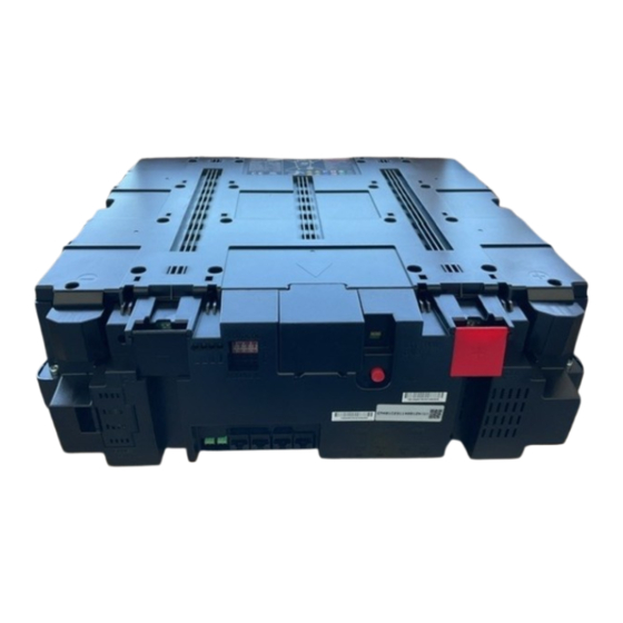
4.84kWh Lithium Ion Energy Storage
System
1. Customer: Vertiv
2. Product Number: ELPM482-00005
3. Received Marking
Division
Signature
Date
4. Date of Application (YYYY/MM/DD):
5. Supplier: SAMSUNG SDI Co., Ltd.
Issued
Revision
/
/
Development
Checked
Approved
0.2
/
/
Checked
/
/
QA
Approved
Advertisement
Table of Contents

Related Manuals for Samsung ELPM482-00005


Summary of Contents for Samsung ELPM482-00005
- Page 1 Revision CONFIDENTIAL PRODUCT SPECIFICATION 4.84kWh Lithium Ion Energy Storage System 1. Customer: Vertiv 2. Product Number: ELPM482-00005 3. Received Marking Division Signature Date 4. Date of Application (YYYY/MM/DD): 5. Supplier: SAMSUNG SDI Co., Ltd. Development Issued Checked Approved Checked Approved...
-
Page 2: Revision History
Product No. ELPM482-00005 Revision CONFIDENTIAL Revision History Revision Date Description Pages Changed 2018.09.06 Draft 2019.01.25 Draft 2019.03.11 Revised Protection function for safety. 26 - 31 7. Protection 8. save data and period 2019.03.19 4.3 BMS block diagram 4.4 BMS Key components 7. -
Page 3: Table Of Contents
Product No. ELPM482-00005 Revision CONFIDENTIAL Table of Contents Revision History ........................... 2 Table of Contents ......................... 3 Tables ............................5 Figures ............................6 Acronyms and Abbreviations ......................7 1. Product Overview ........................8 1.1 Scope ............................8 1.2 Product Description ........................8 2. - Page 4 Product No. ELPM482-00005 Revision CONFIDENTIAL 11.6 Preparation Stage—Recommended Tools/Instruments ............41 11.7 Preparation Stage—Appearance Inspection ................. 42 11.7.1 Appearance Inspection for Module ................42 11.8 Module Installation Stage ..................... 43 (8) Check the LED Status: Refer the section ................. 45 (13) Check the LED Status: Refer the section 8.
-
Page 5: Tables
Product No. ELPM482-00005 Revision CONFIDENTIAL Tables Table 1: Acronyms and Abbreviations ..................7 Table 2 : Component Information ................... 8 Table 3 : Safety Symbols ......................9 Table 4: General Specification ....................13 Table 5 : Connector information ................... 16 Table 6 : Protocol ID Dip Switch Configuration .............. -
Page 6: Figures
Product No. ELPM482-00005 Revision CONFIDENTIAL Figures Figure 1: Module Assembly ..................... 8 Figure 2: Storage Guide ......................12 Figure 3 : Module Drawing ....................14 Figure 4 : Module Front Structure..................14 Figure 5 : Connector Naming ....................16 Figure 6 : External LED Circuit ....................17 Figure 7 : Dry Contact Circuit .................... -
Page 7: Acronyms And Abbreviations
Product No. ELPM482-00005 Revision CONFIDENTIAL Acronyms and Abbreviations The following acronyms and abbreviations are used in this manual. Table 1: Acronyms and Abbreviations Abbreviations Full Name Battery Management System Energy Storage System Over Temperature Protection Over Voltage Protection Termination Resistor... -
Page 8: Product Overview
Lithium Ion Energy Storage System (“ESS” hereinafter) manufactured by Samsung SDI Co., Ltd. For Vertiv. It is intended to provide certified personnel and users with information on safe handling, installation and usage of the specified product. -
Page 9: Safety Information And Handling
Product No. ELPM482-00005 Revision CONFIDENTIAL 2. Safety Information and Handling This Part details the safety information that personnel must fully understand and follow while transporting, storing, installing, operating or servicing the ESS. Before proceeding with unloading, unpacking, handling, installation and operation, read the following details. -
Page 10: General Safety Information
Product No. ELPM482-00005 Revision CONFIDENTIAL Do not dispose in trash Transport legally. Follow manufacturer’s instructions for disposal. Please recycle Lithium ion battery. Do not discard. Qualified technicians use this manual for service and replacement. This symbol is attached to the position near the DC+, DC- and communication port. -
Page 11: Electrolyte Vent Product
Product No. ELPM482-00005 Revision CONFIDENTIAL Seek immediate medical attention. 2.2.3 Electrolyte Vent Product The Lithium-Ion chemistry used in ESS contains an organic solvent-based electrolyte. If ESS is misused, damaged or abused, internal cell pressure may increase to excessive levels. Each cell within the ESS is equipped with a non-resettable vent so that if internal cell pressure increases, the cell’s vent will activate releasing the electrolyte vent products. -
Page 12: Storage
Product No. ELPM482-00005 Revision CONFIDENTIAL 2.2.6 Storage Follow the guidelines below when storing the Battery Modules. The battery module box should be upright as in Figure 2 below. Do not stack or place upside down when storing the battery module box. -
Page 13: Module Specification(T.b.d)
Product No. ELPM482-00005 Revision CONFIDENTIAL 3. Module Specification(T.B.D) Table 4: General Specification Item Specification Remarks Dimension[mm] 446 x 440 x 158.2 Weight[kg] About 34.5 Minimum Capacity 1/3C (31A) charge and 94Ah discharge @R.T Cell Configuration 14S1P Nominal Capacity 4.84kWh 1/3C @R.T Nominal Voltage 51.52V DC... -
Page 14: Product Structure And Block Diagram
Product No. ELPM482-00005 Revision CONFIDENTIAL recommend recharge the module. If not, the degradation of cell cycle life can be accelerated. Also if the module voltage was being discharged deeper than 21V, it will be irrevocably damaged, resulting in a permanent failure. In case the... -
Page 15: Bms Block Diagram
Product No. ELPM482-00005 Revision CONFIDENTIAL 4.3 BMS block diagram 4.4 BMS Key components Item Key components Spec STM32F105VCT6 Current Sensing IC R2A24060 ML5236 14Ch Shunt Resistor PSR500HTQFH1L00 1mΩ, 1%, 5W, 2 Parallel 2nd protection fuse BZ05-640 75A, 64Ω FDB019N807L Rated 270A, 80Vdc 5 Parallel... -
Page 16: Connector Configuration
Product No. ELPM482-00005 Revision CONFIDENTIAL 5. Connector Configuration Figure 5 : Connector Naming Table 5 : Connector information Start point NAME Housing Pin No Pin Map CAN2_H CAN2_L GND_CAN External Communication RS485 + (CAN, RS485) RS485 - RS485 - RS485 +... -
Page 17: Dry Contact, External Led Specification
Product No. ELPM482-00005 Revision CONFIDENTIAL Contact 2 Contact1 Dry Contact Contact 2 BATT CN13 ON/OFF SWITCH 5.1 Dry Contact, External LED Specification 1) External LED - 1 channels, Coil driving specification: 5VDC/10mA max - Normal operating: LED ON, Alarm/Protection: LED Toggle... -
Page 18: Figure 8 : On/Off Switch Circuit
Product No. ELPM482-00005 Revision CONFIDENTIAL . Contact specification: 60VDC↑, 100mA ↑ . Withstanding voltage: 1,000 VAC ↑ - Operating Sequence . Power ON: Push “ON/OFF SWITCH” on module of CAN ID ‘1’ for more than 2 seconds. . Power OFF: Push “ON/OFF SWITCH” on CAN ID ‘1’ for more than 5 seconds Caution: Do not press the power switch button for more than 5 seconds during power on status. -
Page 19: Protocol
Product No. ELPM482-00005 Revision CONFIDENTIAL 6. Protocol 6.1 Protocol ID Set Dip switch configuration Protocol ID Dip-switch’s configuration is as follow. Table 6 : Protocol ID Dip Switch Configuration ID Dip-Switch Switch No Functions Protocol ID Bit 1 Protocol ID Bit 2... -
Page 20: Module To Pcs Can Communication
Product No. ELPM482-00005 Revision CONFIDENTIAL Standard Even Extended 38400 Standard None Extended Even Standard 57600 Extended None Standard Even Extended 115200 Standard None 6.2 Module to PCS CAN Communication - Baud rate: 500kbps - Format: CAN2.0A 11 bit identifier - Data Length: 8byte - CAN data is transmitted with encoding in little endian –... - Page 21 Product No. ELPM482-00005 Revision CONFIDENTIAL Over-Voltage Protection Under-Voltage Protection Over-Temperature Protection Charge Over-Current Protection Discharge Over-Current Protection FET Over-Temperature Protection 0x501 System Protection Status Tray-ID Error Protection PCS Comm. Error Protection FET Failure FET Over-Temperature Failure Under-Voltage Shutdown Cell Voltage Imbalance Protection...
- Page 22 Product No. ELPM482-00005 Revision CONFIDENTIAL Tray-ID Cell Voltage #10 0.001 0x5F3 Cell Voltage #11 0.001 Cell Voltage #12 0.001 Tray-ID Cell Voltage #13 0.001 Cell Voltage #14 0.001 0x5F4 Reserved Reserved Reserved...
-
Page 23: Module To Pcs Rs485 Communication
Product No. ELPM482-00005 Revision CONFIDENTIAL 6.3 Module to PCS RS485 Communication - Baud rate: 9600bps, 19200bps, 38400bps, 57600bps, 115200bps - Start-Bit: 1 - Data-Bit: 8 - Stop-Bit: 1 - Parity-Bit: Even / Odd / None Table 9 : Detailed RS485 Communication... - Page 24 Product No. ELPM482-00005 Revision CONFIDENTIAL System Protection Status Bit 0: Over-Voltage Bit 1: Under-Voltage Bit 2: Over-Temperature Bit 3: Reserved Bit 4: Charge Over-Current Bit 5: Discharge Over-Current Bit 6: FET Over-Temperature Bit 7: Reserved 0x04 0007 System Protection Status Bit 8: Tray-ID Error Bit 9: PCS Comm.
- Page 25 Product No. ELPM482-00005 Revision CONFIDENTIAL Minimum Cell Voltage 0x04 0017 Minimum Cell Voltage Minimum cell voltage in all tray Minimum Cell Voltage Position 0x04 0018 Minimum Cell Voltage Position Tray-ID Average Cell Temperature ℃ 0x04 0019 Average Cell Temperature Average cell temperature in all tray Maximum Cell Temperature ℃...
- Page 26 Product No. ELPM482-00005 Revision CONFIDENTIAL Tray Alarm Status Bit 0: Over-Voltage Bit 1: Under-Voltage Bit 2: Over-Temperature Bit 3: Under-Temperature Bit 4: Charge Over-Current Bit 5: Discharge Over-Current Bit 6: FET Over-Temperature Bit 7: Tray Voltage Imbalance 0x04 006A Tray Alarm Status...
- Page 27 Product No. ELPM482-00005 Revision CONFIDENTIAL ℃ 0x04 0074 FET Temperature FET temperature in tray ℃ 0x04 0075 Precharge Resistor Temperature Precharge Resistor temperature in tray Bit 0: Pre-charge FET Tray Switch Status Bit 1: Charge FET Bit 2: Discharge FET...
-
Page 28: Protection
Product No. ELPM482-00005 Revision CONFIDENTIAL 7. Protection BMS Protection will be activated in detection condition, and be deactivated in release condition. Table 10 : Protection Specification Protection Set Release Set Item Level Description Prechg Condition Condition Fuse (Renesas) Tray Voltage ≥ 60.2V Set MCCV/MDCV "0A"... - Page 29 Product No. ELPM482-00005 Revision CONFIDENTIAL Protection Set Release Set Item Level Prechg Description Condition Condition Fuse Set MCCV/MDCV "0A" Set Alarm Flag Tray Precharge Resistor Temp≥80℃ | Median Tray Voltage - My Tray | Median Tray Voltage - My Voltage...
- Page 30 Product No. ELPM482-00005 Revision CONFIDENTIAL Protection Set Release Set Item Level Description Prechg Condition Condition Fuse Set MCCV/MDCV "0A" |Current| ≥ 150A Fusing Protection Set Permanant Flag Over Protection 150 > |Current| ≥ 63A Curren Set MCCV/MDCV "0A" Curren Power Reset Protection 63A >...
-
Page 31: Table 11 : Protection Control
Product No. ELPM482-00005 Revision CONFIDENTIAL Table 11 : Protection Control Rack BMS will send alarm and protection/Dry contact signal when there is a fault detected in the Battery System. The charger unit, the inverter unit or the PCS must control the battery unit accordingly if alarm and protection/Dry contact are detected by the Rack BMS. -
Page 32: Save Data And Period
Product No. ELPM482-00005 Revision CONFIDENTIAL 8. save data and period PCS will be saved RS-485 data and daily log for guarantee life and safety of battery. Table 12 : Save data and period data list period Function code Address(Hex) 0x04... -
Page 33: Led Indication
Product No. ELPM482-00005 Revision CONFIDENTIAL 8. LED Indication 8.1 Normal Status Display At the normal operation state, the battery LED shows SOC level. Table 13 : SOC Indicator 8.2 Error Status Display If BMS detects alarm or protection conditions, the LEDs blink . -
Page 34: Module Id Dip Switch Configuration
Product No. ELPM482-00005 Revision CONFIDENTIAL 9. Module ID Dip Switch Configuration ID Dip-switch’s configuration is as follow. Module ID can be set with switch number from 1 to 6. Switch number 7 is only used in single Module mode. Switch number 7 is used to power on BMS. -
Page 35: Module Id Set
Product No. ELPM482-00005 Revision CONFIDENTIAL 9.1 Module ID set Module ID should be set before installation. ID can be set using dip-switch in front of Module. ID is composited of binary number from 0(0000001) to 19(1100101). Default set value is 0(0000001). -
Page 36: Dip Switch Set Of Single Module System
Product No. ELPM482-00005 Revision CONFIDENTIAL 9.2 Dip Switch Set of Single Module System In case of Single Module system, ID is set as below. Module ID is number 0(0000001) and switch number 7 is turned on. Table14. Single ID Switch set... -
Page 37: Drawings
Product No. ELPM482-00005 Revision CONFIDENTIAL 10. Drawings Figure 11 : Module Drawings... -
Page 38: Installation
Product No. ELPM482-00005 Revision CONFIDENTIAL 11. Installation 11.1 Overview This section provides detailed information on assembly and installation of ESS. Please be sure to read and fully understand installation manual documents before proceeding Installation. Fully installed ESS is shown as below in Figure 12. -
Page 39: Installation Procedure
Product No. ELPM482-00005 Revision CONFIDENTIAL Single Module configuration is shown below in Figure 13. Figure 13 : Single Module configuration 11.2 Installation Procedure This product must be installed by following the procedure below: 2. Module 3. Communication 1. Preparation Stage... -
Page 40: Preparation Stage-Procedure
Product No. ELPM482-00005 Revision CONFIDENTIAL 11.3 Preparation Stage—Procedure For the preparation stage, perform the following steps: 1. Create the installation plan and check the equipment units and instruments for installation. 2. Check the arrival schedule of the parts required. 3. Perform unpacking. -
Page 41: Preparation Stage-Communication And Power Wire
Revision CONFIDENTIAL 11.5 Preparation Stage—Communication and Power wire. Communication and power wires are not provided by Samsung SDI, but must be provided by customer to use to racks. Customer-supplied Communication and power wires must adhere to the specifications below. 11.5.1 Communication Wires Signal connectors use RJ-45 Type connector and Ethernet cable (above CAT-5 standard). -
Page 42: Preparation Stage-Appearance Inspection
CONFIDENTIAL 11.7 Preparation Stage—Appearance Inspection During appearance inspection, the inspector should check the following cases: CAUTION If there are any defects during the visual inspection, contact the SAMSUNG SDI customer service department. 11.7.1 Appearance Inspection for Module After transporting the module to the designated place, check the followings: ... -
Page 43: Module Installation Stage
Product No. ELPM482-00005 Revision CONFIDENTIAL Check the LED Status: Refer the section 5) Check the Module Voltage and Internal impedance. 6) Push “ON/OFF SWITCH” on any Module for more than 5 seconds 7) Check the LED OFF Table 18 : Module Voltage and Internal Impedance... -
Page 44: Figure 22 : Location Of Tr Switch
Product No. ELPM482-00005 Revision CONFIDENTIAL Figure 22 : Location of TR switch In case of single Module system, the TR switch must be switched on. (6) Connection the Signal Wire 1) Signal connector (Not provided) Signal connectors use RJ-45 Type connector and Ethernet cable (above CAT-5 standard). -
Page 45: Check The Led Status: Refer The Section
Product No. ELPM482-00005 Revision CONFIDENTIAL Push “ON/OFF SWITCH” on module of CAN ID ‘1’ for more than 2 seconds. All Modules will be turned on automatically. Caution: Do not press the power switch button for more than 5 seconds during power on status. -
Page 46: Figure 26 : Turn Off System
Product No. ELPM482-00005 Revision CONFIDENTIAL (10) Power Off the modules - System Turn Off Sequence Push “ON/OFF SWITCH” on CAN ID ‘1’ for more than 5 seconds. Then all Module power is off except switch-pushed Module. And switch-pushed Module LEDs blink. -
Page 47: Check The Led Status: Refer The Section 8. Led Indication
Product No. ELPM482-00005 Revision CONFIDENTIAL (12) Power on the Modules (13) Check the LED Status: Refer the section "LED indication" Confirm the LED of Normal status 11.9 Communication Check(T.B.D) After installation, wiring, and configuration are completed, you must check the communication status by connecting the CAN cable and run the monitoring program to see whether shows BMS data correctly. -
Page 48: Contact Information
Product No. ELPM482-00005 Revision CONFIDENTIAL Contact Information Corporate Headquarters Samsung SDI, Co. Ltd. 428-5 Gongse-dong, Giheung-gu, Yongin-si, Gyeongki-do Republic of Korea Telephone: 82-31-8006-3369 Homepage: www.samsungsdi.com Technical Support (Korea) Samsung SDI, Co. Ltd. ESS Sales Group 428-5 Gongse-dong, Giheung-gu, Yongin-si, Gyeongki-do...
Need help?
Do you have a question about the ELPM482-00005 and is the answer not in the manual?
Questions and answers