Table of Contents
Advertisement
Quick Links
Advertisement
Table of Contents

Related Manuals for Asus AAEON SRG-IMX8PL


Summary of Contents for Asus AAEON SRG-IMX8PL
- Page 1 SRG-IMX8PL IoT Gateway System User’s Manual 1 Last Updated: June 17, 2024...
-
Page 2: Copyright Notice
Copyright Notice This document is copyrighted, 2024. All rights are reserved. The original manufacturer reserves the right to make improvements to the products described in this manual at any time without notice. No part of this manual may be reproduced, copied, translated, or transmitted in any form or by any means without the prior written permission of the original manufacturer. - Page 3 Acknowledgement All other products’ name or trademarks are properties of their respective owners. Microsoft Windows® is a registered trademark of Microsoft Corp. ⚫ NXP is a trademark NXP B.V. ⚫ Arm® and Cortex® are registered trademarks of Arm Limited (or its ⚫...
- Page 4 Packing List Before setting up your product, please make sure the following items have been shipped: Item Quantity SRG-IMX8PL ⚫ 2pin 3.81mm Power Terminal block w/lock ⚫ 18pin 2.54mm Phoenix plug in Connector/lock ⚫ If any of these items are missing or damaged, please contact your distributor or sales representative immediately.
- Page 5 About this Document This User’s Manual contains all the essential information, such as detailed descriptions and explanations on the product’s hardware and software features (if any), its specifications, dimensions, jumper/connector settings/definitions, and driver installation instructions (if any), to facilitate users in setting up their product. Users may refer to the product page on AAEON.com for the latest version of this document.
- Page 6 Safety Precautions Please read the following safety instructions carefully. It is advised that you keep this manual for future references All cautions and warnings on the device should be noted. Make sure the power source matches the power rating of the device. Position the power cord so that people cannot step on it.
-
Page 7: To Prevent Damage
If any of the following situations arises, please the contact our service personnel: Damaged power cord or plug Liquid intrusion to the device iii. Exposure to moisture Device is not working as expected or in a manner as described in this manual The device is dropped or damaged Any obvious signs of damage displayed on the device... - Page 8 FCC Statement This device complies with Part 15 FCC Rules. Operation is subject to the following two conditions: (1) this device may not cause harmful interference, and (2) this device must accept any interference received including interference that may cause undesired operation.
- Page 9 China RoHS Requirements (CN) 产品中有毒有害物质或元素名称及含量 AAEON System QO4-381 Rev.A0 有毒有害物质或元素 部件名称 铅 汞 镉 六价铬 多溴联苯 多溴二苯 (Pb) (Hg) (Cd) (Cr(VI)) (PBB) 醚(PBDE) 印刷电路板 × ○ ○ ○ ○ ○ 及其电子组件 外部信号 × ○ ○ ○ ○ ○ 连接器及线材 外壳 ○...
- Page 10 China RoHS Requirement (EN) Hazardous and Toxic Materials List AAEON System QO4-381 Rev.A0 Hazardous or Toxic Materials or Elements Component Name PCB and Components Wires & Connectors for Ext.Connections Chassis CPU & RAM HDD Drive LCD Module Optical Drive Touch Control Module Battery This form is prepared in compliance with the provisions of SJ/T 11364.
-
Page 11: Table Of Contents
Table of Contents Chapter 1 - Product Specifications..................1 Specifications........................ 2 Block Diagram ......................4 Chapter 2 – Hardware Information ..................5 Dimensions ........................6 Jumpers and Connectors ..................8 List of Connectors ...................... 10 2.3.1 SPI/I2C/GPIO Connector (CN4) ..............11 2.3.2 Full-size Mini Card Slot (CN12) ............... - Page 12 3.1.2 Log In ........................33 I/O Control Command and Example ..............33 3.2.1 CANBus ......................33 3.2.2 Ethernet ......................34 3.2.3 PCIe (M.2 E-Key) ....................36 3.2.4 RTC ........................37 3.2.5 SD Card ......................37 3.2.6 Serial ........................39 3.2.6.1 RS-232 .......................
-
Page 13: Chapter 1 - Product Specifications
Chapter 1 Chapter 1 - Product Specifications... -
Page 14: Specifications
Specifications System Processor NXP i.MX8M Plus Quad-Core Arm® Cortex®-A53, up to 1.6 GHz (Default: w/ NPU, Optional: w/o NPU) Memory Onboard LPDDR4, up to 4GB (8GB by request) Storage eMMC 5.1 16GB/32GB (Optional: 64GB/128GB) Micro SD Card x 1 Real Time Clock RTC x 1, with 3V CR2032H Lithium Battery Security TPM 2.0 (Optional) - Page 15 Power Connector 2-Pin 3.81mm Pitch Phoenix Connector Debug Port Micro USB x 1 Expansion Slot M.2 2230 E-Key x 1, support Wi-Fi/BT module Full-size Mini Card x 1, support 4G module Other — Power Supply Power Requirement DC 9V ~ 36V (Optional: 12V) Power Consumption 9.36W (Full Loading) MTBF...
-
Page 16: Block Diagram
Block Diagram Chapter 1 – Product Specifications... -
Page 17: Chapter 2 - Hardware Information
Chapter 2 Chapter 2 – Hardware Information... -
Page 18: Dimensions
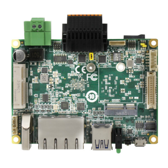
Dimensions System Chapter 2 – Hardware Information... - Page 19 PCBA Chapter 2 – Hardware Information...
-
Page 20: Jumpers And Connectors
Jumpers and Connectors Component Side Chapter 2 – Hardware Information... - Page 21 Solder Side Chapter 2 – Hardware Information...
-
Page 22: List Of Connectors
List of Connectors Please refer to the table below for all of the board’s connectors that you can configure for your application Label Function SPI/I2C/GPIO Connector CN12 Full-size Mini Card Slot CN16 Micro SD Slot CN25 LVDS Port Inverter/Backlight Connector CN26 LVDS Connector CN27... -
Page 23: Spi/I2C/Gpio Connector (Cn4)
2.3.1 SPI/I2C/GPIO Connector (CN4) Pin Name Signal Type Signal Level ECSPI_SS0 +3.3V I2C_SCL +3.3V ECSPI_MOSI +3.3V I2C_SDA +3.3V ECSPI_MISO +3.3V GPIO_3 +3.3V ECSPI_SCLK +3.3V GPIO_4 +3.3V Note: Pitch = 1.27mm. Chapter 2 – Hardware Information... -
Page 24: Full-Size Mini Card Slot (Cn12)
2.3.2 Full-size Mini Card Slot (CN12) Pin Name Signal Type Signal Level +3.3VSB +3.3V Chapter 2 – Hardware Information... - Page 25 Pin Name Signal Type Signal Level W_DISABLE# (Note 1) +3.3V PERST# +3.3V +3.3VSB +3.3V SMB_CLK (Note 1) +3.3V SMB_DATA (Note 1) +3.3V USB_D- DIFF USB_D+ DIFF +3.3VSB +3.3V +3.3VSB +3.3V +3.3VSB +3.3V Chapter 2 – Hardware Information...
-
Page 26: Micro Sd Slot (Cn16)
Note 1: The function is disabled by unmounted 0ohm jumper. W_DISABLE#: R333, SMB_CLK: R328, SMB_DATA: R326 Note 2: The driving current supports up to 2A. Note 3: For 4G full-size mini card. 2.3.3 Micro SD Slot (CN16) Pin Name Signal Type Signal Level SD_DAT2 +3.3V... -
Page 27: Audio Port (Cn27)
2.3.4 Audio Port (CN27) Pin Name Signal Type Signal Level LINE_R_OUT +3.3V MIC_R +3.3V LINE_L_OUT +3.3V MIC_L +3.3V GND_AUDIO GND_AUDIO LINE_R_IN +3.3V +VDD_AUDIO +3.3V LINE_L_IN +3.3V Chapter 2 – Hardware Information... -
Page 28: Debug Port (Cn30)
2.3.5 Debug Port (CN30) Pin Name Signal Type Signal Level +5VSB USB0_DN DIFF USB0_DP DIFF USB0_ID 3.3V Note 1: USB to UART (XR21V1410) debug port. 2.3.6 RTC Battery Connector (CN32) Pin Name Signal Type Signal Level +3.3V +3.3V Chapter 2 – Hardware Information... -
Page 29: Dc Power (Cn38)
2.3.7 DC Power (CN38) Pin Name Signal Type Signal Level DC_IN +9~36V / +12V Note 1: Wide range input voltage from +9V to +36V or +12V for specified version. Note 2: Please check the input voltage description on product label before inserting power. - Page 30 Pin Name Signal Type Signal Level CAN1_L DIFF RTS1 ±9V / ±5V CTS1 ±9V / ±5V DCD2 ±9V / ±5V ±9V / ±5V ±9V / ±5V DTR2 ±9V / ±5V CAN2_H DIFF CAN2_L DIFF RTS2 ±9V / ±5V CTS2 ±9V / ±5V COM Port 1 RS-422 Pin Name Signal Type...
-
Page 31: Uart Port 1/Port 3 Connector (Cn71)
COM Port 2 RS-422 Pin Name Signal Type Signal Level RS422_RX- ±9V / ±5V COM Port 2 RS-485 Pin Name Signal Type Signal Level RS485_D- ±9V / ±5V RS485_D+ ±9V / ±5V Note 1: COM 1/2 RS-232/422/485 can be set by setting and the default is RS-232. Note 2: Set signal level ±9V / ±5V by PSP5/PSP6 short. -
Page 32: 2230 E-Key Slot (Cn140)
2.3.10 M.2 2230 E-Key Slot (CN140) Pin Name Signal Type Signal Level +3.3VSB +3.3V USB_D+ DIFF +3.3VSB +3.3V USB_D- DIFF Chapter 2 – Hardware Information... - Page 33 Pin Name Signal Type Signal Level PCIE_TX+ DIFF PCIE_TX- DIFF +3.3V PCIE_RX+ DIFF +3.3V PCIE_RX- DIFF PCIE_CLK+ DIFF PCIE_CLK- DIFF PERST# +3.3V PCIE_CLK_REQ# W_DISABLE2# (Note 1) +3.3V PCIE_WAKE# W_DISABLE1# (Note 1) +3.3V +3.3V SMB_SDA (Note 1) +3.3V SMB_SCL (Note 1) Chapter 2 –...
-
Page 34: Hdmi Port (Cn141)
Pin Name Signal Type Signal Level +V3P3A +3.3V +V3P3A +3.3V Note 1: The function is disabled by unmounted 0ohm jumper. W_DISABLE2#: R95, W_DISABLE1#: R94, SMB_SDA: R96, SMB_SCL: R97 Note 2: The driving current supports up to 2A. Note 3: For Wi-Fi/BT/Hailo-8/Hailo-8L card. 2.3.11 HDMI Port (CN141) Pin Name... -
Page 35: Lan Port 1/Port 2 (Cn145)
Pin Name Signal Type Signal Level HDMI_TX1- DIFF HDMI_TX0+ DIFF HDMI_TX0- DIFF HDMI_CLK+ DIFF HDMI_CLK- DIFF HDMI_CEC +3.3V HDMI_Utility +1,8V DDC_CLK DDC_DATA +V5S HDMI_HPD +1.8V 2.3.12 RJ-45 LAN Port 1/Port 2 (CN145) Pin Name Signal Type Signal Level LAN1_MDI0_P DIFF LAN1_MDI0_N DIFF LAN1_MDI1_P... -
Page 36: Usb 3.2 Port 1/Port 2 (Cn146)
Pin Name Signal Type Signal Level LAN1_MDI2_P DIFF LAN1_MDI2_N DIFF LAN1_MDI3_P DIFF L_10 LAN1_MDI3_N DIFF LAN2_MDI0_P DIFF LAN2_MDI0_N DIFF LAN2_MDI1_P DIFF LAN2_MDI1_N DIFF LAN2_MDI2_P DIFF LAN2_MDI2_N DIFF LAN2_MDI3_P DIFF R_10 LAN2_MDI3_N DIFF Note 1: External ACTIVE/LINK/SPEED LEDs. 2.3.13 USB 3.2 Port 1/Port 2 (CN146) Pin Name Signal Type Signal Level... -
Page 37: Internal Usb 2.0 Connector (Cn147)
Pin Name Signal Type Signal Level USB1_RXN DIFF USB1_RXP DIFF USB1_TXN DIFF USB1_TXP DIFF +5VSB USB2_DN DIFF USB2_DP DIFF USB2_RXN DIFF USB2_RXP DIFF USB2_TXN DIFF USB2_TXP DIFF Note: The driving current supports up to 2A. 2.3.14 Internal USB 2.0 Connector (CN147) Pin Name Signal Type Signal Level... -
Page 38: Uart Port 2/Port 4 Connector (Cn149)
2.3.15 UART Port 2/Port 4 Connector (CN149) Pin Name Signal Type Signal Level UART2_TXD +3.3V UART4_TXD +3.3V UART2_RXD +3.3V UART4_RXD +3.3V UART2_RTS +3.3V UART2_CTS +3.3V Note 1: UART port and COM port cannot be used simultaneously. Note 2: Pitch = 1.27mm. Chapter 2 –... -
Page 39: Boot Selection (Sw3)
2.3.16 Boot Selection (SW3) Pin Name Signal Type Signal Level BOOT_MODE3 +1.8V BOOT_MODE2 +1.8V BOOT_MODE1 +1.8V BOOT_MODE0 +1.8V Boot Mode Table BOOT_MODE3 BOOT_MODE2 BOOT_MODE1 BOOT_MODE0 Boot Modes Boot from internal fuses USB serial download USDHC3 (eMMC boot only, SD3 8-bit) USDHC2 (SD boot only, SD2) -
Page 40: Chapter 3 - Product Setup And Configuration
Chapter 3 Chapter 3 - Product Setup and Configuration... -
Page 41: System Account Management
System Account Management 3.1.1 Debug Console When connecting a PC or laptop to the SRG-IMX8PL system, it is recommended to use PuTTY with Windows 10. Users can download the software from the PuTTY website.: Step 1: Download the PuTTY tools: https://www.putty.org/. Step 2: Switch jumper (SW3) to 0010. - Page 42 Step 4: Open Device Manager and locate Multifunction Composite Gadget. Double click on the device. A pop-up should appear, with a notice that the CDC Serial is unrecognized. Download debug port driver: (usb->uart) : https://www.maxlinear.com/product/interface/uarts/usb-uarts/xr21v1410 Chapter 3 – Product Setup and Configuration...
- Page 43 Step 5: Setting the putty configuration. Open the putty and use the settings to log into the system. Chapter 3 – Product Setup and Configuration...
- Page 44 Chapter 3 – Product Setup and Configuration...
-
Page 45: Log In
3.1.2 Log In Log into the system using the below credentials. Login Settings Username root Password Pw#12345 I/O Control Command and Example 3.2.1 CANBus Please refer to the red lines in the picture. Please connect the pin as follows. CAN1 Pin H >>>>>>>>>>>>>>>>>... -
Page 46: Ethernet
Step 2: candump CAN0 sudo candump can0& Step 3: candump CAN1 candump can1& cansend can1 111#8877665544332211 3.2.2 Ethernet This section will show you how to check and setup the network settings. NETWORKPROFILE ->It should be: Profile Support Hardware eth1 eth0 Modem 4G LTE Module Chapter 3 –... - Page 47 Step 1: Connect the cable, and check the Ethernet device. Command: $ sudo ifconfig Step 2: Ping test: Ping 8.8.8.8 Chapter 3 – Product Setup and Configuration...
-
Page 48: Pcie (M.2 E-Key)
3.2.3 PCIe (M.2 E-Key) Host pin define: SAI1_TXD6 ➔ Mini1_Reset_EN ➔ GPIO4_IO18 SAI1_TXD7 ➔ Mini2_Reset_EN ➔ GPIO4_IO19 Reset CN12 mini card (USB interface) and CN140 M.2 E-Key (PCIe interface) Set GPIO4_IO18 high . Set GPIO4_IO19 high. Command: gpioset 3 18=1 // Reset CN12 mini card gpioset 3 19=1 // Reset CN140 M.2 key E You can run command to check when you insert an external card into the M.2 slot (CN140). -
Page 49: Rtc
3.2.4 Step 1: Read rtc0 name. cat /sys/class/rtc/rtc0/name PCF85063 is our default RTC . Step 2: Read rtc1 name. cat /sys/class/rtc/rtc1/name SNVS_RTC is the built-in RTC of the CPU. 3.2.5 SD Card Step 1: Select the switch: 0x10 (emmc boot). Step 2: lsblk mmcblk1: SD card mmcblk2: emmc... - Page 50 Run command to mount SD card: sudo mkdir -p /sd_boot sudo mkdir -p /sd_rootfs sudo mount /dev/mmcblk1p1 /sd_boot // Link sd_boot folder ➔ sd card partition 1 sudo mount /dev/mmcblk1p2 /sd_rootfs // Link sd_rootfs folder ➔ sd card partition 2 lsblk Chapter 3 –...
-
Page 51: Serial
3.2.6 Serial 3.2.6.1 RS-232 Please refer to the red lines in the picture. Please connect the pin as follows. Chapter 3 – Product Setup and Configuration... - Page 52 Command: gpioset 0 7=0 gpioset 0 8=0 gpioset 0 12=1 gpioset 0 14=0 gpioset 2 22=0 gpioset 2 21=1 stty -F /dev/ttymxc0 -echo -onlcr 115200 stty -F /dev/ttymxc2 -echo -onlcr 115200 cat /dev/ttymxc0 & cat /dev/ttymxc2 & echo hello > /dev/ttymxc2 // You can see the hello string echo hello >...
- Page 53 3.2.6.2 RS-422 Please refer to the red lines in the picture. Please connect the pin as follows. Command: gpioset 0 7=0 gpioset 0 8=0 gpioset 0 12=0 gpioset 0 14=0 gpioset 2 22=0 gpioset 2 21=0 stty -F /dev/ttymxc0 -echo -onlcr 115200 stty -F /dev/ttymxc2 -echo -onlcr 115200 cat /dev/ttymxc0 &...
- Page 54 3.2.6.3 RS-485 Please refer to the red lines in the picture. Please connect the pin as follows. RS-485 RTS pin Low: receiver High: sender CTS pin Command: Install python3 package: apt -get install python3 Set GPIO to RS485 mode: gpioset 0 7=0 gpioset 0 8=1 gpioset 0 12=1 gpioset 0 14=0...
- Page 55 import serial comA = serial.Serial("/dev/ttymxc0", 115200, timeout=1) comB = serial.Serial("/dev/ttymxc2", 115200, timeout=1) comA.setRTS(0) #sender comB.setRTS(1) #receiver data_len = comA.write(b'test string') data = comB.read(data_len) print(data) comA.close() comB.close() Result: b'test string' Chapter 3 – Product Setup and Configuration...
-
Page 56: Uart2
3.2.6.4 UART2 UART Port 2/Port 4 pin define: Please refer to table 2.4.17 Pin 1 and pin 3 are connected. Pin 5 and pin 7 are connected together Command: stty -F /dev/ttymxc1 crtscts stty -F /dev/ttymxc1 -echo -onlcr 115200 cat /dev/ttymxc1 & echo hello >... -
Page 57: Tpm
3.2.7 Command: tpm2_selftest // Do TPM self-test tpm2_getcap properties-fixed // Get TPM chip information Result: TPM2_PT_FAMILY_INDICATOR: raw: 0x322E3000 value: "2.0" TPM2_PT_LEVEL: raw: 0 TPM2_PT_REVISION: raw: 0x8A value: 1.38 TPM2_PT_DAY_OF_YEAR: raw: 0x12F TPM2_PT_YEAR: raw: 0x7E3 TPM2_PT_MANUFACTURER: raw: 0x4E544300 value: "NTC" TPM2_PT_VENDOR_STRING_1: raw: 0x4E504354 value: "NPCT"... -
Page 58: Usb
3.2.8 Step 1: Run command: lsblk Step 2: Plug the USB storage into the SRG-IMX8PL. Step 3: Run command: lsblk USB device name: /dev/sda1 USB mount point: /media/xxxxxx Ex: /media/KING is my USB storage. You can run umount command if you want to remove the USB storage. sudo umount /media/KING/ You can run command as follows if you don’t see the mountpoint (/media/KING) . -
Page 59: Watchdog Timer
3.2.9 Watchdog Timer CPU built-in watchdog: Run command as follows: sw_wdt <timeout (second)> <sleep (sceond)> < 0 (ioctrl) > sudo /usr/sbin/sw_wdt 180 60 0 Every 60 seconds, the watchdog count will restart counting, otherwise watchdog will reset the CPU after 180 second. sw_wdt source code: wdt_driver_test.c: #include "test_utils.h"... - Page 60 test = atoi(argv[3]); printf("Starting wdt_driver (timeout: %d, sleep: %d, test: %s)\n", timeout, sleep_sec, (test == 0) ? "ioctl" : "write"); fd = open("/dev/watchdog", O_WRONLY); if (fd == -1) { perror("watchdog"); exit(1); printf("Trying to set timeout value=%d seconds\n", timeout); ioctl(fd, WDIOC_SETTIMEOUT, &timeout); printf("The actual timeout was set to %d seconds\n", timeout);...
- Page 61 printf(" timeout: value in seconds to cause wdt timeout/reset\n"); printf(" sleep: value in seconds to service the wdt\n"); printf(" test: 0 - Service wdt with ioctl(), 1 - with write()\n"); test_utils.h: inline void print_name(char * const argv[]) printf("\n---- Running < %s > test ----\n\n", argv[0]); inline void print_result(char * const argv[]) printf("\n---- Test <...
- Page 62 sleep 0.1 gpioset 1 8=0 sleep 4.9 done You have to call watchdog.sh when booting. Please refer to watchdog.service . It calls /usr/sbin/watchdog.sh when booting. watchdog.service: [Unit] Description=WatchDog supervise [Service] Type=simple ExecStart=/usr/sbin/watchdog.sh Restart=always [Install] WantedBy=multi-user.target Chapter 3 – Product Setup and Configuration...
-
Page 63: Wireless Control Command And Example
Wireless Control Command and Example 3.3.1 Insert the EG25G card (4G module) into the SRG-IMX8PL board (CN12). GPIO2_IO00: This GPIO controls the 4G module power (CN12). Commands: gpioset 1 0=1 // This will turn off the 4G module power if GPIO2_IO00 is high. gpioset 1 0=0 // This will turn on the 4G module power if GPIO2_IO00 is low. - Page 64 mmcli -m 0 -e nmcli -a nmcli c add con-name test type gsm ifname ttyUSB2 apn internet Command: ifconfig Chapter 3 – Product Setup and Configuration...
- Page 65 ping 8.8.8.8 Chapter 3 – Product Setup and Configuration...
-
Page 66: Bluetooth
3.3.2 Bluetooth Command: $ bluetoothctl # power on # agent off # agent NoInputNoOutput # default-agent # scan on // Find the K380 mac address Trust K380 mac address # trust XX: XX: XX: XX: XX: XX Pair K380 mac address # pair XX: XX: XX: XX: XX: XX # connect XX: XX: XX: XX: XX: XX # info XX: XX: XX: XX: XX: XX... -
Page 67: Wi-Fi
3.3.3 Wi-Fi 3.3.3.1 Wi-Fi Connect Insert an M.2 WIFI module into the SRG-IMX8PL. Set up your phone to use as a Wi-Fi hotspot. nmcli radio wifi on nmcli dev wifi connect 'SSID' password 'XXXXXXXX' ifconfig ping 8.8.8.8 Chapter 3 – Product Setup and Configuration... -
Page 68: Wi-Fi Ap Mode
3.3.3.2 Wi-Fi AP Mode Please put these files in the same directory. Please install hostapd package: apt-get install hostapd Enable Wi-Fi AP mode: ./enable_wifi_ap_mode.sh Disable Wi-Fi ap mode: ./disable_wifi_ap_mode.sh Chapter 3 – Product Setup and Configuration... - Page 69 enable_wifi_ap_mode.sh: #!/bin/sh hostapd ./hostapd.conf -B ifconfig wlan0 192.168.175.1 udhcpd ./udhcpd.conf echo 1 > /proc/sys/net/ipv4/ip_forward iptables -t nat -A POSTROUTING -o eth0 -j MASQUERADE iptables -A FORWARD -i eth0 -o wlan0 -m conntrack --ctstate RELATED,ESTABLISHED -j ACCEPT iptables -A FORWARD -i wlan0 -o eth0 -j ACCEPT disable_wifi_ap_mode.sh: #!/bin/sh killall5 -9 hostapd...
- Page 70 wpa_passphrase=11111111 wpa_key_mgmt=WPA-PSK wpa_pairwise=TKIP rsn_pairwise=CCMP udhcpd.conf: start 192.168.175.2 end 192.168.175.254 interface wlan0 max_leases 234 opt router 192.168.175.1 Test Wi-Fi ap mode on Windows NB: ping 8.8.8.8 -S 192.168.175.xxx -t Chapter 3 – Product Setup and Configuration...
-
Page 71: Hdmi
HDMI Precautions: The graphics must be initialized at boot time if you want to use the GUI interface software. If you connect the SRG-IMX8PL screen with an HDMI cable after booting, you will miss this initialization opportunity and won't see any GUI patterns on the screen. If using GUI software, please follow these steps: Connect the SRG-IMX8PL screen using an HDMI cable. -
Page 72: Os Installation
OS Installation 3.5.1 Flash SD Card Step 1: Download balenaEtcher tool: https://www.balena.io/etcher/ Step 2: Insert SD card to computer. Step 3: Flash from file: Select the image you want to flash. Step 4: Select target: Target is SD card. Step 5: Press the Flash button. It will flash image to SD card. Chapter 3 –... -
Page 73: Flash Emmc
3.5.2 Flash eMMC Step 1: Insert a bootable SD card to the board. Step 2: Set the switch to 0x11. It will boot form SD card. Switch: 0011 Step 3: login: root Password: Pw#12345 Step 4: Run command as follows, and it will flash image from SD card to eMMC. Command: /usr/sbin/imx8_plus_emmc_flasher.sh Step 5: Turn off power. -
Page 74: Check Version
3.5.3 Check Version Check SW version on board (2G RAM). Command: cat /etc/os-release Check SW version on board (4G RAM). Command: cat /etc/os-release Chapter 3 – Product Setup and Configuration... -
Page 75: Appendix A - Mating Connectors
Appendix A Appendix A – Mating Connectors... -
Page 76: List Of Mating Connectors And Cables
List of Mating Connectors and Cables The following table lists mating connectors and available cables. Mating Connector Conn Available Function Cable P/N Label Vendor Model No. Cable SPI/I2C/GPIO Connector PINREX 232-92-04GBEM 4G Module CN12 4G Full-Size Mini Card Slot Quectel Quectel.EG-25G 9686EG25G0 Card...
Need help?
Do you have a question about the AAEON SRG-IMX8PL and is the answer not in the manual?
Questions and answers