
Related Manuals for Asus Aaeon AIOT-IGWS01


Summary of Contents for Asus Aaeon AIOT-IGWS01
- Page 1 AIOT-IGWS01 Industrial Automation IoT Gateway User’s Manual 3 Last Updated: July 30, 2018...
- Page 2 Copyright Notice This document is copyrighted, 2018. All rights are reserved. The original manufacturer reserves the right to make improvements to the products described in this manual at any time without notice. No part of this manual may be reproduced, copied, translated, or transmitted in any form or by any means without the prior written permission of the original manufacturer.
- Page 3 Acknowledgement All other products’ name or trademarks are properties of their respective owners. Microsoft Windows is a registered trademark of Microsoft Corp. Intel, Pentium, Celeron, and Xeon are registered trademarks of Intel Corporation Core, Atom are trademarks of Intel Corporation ...
- Page 4 Packing List Before setting up your product, please make sure the following items have been shipped: Item Quantity AIOT-IGWS01 If any of these items are missing or damaged, please contact your distributor or sales representative immediately. Preface...
- Page 5 About this Document This User’s Manual contains all the essential information, such as detailed descriptions and explanations on the product’s hardware and software features (if any), its specifications, dimensions, jumper/connector settings/definitions, and driver installation instructions (if any), to facilitate users in setting up their product. Users may refer to the AAEON.com for the latest version of this document.
- Page 6 Safety Precautions Please read the following safety instructions carefully. It is advised that you keep this manual for future references All cautions and warnings on the device should be noted. Make sure the power source matches the power rating of the device. Position the power cord so that people cannot step on it.
- Page 7 If any of the following situations arises, please the contact our service personnel: Damaged power cord or plug Liquid intrusion to the device iii. Exposure to moisture Device is not working as expected or in a manner as described in this manual The device is dropped or damaged Any obvious signs of damage displayed on the device...
- Page 8 FCC Statement This device complies with Part 15 FCC Rules. Operation is subject to the following two conditions: (1) this device may not cause harmful interference, and (2) this device must accept any interference received including interference that may cause undesired operation.
- Page 9 China RoHS Requirements (CN) 产品中有毒有害物质或元素名称及含量 AAEON Main Board/ Daughter Board/ Backplane 有毒有害物质或元素 部件名称 铅 汞 镉 六价铬 多溴联苯 多溴二苯醚 (Pb) (Hg) (Cd) (Cr(VI)) (PBB) (PBDE) 印刷电路板 ○ ○ ○ ○ ○ ○ 及其电子组件 外部信号 ○ ○ ○ ○ ○ ○ 连接器及线材...
- Page 10 China RoHS Requirement (EN) Poisonous or Hazardous Substances or Elements in Products AAEON Main Board/ Daughter Board/ Backplane Poisonous or Hazardous Substances or Elements Hexavalent Polybrominated Polybrominated Component Lead Mercury Cadmium Chromium Biphenyls Diphenyl Ethers (Pb) (Hg) (Cd) (Cr(VI)) (PBB) (PBDE) PCB &...
-
Page 11: Table Of Contents
Table of Contents Chapter 1 - Product Features, Applications, Specifications..........1 Product Features ...................... 2 Product Applications ....................2 Specifications ......................3 Chapter 2 – Hardware Information ..................5 Dimensions ....................... 6 2.1.1 I/O Location ....................7 Jumpers and Connectors for the UP-CHT01 ............. 9 List of Switches and Connectors for the UP-CHT01 ........ - Page 12 2.5.1 RS-232/422/485 Select Header (JP1/JP2) ..........22 2.5.2 Wifi Header (CN1) ................23 2.5.3 BT Header (CN2) ................23 2.5.4 5V IN Header (HAT1) ..............23 2.5.5 USB 2.0 Header (USB1) ..............24 2.5.6 RS-232/422/485 DB9 Connector (COM1)......... 25 2.5.7 RS-232/422/485 Connector (COM2) .........
-
Page 13: Chapter 1 - Product Features, Applications, Specifications
Chapter 1 Chapter 1 - Product Features, Applications, Specifications... -
Page 14: Product Features
Product Features ■ Intel® Atom™ x5-Z8350 SoC ■ Onboard 2GB DDR3L Memory, 32GB eMMC Storage ■ Gigabit LAN x 1, HDMI x 1 ■ USB 2.0 x 4, USB 3.0 OTG x 1, COM x 2 (RS-232/422/485 x 2) ■ Optional Wi-Fi, Bluetooth, and 3G for Connectivity Product Applications Immensely sophisticated and compact, AAEON AIOT gateway systems are edge devices which deliver faster and more flexible communication to various industrial IoT... -
Page 15: Specifications
Specifications System Intel® Atom™ x5-z8350 SoC Processor integrated Chipset Onboard 2GB DDR3L-1600 memory System Memory Power Requirement 5V DC Only Storage 32 GB eMMC on board x 1 Audio HDMI Audio x 1 Power Supply Type DC-In ... - Page 16 Display Graphics Intel® HD 400 Graphics ,12 EU GEN 8, up to 500MHz Support DX*11.1/12, Open GL*4.2, Open CL*1.2 ES3.0, H.264, HEVC (decode), VP8 HDMI x 1 HDMI USB2.0 x 4 USB 3.0 OTG x 1 COM x 2 (RS-232/422/485) x 2 ...
-
Page 17: Chapter 2 - Hardware Information
Chapter 2 – Hardware Information Chapter 2... -
Page 18: Dimensions
Dimensions Chapter 2 – Hardware Information... -
Page 19: 2.1.1 I/O Location
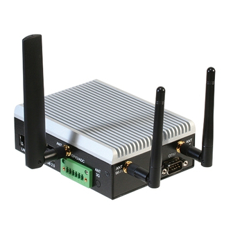
2.1.1 I/O Location HDMI USB 3.0 Power 5V DC Chapter 2 – Hardware Information... - Page 20 Chapter 2 – Hardware Information...
-
Page 21: Jumpers And Connectors For The Up-Cht01
Jumpers and Connectors for the UP-CHT01 Chapter 2 – Hardware Information... -
Page 22: List Of Switches And Connectors For The Up-Cht01
List of Switches and Connectors for the UP-CHT01 Please refer to the table below for all of the board’s jumpers that you can configure for your application. Label Function Power Button RTC Battery Wafer USB 3.0 Micro Connector USB 2.0 1x10P Wafer USB Type A Connector 1 USB Type A Connector 2 CN10... - Page 23 Label Connector Type (TF) Push Button Switch.HCH.PTS-099 (TF) WAFER BOX 2P .180D.1.25mm.CATCH.1201-700-02S (TF) Micro USB 3.0 Conn.10P .90D.B-type.ATTEND.209E-BE01 (TF)Wafer Box.10P .90D.1.0mm.CATCH.1204-700-10RM (TF)USB CONNECTOR DUAL PORT.8P .TechBest.KS-002D-ANB(2.0)-L (TF)USB CONNECTOR DUAL PORT.8P .TechBest.KS-002D-ANB(2.0)-L CN10 (TF) RJ45.14P .90D.W/TF & LED.UDE.RB1-1A5BAK1A CN11 (TF)HDMI CONN.19P .90D(F).A TYPE.FOXCONN.QJ51191-LFB4-7F CN12 (TF) PIN HEADER.2*20P .180D.(M).2.54mm.DIP CN14...
-
Page 24: Power Button (Sw1)
2.3.1 Power Button (SW1) Position Function SW10 Power on SW11 (default) 2.3.2 RTC Battery Wafer (CN1) Signal +V_COIN_BAT 2.3.3 USB 3.0 Micro Connector (CN6) Signal Signal USB_VCC USB2_D- CROSSBAR_TX1_N USB2_D+ CROSSBAR_TX1_P USB2_ID Chapter 2 – Hardware Information... -
Page 25: Usb 2.0 X 10P Wafer (Cn7)
CROSSBAR_RX1_N CROSSBAR_RX1_P 2.3.4 USB 2.0 x 10P Wafer (CN7) Signal Signal USB_VCC USB_HSIC_P4_D+ USB_HSIC_P3_D- USB_HSIC_P3_D+ UART0_RXD UART0_TXD USB_VCC USB_HSIC_P4_D- Chapter 2 – Hardware Information... -
Page 26: Dual Usb Type A Connector 1 (Cn8)
2.3.5 Dual USB Type A Connector 1 (CN8) Signal Signal USB_VCC USB_VCC USB2_P1_D- USB2_P2_D- USB2_P1_D+ USB2_P2_D+ 2.3.6 Dual USB Type A Connector 2 (CN9) Signal Signal USB_VCC USB_VCC USB2_P3_D- USB_HSIC_P2_D- USB2_P3_D+ USB_HSIC_P2_D+ Chapter 2 – Hardware Information... -
Page 27: Lan Connector (Cn10)
2.3.7 RJ-45 LAN Connector (CN10) Signal Signal LAN1_MDI0+ LAN1_MDI2- LAN1_MDI0- LAN1_MDI3+ LAN1_MDI1+ LAN1_MDI3- LAN1_MDI1- LAN_ACTLEDP LAN1_MDI2+ LAN_ACTLEDN LAN1_MDI2- LAN_LINK100# LAN1_MDI2+ LAN_LINK1000# 2.3.8 HDMI Connector (CN11) Signal Signal DDI2_TX0_HDMI_DP+ DDI2_CLK_HDMI_DN- DDI2_TX0_HDMI_DN- HDMI_CEC_D Chapter 2 – Hardware Information... -
Page 28: Hat 40 Gpio Connector (Cn12)
DDI2_TX1_HDMI_DP+ DDI2_DDC_CLK DDI2_TX1_HDMI_DN- DDI2_DDC_DAT DDI2_TX2_HDMI_DP+ +5V_HDMI DDI2_TX2_HDMI_DN- DDI2_TYPE_C_HPD DDI2_CLK_HDMI_DP+ 2.3.9 HAT 40 GPIO Connector (CN12) Signal Signal 3V3 POWER 5V POWER GPIO0/I2C1_SDA 5V POWER GPIO1/I2C1_SCL GPIO2/ADC-INPUT GPIO15/UART_TX GPIO16/UART_RX GPIO3 GPIO17/I2S_CLK GPIO4 GPIO5 GPIO18 3V3 POWER GPIO19 GPIO6/SPI _MOSI GPIO7/SPI_MISO GPIO20 GPIO8/SPI_CLK GPIO21/SPI_CS0N GPIO22/SPI_CS1N... -
Page 29: Reset Pin Header (Cn14)
GPIO11 GPIO24/PWM0 GPIO12/PWM1 GPIO13/I2S_FRM GPIO25 GPIO14 GPIO26/I2S_DATAIN GPIO27/I2S_DATAOUT 2.3.10 Reset Pin Header (CN14) Signal PMU_RSTBTN_N 2.3.11 DC Jack (CN30) Signal Chapter 2 – Hardware Information... -
Page 30: Mipi Dsi Connector (Cn31)
2.3.12 MIPI DSI Connector (CN31) Signal Signal Signal MDSI_A_DATA1_DN DDI0_TX0_DP DDI0_HPD_CONN MDSI_A_DATA1_DP DDI0_TX0_DN DDI0_BKLT_R_CTRL DDI0_VDD_EN MDSI_A_CLK_DN DDI0_TX1_DP DDI0_BKLT_EN MDSI_A_CLK_DP DDI0_TX1_DN MDSI_A_DATA0_DN DDI0_TX2_DP +3.3V MDSI_A_DATA0_DP DDI0_TX2_DN +3.3V +3.3V I2C2_3P3_SCL DDI0_TX3_DP +3.3V I2C2_3P3_SDA DDI0_TX3_DN +3.3V DDI1_DDC_C_CLK DDI0_AUX_DP DDI1_DDC_C_DAT DDI0_AUX_DN Chapter 2 – Hardware Information... -
Page 31: Mipi Csi Connector (Cn32)
2.3.13 MIPI CSI Connector (CN32) Signal Signal MCSI_1_DATA1_DN CAM_MCLK MCSI_1_DATA1_DP I2C2_SOC_SCL MCSI_1_CLK_DN I2C2_SOC_SDA MCSI_1_CLK_DP CAM_RST_N FLASH_RESET_N MCSI_1_DATA0_DN +2.8V MCSI_1_DATA0_DP GND_CAM +1.2V +1.8V 2.3.14 Power Button Wafer (CN33) Signal PWR_SW#_CTL_R Chapter 2 – Hardware Information... -
Page 32: Update Cpld Header (Cn34)
2.3.15 Update CPLD Header (CN34) Signal Signal CHT_GPIO_TMS CPLD_TMS CHT_GPIO_TDI CPLD_TDI CHT_GPIO_TCK CPLD_TCK CHT_GPIO_TDO CPLD_TDO FAN_PWM +1.8V Chapter 2 – Hardware Information... -
Page 33: Jumpers And Connectors For The Up-3Ghat01
Jumpers and Connectors for the UP-3GHAT01 Chapter 2 – Hardware Information... -
Page 34: List Of Switches And Connectors For The Up-3Ghat01
List of Switches and Connectors for the UP-3GHAT01 Please refer to the table below for all of the board’s jumpers that you can configure for your application. Label Function Connector Type 222-97-03GBE1 RS-232/422/485 Select Header 222-97-03GBE1 RS-232/422/485 Select Header 22Y8242-14D10B-01G Wifi pin7 Header 22N8561-04R10B-01G BT pin4 Header... -
Page 35: Wifi Header (Cn1)
2.5.2 Wifi Header (CN1) Signal Signal USB2_WF_TX USB2_WF_TX WF_PWM WF_PWM USB2_WF_DN_L USB2_WF_DN_L USB2_WF_PN_L USB2_WF_PN_L USB2_WF_LED# USB2_WF_LED# 2.5.3 BT Header (CN2) Signal BT_PWM USB2_BT_DN_L USB2_BT_PN_L 2.5.4 5V IN Header (HAT1) Signal Signal +3.3V HAT_TXD HAT_RXD Chapter 2 – Hardware Information... -
Page 36: Usb 2.0 Header (Usb1)
G_LED Y_LED +3.3V 2.5.5 USB 2.0 Header (USB1) Signal USB_VCC USB2_D- USB2_D+ USB_VCC USB2_D- USB2_D+ UART0_RXD Chapter 2 – Hardware Information... -
Page 37: Rs-232/422/485 Db9 Connector (Com1)
UART0_TXD 2.5.6 RS-232/422/485 DB9 Connector (COM1) Signal DCDA / RS422TX- / RS485- RXA / RS422TX+ / RS485+ TXA / RS422RX+ DTRA / RS422RX- DSRA RTSA CTSA 2.5.7 RS-232/422/485 Connector (COM2) Signal DCDB / RS422TX- / RS485- RXB / RS422TX+ / RS485+ TXB / RS422RX+ DTRB / RS422RX- DSRB... -
Page 38: Sim Card Connector (Sim1)
2.5.8 SIM Card Connector (SIM1) Signal Description Signal Description P_UIM_PWRF P_UIM_RSTC P_UIM_DATC P_UIM_CLKC P_UIM_VPPC GND_UIM 2.5.9 Mini PCIe Connector (MINI1) Signal Signal P3V_3G P_UIM_PWR P_UIM_DAT P_UIM_CLK P_UIM_RST P_UIM_VPP 3G_EN 3G_RST P3V_3G Chapter 2 – Hardware Information... - Page 39 USB2_HUB1_P1_DN USB2_HUB1_P1_DP WLAN_LED WLAN_LED WLAN_LED P3V_3G Chapter 2 – Hardware Information...
-
Page 40: 2.5.10 Gpio/Adc Connector Pin Assignments
2.5.10 GPIO/ADC Connector Pin Assignments Signal Description ADC(HAT40 ADC0/GPIO2) GPIO1(HAT40 GPIO10) GPIO2(HAT40 GPIO14) GPIO3(HAT40 GPIO25) Remark: If you want to control the CPLD function, please refer to the information in this link: https://wiki.up-community.org/Ubuntu Chapter 2 – Hardware Information... -
Page 41: Chapter 3 - Drivers Installation
Chapter 3 Chapter 3 – Drivers Installation... -
Page 42: Driver Download And Installation
Driver Download and Installation Step 1 Basic setup of the system and accessories Please make sure the following items are properly connected The power adapter in 3A-4A@5V. 5.5/2.1mm DC is properly connected with the system and power outlet The HDMI cable in type A male connector is properly connected with the system and display The keyboard &... - Page 43 Remark : Please noted that the MS Windows license is not included; you can buy a license from the Microsoft Store or from your sales representative. Step 2.2 Please use the following link to download a driver for the Windows 10 operating system https://downloads.up-community.org/download/microsoft-windows-10-64-bit-drivers/ Remark: Windows 10 drivers installation guides are available at:...
- Page 44 https://up-shop.org/up-peripherals/119-bluetooth-kit-for-up.html?search_query=wifi&r esults=17 to download Bluetooth driver Step 4.3 Download 3G/4G module driver 3G module driver https://up-shop.org/home/99-mpcie-3g-module-kit.html?search_query=+4G+module &results=20 4G module driver Please contact your sales representative for a link to download 4G module driver Chapter 3 – Driver Installation...
Need help?
Do you have a question about the Aaeon AIOT-IGWS01 and is the answer not in the manual?
Questions and answers