
Related Manuals for Netgate 8300


Summary of Contents for Netgate 8300
- Page 1 Secure Router Manual Netgate 8300 © Copyright 2024 Rubicon Communications LLC Aug 15, 2024...
-
Page 2: Table Of Contents
OUT OF THE BOX 1 Getting Started 2 Input and Output Ports 3 Connecting to the Console Port 4 Intelligent Platform Management Interface (IPMI) 5 Updating the Baseboard Management Controller Firmware 6 Re-arm the Chassis Intrusion Switch 7 M.2 NVMe SSD Installation 8 Add-On Expansion Card Installation 9 Additional Resources 10 Warranty and Support... - Page 3 Secure Router Manual Netgate 8300 This Quick Start Guide covers the first time connection procedures for the Netgate® 8300 Secure Router and also provides information necessary to keep the appliance up and running. © Copyright 2024 Rubicon Communications LLC...
-
Page 4: Getting Started
CHAPTER GETTING STARTED Use the following steps to configure the TNSR Secure Router. 1. To configure the Network Interfaces and gaining access to the Internet, follow the instructions provided in the Zero-to-Ping documentation. Note: Not all steps in the Zero-to-Ping documentation will be necessary for every configuration scenario. 2. -
Page 5: Front Panel
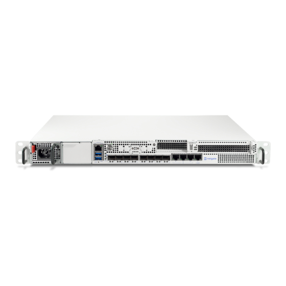
INPUT AND OUTPUT PORTS 2.1 Front Panel The front panel of the Netgate 8300 contains several items of interest for connecting to and managing the device. Fig. 1: Front view of the Netgate 8300 Security Gateway with key items numbered... - Page 6 Secure Router Manual Netgate 8300 Serial Console Port (2) Clients can access the serial console using the “Cisco” style console port with a separate cable and USB RJ45 serial adapter or client hardware port. Note: The RJ45 Serial Console port is only for use with the Serial Console. It cannot be used for any other purpose.
- Page 7 2.5 Gbps 2.1.2 Networking Ports with Add-on Cards There are two add-on expansion card slots on the Netgate 8300 device and they can both be populated with network cards, for a total of either two or four additional network ports.
-
Page 8: Status Leds
Netgate 8300 2.2 Status LEDs The Netgate 8300 has two groups of status LEDs: Three LEDs (including the power button) for the operating system status, and one LED for the baseboard management controller (BMC) status. Fig. 2: Close-up view of the Netgate 8300 Security Gateway Status LEDs The Operating System status LEDs are labeled with shapes which correspond to each LED: Green Circle, Blue Square, and Black Diamond. -
Page 9: Rear Panel
The rear panel of the device has items which are not meant to be accessed as often as the front, as the device is intended to be mounted in a rack. Fig. 3: Rear view of the Netgate 8300 Security Gateway with key items numbered When multiple PSUs are installed. - Page 10 Secure Router Manual Netgate 8300 The items below are marked with numbers on figure Rear view of the Netgate 8300 Security Gateway with key items numbered: Item Description Fan exhaust grills Ground connection Power switch © Copyright 2024 Rubicon Communications LLC...
-
Page 11: Connecting To The Console Port
3.1 Connecting to IPMI Web Browser Serial Console The IPMI interface on the Netgate 8300 contains a web-based serial console accessible via browser. This client is HTML-based and does not require extra software, only a current web browser. - Page 12 A separate adapter is required to make a connection between a computer and the firewall using the RJ45 serial port. The Netgate 8300 device ships with a USB A to RJ45 console cable suitable for this purpose. Fig. 1: Serial cable connected to RJ45 Console Port Any compatible cable may be used instead of the one shipped with the device.
- Page 13 Secure Router Manual Netgate 8300 3.4 Launch a Terminal Program Use a terminal program to connect to the system console port. Some choices of terminal programs: Windows For Windows the best practice is to run or SecureCRT. An example of how to configure PuTTY is PuTTY in Windows below.
- Page 14 Secure Router Manual Netgate 8300 Fig. 2: An example of using PuTTY in Windows © Copyright 2024 Rubicon Communications LLC...
- Page 15 Secure Router Manual Netgate 8300 Fig. 3: An example of using PuTTY in Linux GNU screen In many cases screen may be invoked simply by using the proper command line, where <console-port> is the console port that was located above.
-
Page 16: Terminal Settings
Secure Router Manual Netgate 8300 3.4.2 Terminal Settings The settings to use within the terminal program are: Speed 115200 baud, the speed of the BIOS Data bits Parity None Stop bits Flow Control Off or XON/OFF. Warning: Hardware flow control (RTS/CTS) must be disabled. -
Page 17: What's Next
Some devices expose multiple ports, so using the incorrect port may lead to no output or unexpected output. Hardware Failure There could be a hardware failure preventing the serial console from working. Contact Netgate TAC for assis- tance. 3.6.2 No Serial Output... - Page 18 Secure Router Manual Netgate 8300 Wrong Terminal Settings Ensure the terminal program is configured for the correct speed. The default BIOS speed is 115200, and many other modern operating systems use that speed as well. Some older operating systems or custom configurations may use slower speeds such as 9600 or 38400.
- Page 19 Secure Router Manual Netgate 8300 Character Encoding Ensure the terminal program is configured for the proper character encoding, such as UTF-8 or Latin-1, depend- ing on the operating system. (See Screen) 3.6.5 Serial Output Stops After the BIOS If serial output is shown for the BIOS but stops afterward, check the following items: Terminal Speed Ensure the terminal program is configured for the correct speed for the installed operating system.
-
Page 20: Intelligent Platform Management Interface (Ipmi)
FOUR INTELLIGENT PLATFORM MANAGEMENT INTERFACE (IPMI) The Netgate 8300 appliance includes a baseboard management controller (BMC) for out-of-band (OOB) access via Intelligent Platform Management Interface (IPMI). Administrators can use this interface to control the hardware itself, such as power on/off, access a serial over LAN (SOL) console, mount virtual media for installation, see hardware status events, and more. - Page 21 4.2 Default IPMI Credentials The default IPMI username is root and the default password is root. In compliance with privacy legislation, the Username and Password to access the IPMI port on the Netgate 8300 must be changed on first access.
- Page 22 Secure Router Manual Netgate 8300 Fig. 1: IPMI Web Console forcing a password change on first login © Copyright 2024 Rubicon Communications LLC...
- Page 23 Secure Router Manual Netgate 8300 4.4 Changing the IPMI Password The IPMI password for Netgate 8300 appliances can be changed either through the browser-based IPMI console or by using the ipmitool utility. 4.4.1 Using IPMI Web Console To change the IPMI password in the web console: •...
- Page 24 Secure Router Manual Netgate 8300 Note: If the username is not known, see the next section for information on how to use ipmitool to view the current user list. • Navigate to Configuration > Users Fig. 3: Configuration > Users •...
- Page 25 These commands may be performed from the TNSR CLI (host shell sudo <command>) or a shell prompt (sudo <command>). The following steps assumine the procedure is being performed locally on the Netgate 8300 from a shell prompt. © Copyright 2024 Rubicon Communications LLC...
- Page 26 Secure Router Manual Netgate 8300 Fig. 5: Modify User Form Fig. 6: Click Confirm © Copyright 2024 Rubicon Communications LLC...
- Page 27 NO ACCESS Warning: Usernames are case-sensitive. • Reset the password for a user The default root user is User ID 2, and the example below sets the password for this user to NETGATE. sudo ipmitool user password NETGATE Warning: This password is for example purposes only. Use a secure password.
- Page 28 These commands may be performed from the TNSR CLI (host shell sudo <command>) or a shell prompt (sudo <command>). The following steps assumine the procedure is being performed locally on the Netgate 8300 from a shell prompt. Note: To reach a shell prompt in TNSR, use the host shell command.
-
Page 29: Updating The Baseboard Management Controller Firmware
UPDATING THE BASEBOARD MANAGEMENT CONTROLLER FIRMWARE Occasionally there are updates to the Baseboard Management Controller (BMC) firmware on the Netgate 8300 to address problems or improve features. This firmware can be updated using the web interface on the BMC which also contains Intelligent Platform Management Interface (IPMI) functionality. -
Page 30: Connect To The Web Interface
Secure Router Manual Netgate 8300 5.3 Connect to the Web Interface This update is performed in the browser-based web interface on the BMC. To access this web interface, follow the directions in Intelligent Platform Management Interface (IPMI). Tip: As this update process requires a factory reset, make sure to note any customized settings before proceeding so they can be reconfigured after the update is complete. - Page 31 Secure Router Manual Netgate 8300 Fig. 2: Check the box to automatically reboot when the update finishes Fig. 3: Select the firmware update file (e.g. BMC_FW-Update.bin) © Copyright 2024 Rubicon Communications LLC...
- Page 32 Secure Router Manual Netgate 8300 Fig. 4: Firmware file upload in progress © Copyright 2024 Rubicon Communications LLC...
- Page 33 Secure Router Manual Netgate 8300 Fig. 5: Firmware update in progress © Copyright 2024 Rubicon Communications LLC...
- Page 34 Secure Router Manual Netgate 8300 Fig. 6: Click Update to perform the firmware update Fig. 7: Checking the BMC firmware version © Copyright 2024 Rubicon Communications LLC...
-
Page 35: Factory Reset
Secure Router Manual Netgate 8300 5.5 Factory Reset To complete the update, the BMC must be factory reset. Warning: This factory reset will remove any custom settings, including network configurations, additional users, and password changes. • Navigate to Diagnostics > Factory Reset. - Page 36 Secure Router Manual Netgate 8300 • Log back into the BMC web interface with the default credentials and change the password. When logging back in after the factory reset, use the default credentials and change the password as Tip: described in Intelligent Platform Management Interface (IPMI).
-
Page 37: Re-Arm The Chassis Intrusion Switch
CHAPTER RE-ARM THE CHASSIS INTRUSION SWITCH The chassis on Netgate 8300 has an intrusion detection function. If the chassis has been opened the intrusion switch will be tripped even if the power was off. Note: Chassis intrusion switch events and the current status of the sensor can be viewed in the IPMI web interface... -
Page 38: M.2 Nvme Ssd Installation
SEVEN M.2 NVME SSD INSTALLATION The Netgate® 8300 ships with one PCIe-based M.2 NVMe SSD. Optionally, a second PCIe-based M.2 NVMe drive can be installed as an upgrade. Note: This guide assumes a second disk is being added for redundancy via software RAID disk mirroring. -
Page 39: Required Tools And Hardware
Installing the SSD requires removing the top of the case to expose the internal components. For safety, before opening the case, the Netgate 8300 must be completely disconnected from everything. This includes power, network cables, USB cables, serial console cables, and any other external cables or devices connected to the Netgate 8300. Danger: Reminder: •... - Page 40 3. Unplug all network cables, USB cables and devices, serial console connections, etc. 4. Dismount the Netgate 8300 from the rack 5. Move the Netgate 8300 to a safe work location such as an anti-static mat © Copyright 2024 Rubicon Communications LLC...
- Page 41 Secure Router Manual Netgate 8300 Fig. 2: Power Supply Units with power receptacles circled and status LEDs indicated with arrows © Copyright 2024 Rubicon Communications LLC...
- Page 42 Secure Router Manual Netgate 8300 7.3.4 Removing the Lid The next portion of the procedure involves opening the device and removing the lid. Danger: Reminder: • Anti-static protection must be used throughout this procedure. • Any hardware damage incurred during this procedure is not covered by the hardware warranty.
- Page 43 Secure Router Manual Netgate 8300 Fig. 4: Screw on the rear side of the unit at the left top corner, indicated with an arrow. © Copyright 2024 Rubicon Communications LLC...
- Page 44 Secure Router Manual Netgate 8300 Fig. 5: Screw on the rear side of the unit at the right top corner, indicated with an arrow. © Copyright 2024 Rubicon Communications LLC...
- Page 45 Secure Router Manual Netgate 8300 Fig. 6: Sliding back the top cover away from the front panel © Copyright 2024 Rubicon Communications LLC...
- Page 46 Secure Router Manual Netgate 8300 Fig. 7: Top cover in position to be lifted off © Copyright 2024 Rubicon Communications LLC...
- Page 47 Secure Router Manual Netgate 8300 Fig. 8: Screw holding the fan duct in place, indicated with an arrow © Copyright 2024 Rubicon Communications LLC...
- Page 48 • Any hardware damage incurred during this procedure is not covered by the hardware warranty. 1. Turn the riser card over so the second M.2 slot is visible. Note: As mentioned earlier in this document, the Netgate 8300 currently supports M.2 B+M-Key or M-Key PCIe NVMe SSDs in 2280 or 2242 sizes.
- Page 49 Secure Router Manual Netgate 8300 Fig. 9: Fan duct lifted out of the way to access the M.2 NVMe riser © Copyright 2024 Rubicon Communications LLC...
- Page 50 Secure Router Manual Netgate 8300 Fig. 10: M.2 NVMe riser card clips (circled) in the closed position Fig. 11: M.2 NVMe riser card clips in the open position Fig. 12: M.2 NVMe riser card slot 1 with the stock SSD installed...
- Page 51 Secure Router Manual Netgate 8300 Fig. 13: M.2 NVMe riser card slot 2 (empty) and add-on M.2 NVMe SSD before install © Copyright 2024 Rubicon Communications LLC...
- Page 52 Secure Router Manual Netgate 8300 Warning: M.2 cards are keyed. Do not force an M.2 card into a slot with mismatched keying. Refer to M.2 Edge Connector Keying for a depiction of the different M.2 key types. 4. Gently push down the M.2 NMVe card until it snaps into place against the retaining clip.
- Page 53 Secure Router Manual Netgate 8300 Fig. 15: Close-up view of the M.2 retaining clip for slot 2 with the SSD secured © Copyright 2024 Rubicon Communications LLC...
- Page 54 Secure Router Manual Netgate 8300 Fig. 16: Replacing the M.2 riser card © Copyright 2024 Rubicon Communications LLC...
- Page 55 Secure Router Manual Netgate 8300 Fig. 17: M.2 riser card with two SSDs and riser clips in the closed position © Copyright 2024 Rubicon Communications LLC...
- Page 56 Secure Router Manual Netgate 8300 7.3.9 Replacing and Fastening the Lid With the internal components all in place, the next step is to replace the lid and all its fasteners. Danger: Reminder: • Anti-static protection must be used throughout this procedure.
- Page 57 Secure Router Manual Netgate 8300 Fig. 19: Slide the top cover back toward the front panel © Copyright 2024 Rubicon Communications LLC...
- Page 58 Secure Router Manual Netgate 8300 Fig. 20: Screw on the rear side of the unit at the left top corner, indicated with an arrow. © Copyright 2024 Rubicon Communications LLC...
- Page 59 Secure Router Manual Netgate 8300 Fig. 21: Screw on the rear side of the unit at the right top corner, indicated with an arrow. © Copyright 2024 Rubicon Communications LLC...
- Page 60 7.3.10 Reconnect The device is now ready to be put back into its former location. 1. Mount the Netgate 8300 in the rack 2. Plug in all network cables, USB cables and devices, serial console connections, etc. 3. Insert the USB memstick containing the installation media 4.
- Page 61 Secure Router Manual Netgate 8300 Fig. 23: Power Supply Units with power receptacles circled and status LEDs indicated with arrows © Copyright 2024 Rubicon Communications LLC...
-
Page 62: Restore The Configuration
Secure Router Manual Netgate 8300 7.3.12 Restore the Configuration If a configuration was procedure, now is the time to restore the configuration using the method backed up earlier in this described in the TNSR software documentation section on Backup and Restore. -
Page 63: Add-On Expansion Card Installation
CHAPTER EIGHT ADD-ON EXPANSION CARD INSTALLATION The Netgate® 8300 has two expansion card slots available for additional devices such as 25 Gbit/s or 100 Gbit/s network interface cards. The two expansion card slots have the following capabilities: • 1x PCIe 3.0 x8 LP (Low Profile) slot which supports half-length low profile cards. - Page 64 Installing an add-on expansion card requires removing the top of the case to expose the internal components. For safety, before opening the case, the Netgate 8300 must be completely disconnected from everything. This includes power, network cables, USB cables, serial console cables, and any other external cables or devices connected to the Netgate 8300.
- Page 65 Secure Router Manual Netgate 8300 Fig. 1: Power switch (circled) in the off position © Copyright 2024 Rubicon Communications LLC...
- Page 66 Secure Router Manual Netgate 8300 Fig. 2: Power Supply Units with power receptacles circled and status LEDs indicated with arrows © Copyright 2024 Rubicon Communications LLC...
- Page 67 Secure Router Manual Netgate 8300 8.3.3 Removing the Lid The next portion of the procedure involves opening the device and removing the lid. Danger: Reminder: • Anti-static protection must be used throughout this procedure. • Any hardware damage incurred during this procedure is not covered by the hardware warranty.
- Page 68 Secure Router Manual Netgate 8300 Fig. 4: Screw on the rear side of the unit at the left top corner, indicated with an arrow. © Copyright 2024 Rubicon Communications LLC...
- Page 69 Secure Router Manual Netgate 8300 Fig. 5: Screw on the rear side of the unit at the right top corner, indicated with an arrow. © Copyright 2024 Rubicon Communications LLC...
- Page 70 Secure Router Manual Netgate 8300 Fig. 6: Sliding back the top cover away from the front panel © Copyright 2024 Rubicon Communications LLC...
- Page 71 Secure Router Manual Netgate 8300 Fig. 7: Top cover in position to be lifted off © Copyright 2024 Rubicon Communications LLC...
- Page 72 Secure Router Manual Netgate 8300 Note: These screws are captive and will not fully remove from the riser assembly. It is sufficient to loosen the screws until they no longer attach the riser assembly to the motherboard. This may be felt as a soft “click” when the screw is freely rotating and the threads are not engaged.
- Page 73 Secure Router Manual Netgate 8300 Fig. 9: Location of the riser assembly retaining screw on the front of the unit indicated with a red circle Fig. 10: Lift the riser assembly from the rear to remove it from the riser slot on the motherboard...
- Page 74 Secure Router Manual Netgate 8300 Fig. 11: Lift and rotate the riser assembly from the front as indicated by the red arrow to remove it from the chassis © Copyright 2024 Rubicon Communications LLC...
- Page 75 Secure Router Manual Netgate 8300 8.3.5 Install the Add-on Expansion Card With the riser assembly removed, it is time to install the add-on expansion card. Danger: Reminder: • Anti-static protection must be used throughout this procedure. • Any hardware damage incurred during this procedure is not covered by the hardware warranty.
- Page 76 Secure Router Manual Netgate 8300 Fig. 13: Location of the low profile add-on expansion card slot retaining screw indicated with a red circle © Copyright 2024 Rubicon Communications LLC...
- Page 77 Secure Router Manual Netgate 8300 Fig. 14: Location of the full height add-on expansion card slot retaining screw indicated with a red circle Fig. 15: Slide the expansion slot cover away from the center of the riser assembly © Copyright 2024 Rubicon Communications LLC...
- Page 78 Secure Router Manual Netgate 8300 Fig. 16: Remove the expansion slot cover once it is free from the expansion slot The rear of the socket has a retention clip to hold the card in place which should be engaged once the card is fully...
- Page 79 Secure Router Manual Netgate 8300 Fig. 17: Installing an add-on network interface card into an expansion slot © Copyright 2024 Rubicon Communications LLC...
- Page 80 Secure Router Manual Netgate 8300 Fig. 18: Expansion card slot retention clip holding a card in place © Copyright 2024 Rubicon Communications LLC...
- Page 81 Secure Router Manual Netgate 8300 Fig. 19: Expansion card aligned with the riser assembly and retention screw hole © Copyright 2024 Rubicon Communications LLC...
- Page 82 Secure Router Manual Netgate 8300 Fig. 20: Expansion card fastened in the riser assembly using the retention screw © Copyright 2024 Rubicon Communications LLC...
- Page 83 Secure Router Manual Netgate 8300 Fig. 21: Rotate and replace the riser assembly from the front in the opposite direction indicated by the red arrow © Copyright 2024 Rubicon Communications LLC...
- Page 84 Secure Router Manual Netgate 8300 Fig. 22: Re-seat the riser assembly in the the riser slot from the rear of the motherboard in the opposite of the direction indicated by the red arrow Fig. 23: Location of the riser assembly retaining screw on the front of the unit indicated with a red circle...
- Page 85 Secure Router Manual Netgate 8300 Fig. 24: Location of the captive riser assembly retaining screws indicated with red circles © Copyright 2024 Rubicon Communications LLC...
- Page 86 Secure Router Manual Netgate 8300 8.3.7 Replacing and Fastening the Lid With the internal components all in place, the next step is to replace the lid and all its fasteners. Danger: Reminder: • Anti-static protection must be used throughout this procedure.
- Page 87 Secure Router Manual Netgate 8300 Fig. 26: Slide the top cover back toward the front panel © Copyright 2024 Rubicon Communications LLC...
- Page 88 Secure Router Manual Netgate 8300 Fig. 27: Screw on the rear side of the unit at the left top corner, indicated with an arrow. © Copyright 2024 Rubicon Communications LLC...
- Page 89 Secure Router Manual Netgate 8300 Fig. 28: Screw on the rear side of the unit at the right top corner, indicated with an arrow. © Copyright 2024 Rubicon Communications LLC...
- Page 90 8.3.8 Reconnect The device is now ready to be put back into its former location. 1. Mount the Netgate 8300 in the rack 2. Plug in all network cables, USB cables and devices, serial console connections, etc. 3. Insert the USB memstick containing the installation media 4.
- Page 91 Secure Router Manual Netgate 8300 Fig. 30: Power Supply Units with power receptacles circled and status LEDs indicated with arrows © Copyright 2024 Rubicon Communications LLC...
- Page 92 Secure Router Manual Netgate 8300 8.3.10 Re-arm the Intrusion Sensor Opening the case to install the expansion card will trigger the intrusion alarm sensor, even while the device is removed from power. The intrusion alarm causes the fans to run at a higher fixed speed until the sensor is re-armed.
-
Page 93: Professional Services
Netgate training has got you covered. https://www.netgate.com/training/ 9.3 Resource Library To learn more about how to use your Netgate appliance and for other helpful resources, make sure to browse our Resource Library. https://www.netgate.com/resources/... -
Page 94: Warranty And Support
CHAPTER WARRANTY AND SUPPORT • One year manufacturer’s warranty. • Please contact Netgate for warranty information or view the Product Lifecycle page. • All Specifications subject to change without notice. Enterprise Support is included with an active software subscription, for more information view the...
Need help?
Do you have a question about the 8300 and is the answer not in the manual?
Questions and answers