Advertisement
Quick Links
Exfo FVA-3100-DEI
Variable Attenuator
A l l t r a d e m a r k s , b r a n d n a m e s , a n d b r a n d s a p p e a r i n g h e r e i n a r e t h e p r o p e r t y o f t h e i r r e s p e c t i v e o w n e r s .
• C r i t i c a l a n d e x p e d i t e d s e r v i c e s
• I n s t o c k / R e a d y - t o - s h i p
Artisan Scientific Corporation dba Artisan Technology Group is not an affiliate, representative, or authorized distributor for any manufacturer listed herein.
$
3495
.00
In Stock
Qty Available: 1
Used and in Excellent Condition
Buy Today!
https://www.artisantg.com/55304-7
• We b u y y o u r e x c e s s , u n d e r u t i l i z e d , a n d i d l e e q u i p me n t
• F u l l - s e r v i c e , i n d e p e n d e n t r e p a i r c e n t e r
Advertisement

Subscribe to Our Youtube Channel
Related Manuals for EXFO FVA-3100-DEI


Summary of Contents for EXFO FVA-3100-DEI
- Page 1 Exfo FVA-3100-DEI Variable Attenuator 3495 In Stock Qty Available: 1 Used and in Excellent Condition Buy Today! https://www.artisantg.com/55304-7 A l l t r a d e m a r k s , b r a n d n a m e s , a n d b r a n d s a p p e a r i n g h e r e i n a r e t h e p r o p e r t y o f t h e i r r e s p e c t i v e o w n e r s .
- Page 2 Tel.: +65 6333 8241 · Fax: +65 6333 8242 User Guide TOLL-FREE (USA and Canada) 1 800 663-3936 www.exfo.com · info@exfo.com © 2003 EXFO Electro-Optical Engineering Inc. All rights reserved. Printed in Canada. Artisan Technology Group - Quality Instrumentation ... Guaranteed | (888) 88-SOURCE | www.artisantg.com...
- Page 3 Tel.: +65 6333 8241 · Fax: +65 6333 8242 User Guide TOLL-FREE (USA and Canada) 1 800 663-3936 www.exfo.com · info@exfo.com © 2003 EXFO Electro-Optical Engineering Inc. All rights reserved. Printed in Canada. Artisan Technology Group - Quality Instrumentation ... Guaranteed | (888) 88-SOURCE | www.artisantg.com...
- Page 4 Variable Attenuator FVA-3100 User Guide If the equipment described herein bears the symbol, the said equipment complies with the P/N: 1036215 applicable European Union October 2002 Directive and Standards mentioned in the Declaration of Conformity. Artisan Technology Group - Quality Instrumentation ... Guaranteed | (888) 88-SOURCE | www.artisantg.com...
- Page 5 Engineering Inc. (EXFO). Information provided by EXFO is believed to be accurate and reliable. However, no responsibility is assumed by EXFO for its use nor for any infringements of patents or other rights of third parties that may result from its use.
-
Page 6: Table Of Contents
Saving and Recalling a Configuration ...................35 5 Operating Your Variable Attenuator ............39 Connecting Optical Fibers .....................39 Installing the EXFO Universal Interface (EUI) .................40 Performing an Attenuation Routine ..................41 Operating the Shutter ......................49 6 Controlling Your Variable Attenuator Remotely ........51 Setting Up the Variable Attenuator for Remote Control ............51... - Page 7 Cleaning Connectors Equipped with EUI/EUA Adapters ............62 Cleaning Fixed Connectors ....................66 Cleaning Detector Ports ......................68 Recalibrating the Unit ......................69 8 Troubleshooting ..................71 Finding Information on the EXFO Web Site ................71 Contacting the Technical Support Group ................72 Transportation ........................73 9 Warranty ......................75 General Information ......................75 Liability ..........................76...
-
Page 8: Certification Information
This unit has undergone extensive testing according to the European Union Directive and Standards. All pre-qualification tests were performed internally, at EXFO, while all final tests were performed externally, at an independent, accredited laboratory. This guarantees the unerring objectivity and authoritative compliance of all test results. - Page 9 Certification Information MPORTANT Use of shielded remote I/O cables, with properly grounded shields and metal connectors, is recommended in order to reduce radio frequency interference that may emanate from these cables. MPORTANT The AC adapter provided with this product is equipped with a shielded three-wire power cord and plug.
- Page 10 Certification Information DECLARATION OF CONFORMITY Application of Council Directive(s): 73/23/EEC - The Low Voltage Directive 89/336/EEC - The EMC Directive Manufacturer’s Name: EXFO ELECTRO-OPTICAL ENG. Manufacturer’s Address: 465 Godin Avenue Vanier, Quebec Canada G1M 3G7 (418) 683-0211 Equipment Type/Environment: Industrial Scientific Equipment Trade Name/Model No.:...
- Page 11 Artisan Technology Group - Quality Instrumentation ... Guaranteed | (888) 88-SOURCE | www.artisantg.com...
-
Page 12: Introducing The Fva-3100 Variable Attenuator
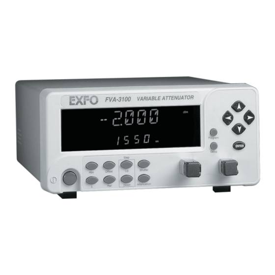
Introducing the FVA-3100 Variable Attenuator Main Features The FVA-3100 Variable Attenuator is the instrument that allows you to perform several attenuation related tasks. The FVA-3100 Variable Attenuator is configured for singlemode and multimode fibers. It is built to offer a high spectral uniformity, an important feature which allows you to maintain the attenuation value throughout the entire WDM spectrum. -
Page 13: Front Panel
Introducing the FVA-3100 Variable Attenuator Front Panel Front Panel Program menu access Display Arrow buttons for Setup menu access menu navigation and parameter setting FVA-3100 VARIABLE ATTENUATOR Offset mode access Program ENTER Absolute mode access Setup Step Offset Shutter Shutter On/off button λ... -
Page 14: Back Panel
Introducing the FVA-3100 Variable Attenuator Back Panel Back Panel Serial port (RS-232 DTE) Fuse holder Power inlet GPIB port MODEL: GO Serial Port GPIB IEEE 488.2 LR107723 100-240 V 50/60 Hz F2AL250 V SH1, AH1, T6, L4, SR1, RL1, PP0, DC1, DT1, C0, E2 This device complies with part 15 of the FCC rules. -
Page 15: Available Models
Introducing the FVA-3100 Variable Attenuator Available Models Available Models According to the models you own, additional options are available. The FVA-3100-BM and FVA-3100-BMW offer spectral uniformity and maintain constant attenuation values. The FVA-3100-BM, FVA-3100-BMW, FVA-3100-DM all come with a monitor output, which ensures accurate power-level monitoring. -
Page 16: Main Concept
Main Concept The significance of the attenuation value displayed by an optical attenuator may differ from one manufacturer to another. At EXFO, for example, the attenuation displayed by the FVA-3100 Variable Attenuator is the actual loss or attenuation between the input and the output ports of the Variable Attenuator, including the loss of its own internal connectors, after performing a reference reading with a power meter. - Page 17 Artisan Technology Group - Quality Instrumentation ... Guaranteed | (888) 88-SOURCE | www.artisantg.com...
-
Page 18: Safety Information
Safety Information Safety Conventions You should understand the following conventions before using the product described in this manual: ARNING Refers to a potential personal hazard. It requires a procedure which, if not correctly followed, may result in bodily harm or injury. Do not proceed unless you understand and meet the required conditions. -
Page 19: Laser Safety Information
Safety Information Laser Safety Information Laser Safety Information ARNING Do not install or terminate fibers while a light source is active. Never look directly into a live fiber and ensure that your eyes are protected at all times. ARNING Use of controls, adjustments and procedures for operation and maintenance other than those specified herein may result in hazardous radiation exposure. - Page 20 Safety Information Electrical Safety Information ARNING To avoid electrical shock, do not operate the unit if there are signs of damage to any part of the outer surface (covers, panels, etc.). To avoid serious injury, observe the following precautions before powering on the unit.
- Page 21 Artisan Technology Group - Quality Instrumentation ... Guaranteed | (888) 88-SOURCE | www.artisantg.com...
-
Page 22: Getting Started With Your Variable Attenuator
Getting Started With Your Variable Attenuator Installing your FVA-3100 Variable Attenuator in a Rackmount You can place your FVA-3100 Variable Attenuator in a rackmount in order to facilitate its usage. To install the rackmount: 1. Fix the angle iron using four flat Phillips screws. 2. - Page 23 Getting Started With Your Variable Attenuator Installing your FVA-3100 Variable Attenuator in a Rackmount To install your FVA-3100 Variable Attenuator in a rackmount: 1. Slide the benchtop unit into the rackmount and tighten it from underneath using the four cover fixing screws. If measurement X on the illustration exceeds 11.125 in., fix the unit into the four holes identified as A.
-
Page 24: Turning The Variable Attenuator On And Off
Getting Started With Your Variable Attenuator Turning the Variable Attenuator On and Off Turning the Variable Attenuator On and Off When you turn on your unit: it beeps twice ➤ it performs a self-test, ➤ it enters the mode that was active at the last power-off (Absolute, ➤... -
Page 25: Accessing Menus
Getting Started With Your Variable Attenuator Accessing Menus To turn the unit on and off: Use the red button in the lower left corner of the front panel. MPORTANT Some internal mechanisms can sometimes take a few seconds to adjust, depending on the operation performed. While the Variable Attenuator is performing internal adjustments (for example after having changed the wavelength or the attenuation setting), no buttons should be pressed while Program flashes on the display. -
Page 26: Setting Up Your Variable Attenuator
Setting Up Your Variable Attenuator Selecting the Display Intensity Display intensity may be set to high or low. You can also turn off the display without turning off the unit. To select the display intensity: 1. Press on the Setup. Setup menu access FVA-3100 VARIABLE ATTENUATOR... - Page 27 Setting Up Your Variable Attenuator Selecting the Display Intensity 2. Use the left/right arrows to move until it displays DIMMER. 3. Press ENTER. The current dimmer state will start flashing. 4. Use the up/down arrows to modify the dimmer status: LO, HI, or OFF. Arrow buttons for menu navigation and parameter setting...
-
Page 28: Locking Control Key Access
Setting Up Your Variable Attenuator Locking Control Key Access 6. To exit the Setup menu, press on the Setup button. Locking Control Key Access To prevent unintended use of the FVA-3100 Variable Attenuator during operation, you can lock the control keys (the blue buttons on the front panel of the unit). - Page 29 Setting Up Your Variable Attenuator Locking Control Key Access The LOCKED message is briefly displayed, then the unit reverts to the settings that were active before you entered the Setup menu. All control keys are deactivated. To unlock the keypad: 1.
-
Page 30: Managing The Wavelength Shortlist
Setting Up Your Variable Attenuator Managing the Wavelength Shortlist Managing the Wavelength Shortlist The FVA-3100 Variable Attenuator can test at many wavelengths. The accepted wavelengths depend on the configuration of your unit. You can store the wavelengths you use most often in a shortlist so you can quickly access them. - Page 31 Setting Up Your Variable Attenuator Managing the Wavelength Shortlist 2. Use the left/right arrows to move until LAMBDA is displayed. 3. Use the up/down arrows to move until Add is displayed . 4. Press ENTER. A wavelength will be suggested and the first digit will flash.
- Page 32 Setting Up Your Variable Attenuator Managing the Wavelength Shortlist To delete a wavelength from the shortlist: 1. Press the Setup button. Arrow buttons for menu navigation Setup menu access and parameter setting FVA-3100 VARIABLE ATTENUATOR Program ENTER Absolute mode access Setup Step Offset...
- Page 33 Setting Up Your Variable Attenuator Managing the Wavelength Shortlist To delete all wavelengths from the shortlist: 1. Press the Setup button. 2. Press the left/right arrows until LAMBDA is displayed. 3. Press the up/down arrows until DEL ALL appears in the lower portion of the display.
-
Page 34: Selecting The Attenuation
Setting Up Your Variable Attenuator Selecting the Attenuation Selecting the Attenuation The attenuation can be set using two methods: By using the up and down arrows buttons, the attenuation is modified ➤ one step (up or down) at a time. By using the Attenuation button, you can quickly and precisely set the ➤... - Page 35 Setting Up Your Variable Attenuator Selecting the Attenuation To enter a specific attenuation value: 1. Press the Attenuation button. The first segment of the attenuation setting starts flashing. Attenuation setting Current wavelength 2. Enter a new attenuation value. Use the up/down arrows to change the flashing digit and the left/right arrows to activate the next digit.
- Page 36 The attenuation range (minimum and maximum possible attenuation) of your FVA-3100 Variable Attenuator depends on the model you have at hand. Although EXFO guarantees that the minimum insertion loss is below a specified value, it may vary slightly from one wavelength to another and from one variable attenuator to another.
- Page 37 Setting Up Your Variable Attenuator Selecting the Attenuation To set the maximum attenuation: 1. Select a wavelength by clicking on the wavelength control until you reach the desired wavelength. Arrow buttons for menu navigation Setup menu access and parameter setting FVA-3100 VARIABLE ATTENUATOR Program...
-
Page 38: Selecting And Using An Attenuation Display Mode
Setting Up Your Variable Attenuator Selecting and Using an Attenuation Display Mode Selecting and Using an Attenuation Display Mode Note: The total or absolute attenuation referred to in this manual is the actual optical insertion loss between the input and output ports, including the connectors. - Page 39 Using the above setup (i.e, light source, variable attenuator, and an accurately determined offset value), Exfo has created a precise variable light source with a dynamic range of nearly 100 dB. Note: You must define the appropriate B value for the operating wavelength before enabling X+B mode.
- Page 40 Setting Up Your Variable Attenuator Selecting and Using an Attenuation Display Mode To set Absolute attenuation mode: Press on the Abs button at any time to enable Absolute mode. Absolute attenuation Wavelength In Offset mode, the offset value is always displayed in the lower portion of the display while the upper portion (large digits) displays the sum of two values.
- Page 41 Setting Up Your Variable Attenuator Selecting and Using an Attenuation Display Mode To define an offset value for a specific wavelength: 1. Set the Variable Attenuator to the appropriate wavelength. 2. Choose Setup. Arrow buttons for menu navigation Setup menu access and parameter setting FVA-3100 VARIABLE ATTENUATOR...
- Page 42 Setting Up Your Variable Attenuator Selecting and Using an Attenuation Display Mode 4. Press ENTER. The first segment of the current offset value will start flashing. 5. Enter a new offset. Use the up/down arrows to change the flashing digit and the left/right arrows to activate the next digit.
- Page 43 Setting Up Your Variable Attenuator Selecting and Using an Attenuation Display Mode To use the offset mode: 1. Ensure that the display is in Absolute mode (choose Abs). 2. Select the appropriate wavelength by pressing the wavelength control until you reach the desired wavelength. 3.
- Page 44 Setting Up Your Variable Attenuator Selecting and Using an Attenuation Display Mode Relative attenuation Absolute attenuation If the attenuation is increased by 1.0 dB, the upper digits (relative attenuation) will display -1.00 dB and the lower digits (absolute attenuation) will indicate -17.45 dB. Variable Attenuator Artisan Technology Group - Quality Instrumentation ...
- Page 45 Setting Up Your Variable Attenuator Selecting and Using an Attenuation Display Mode To use the Reference mode: 1. Ensure that the display is in Absolute mode (choose Abs). Arrow buttons for menu Setup menu access navigation and parameter setting FVA-3100 VARIABLE ATTENUATOR Offset mode access Program...
-
Page 46: Saving And Recalling A Configuration
Setting Up Your Variable Attenuator Saving and Recalling a Configuration Saving and Recalling a Configuration Once the Variable Attenuator has been customized for a specific application or user, it is possible to save the configuration. Saved parameters are current wavelength and attenuation ➤... - Page 47 Setting Up Your Variable Attenuator Saving and Recalling a Configuration To save a configuration: 1. Customize the Variable Attenuator as required. 2. Press the Setup button. Arrow buttons for menu navigation Setup menu access and parameter setting FVA-3100 VARIABLE ATTENUATOR Program ENTER Setup...
- Page 48 Setting Up Your Variable Attenuator Saving and Recalling a Configuration 5. Press the up/down arrows to modify the configuration number. 6. Press ENTER. 7. Press on the Setup button to exit the menu. Once you have saved a configuration (see Saving and Recalling a Configuration on page 35), you can recall it at any time.
- Page 49 Setting Up Your Variable Attenuator Saving and Recalling a Configuration 2. Press the left/right arrows until RECALL is displayed. Configuration number 3. Press ENTER. The configuration number (bottom of the screen) will start flashing. 4. Use the up/down arrows to select the number of the configuration you want to recall.
-
Page 50: Operating Your Variable Attenuator
Operating Your Variable Attenuator Connecting Optical Fibers MPORTANT To ensure maximum output power and to avoid erroneous readings, always clean fiber ends as explained below before inserting them into the port. To connect the fiber-optic cable to the port: 1. Clean the fiber ends as follows: 1a. -
Page 51: Installing The Exfo Universal Interface (Eui)
Operating Your Variable Attenuator Installing the EXFO Universal Interface (EUI) Installing the EXFO Universal Interface (EUI) The EUI fixed baseplate is available for connectors with angled (APC) or non-angled (UPC) polishing. A green border around the baseplate indicates that it is for APC-type connectors, as shown below:... -
Page 52: Performing An Attenuation Routine
Operating Your Variable Attenuator Performing an Attenuation Routine Performing an Attenuation Routine You can program the FVA-3100 Variable Attenuator to perform an attenuation routine. Once the routine is started, the variable attenuator will automatically increase or decrease the inserted attenuation (by steps), return to the initial attenuation state, and perform the routine again until you stop it. - Page 53 Operating Your Variable Attenuator Performing an Attenuation Routine Switch to –11 dB attenuation for 10 seconds (step 1), ➤ Switch to –12 dB attenuation for 10 seconds (step 2), ➤ Switch to –13 dB attenuation for 10 seconds (step 3), and ➤...
- Page 54 Operating Your Variable Attenuator Performing an Attenuation Routine To program the attenuation routine: 1. Press on the Program button. Arrow buttons for menu Program menu access navigation and parameter setting FVA-3100 VARIABLE ATTENUATOR Program ENTER Setup Step Offset Shutter Shutter λ...
- Page 55 Operating Your Variable Attenuator Performing an Attenuation Routine 3. If you do not want the routine to be delayed, leave the delay at 000.00.00. 4. Once the delay is set, press ENTER. Hours Minutes Seconds 5. Select the duration (time for which the Variable Attenuator will remain at each step).
- Page 56 Operating Your Variable Attenuator Performing an Attenuation Routine 9. Press ENTER. The first digit will start flashing. Use the up/down arrows to change the flashing digit and the left/right arrows to activate the next digit. 10. Once the number of steps is set, press ENTER. 11.
- Page 57 Operating Your Variable Attenuator Performing an Attenuation Routine To start a routine: 1. Set the wavelength by pressing the wavelength control until you reach the desired wavelength. 2. Set the Variable Attenuator to the initial attenuation. 3. Press Program. Arrow buttons for menu Program menu access navigation and parameter settin FVA-3100...
- Page 58 Operating Your Variable Attenuator Performing an Attenuation Routine To know... perform the following steps how much time is Press Program left in the delay Press the left/right arrows until DELAY is displayed. how much time is Press Program left in the current Press the left/rigth arrows until DURATION is displayed.
- Page 59 Operating Your Variable Attenuator Performing an Attenuation Routine To stop the attenuation routine: 1. Press Program. 2. Press the left/right arrows until STOP is displayed. 3. Press ENTER. The routine completes the current attenuation step, then stops (Program disappears from the display). FVA-3100 Artisan Technology Group - Quality Instrumentation ...
-
Page 60: Operating The Shutter
Operating Your Variable Attenuator Operating the Shutter Operating the Shutter The optical shutter is an electro-mechanical device which, when activated, totally blocks light transmission. To block light transmission: Use the Shutter button to turn the shutter on or off. When the shutter is activated, Shutter On appears in the lower right portion of the display. - Page 61 Artisan Technology Group - Quality Instrumentation ... Guaranteed | (888) 88-SOURCE | www.artisantg.com...
-
Page 62: Controlling Your Variable Attenuator Remotely
Remote appears in the lower left corner of the display. Note: If you have already designed a GPIB program to control an attenuator from EXFO’s IQ Series (IQS-3100), you can reuse sections for the FVA-3100. Setting Up the Variable Attenuator for Remote... - Page 63 Controlling Your Variable Attenuator Remotely Setting Up the Variable Attenuator for Remote Control To select remote command mode: GPIB setting GPIB address 1. If you have select GPIB-RS as a command mode, you only need to set the address. 2. If you want to select the RS-232 mode, press ENTER. RS-232 setting 3.
- Page 64 Controlling Your Variable Attenuator Remotely Setting Up the Variable Attenuator for Remote Control To select a GPIB address: 1. Once you selected GPIB as a command mode, you can set the GPIB address you want. 2. Press ENTER. The bottom part of the displays will start flashing. 3.
-
Page 65: Communication Parameters
Controlling Your Variable Attenuator Remotely Communication Parameters Communication Parameters Note: EOS means End of String. EOI means End or Identify. For GPIB Communication Terminate Read on EOS Set EOI with EOS on Writes Type of comparison on EOS 8-bits EOS byte Sends EOI at end of Writes GPIB primary address GPIB secondary address... -
Page 66: Standard Status Data Structure
Controlling Your Variable Attenuator Remotely Standard Status Data Structure Standard Status Data Structure The following page illustrates the four common status and enable registers as defined by IEEE 488.2. This diagram is a useful aid in understanding the general commands and how a service request (SRQ) is generated. The four registers are: Standard Event Status Register (ESR) ➤... - Page 67 Controlling Your Variable Attenuator Remotely Standard Status Data Structure Standard Event Status Register (ESR) & & & & & & & & Standard Event Status Enable Register (ESE) Output Queue not Empty read by serial poll ESB MAV Status Byte Service Request Register Generation...
-
Page 68: Command Structure
Controlling Your Variable Attenuator Remotely Command Structure An SRQ is forced when a bit is set in the STB and at the same time the corresponding SRE bit is set. When the SRQ is generated, the RQS bit is set to 1 and remains set until read by a serial poll. -
Page 69: Error Messages
Controlling Your Variable Attenuator Remotely Error Messages Error Messages System and device-specific errors are managed by the FVA-3100 Variable Attenuator. The generic format for error messages is illustrated in the following figure. <Device dependent “ <Error number> “ <Error description> information>... -
Page 70: Scpi Management Errors (System Errors)
Controlling Your Variable Attenuator Remotely SCPI Management Errors (System Errors) SCPI Management Errors (System Errors) Error Description Probable Cause Number –100 “Command Error.” An error occurred while validating a command. –101 “Undefined Header.” Unknown command. –102 “Missing Parameter.” A command parameter is missing. –103 “Parameter Not Allowed.”... -
Page 71: Rs-232 Connector Pinout
Controlling Your Variable Attenuator Remotely RS-232 Connector Pinout Error Description Probable Cause Number –300 “Invalid Program Step.” The entered program step parameter is out of range. –300 “Invalid Program The entered program attenuation Attenuation.” parameter is out of range. –400 “Query Error.”... -
Page 72: Maintenance
3. Dry with a clean wiping cloth. MPORTANT To help keep the connectors and adapters clean, EXFO recommends that you install protective caps when the unit is not in use. You should also clean the fiber ends before every connection. -
Page 73: Cleaning Connectors Equipped With Eui/Eua Adapters
Maintenance Cleaning Connectors Equipped with EUI/EUA Adapters Cleaning Connectors Equipped with EUI/EUA Adapters Regular cleaning of connectors equipped with EUI/EUA adapters will help maintain optimum performance. There is no need to disassemble the unit. MPORTANT If any damage occurs to internal connectors, the module casing will have to be opened and a new calibration will be required. - Page 74 Maintenance Cleaning Connectors Equipped with EUI/EUA Adapters 3. Gently wipe the connector and ferrule. MPORTANT Isopropyl alcohol takes approximately ten seconds to evaporate. Since isopropyl alcohol is not absolutely pure, evaporation will leave microscopic residue. Make sure you dry the surfaces before evaporation occurs.
- Page 75 1. Remove the EUI/EUA adapter from the module connector. Push Turn Pull 2. Moisten a cleaning tip (2.5 mm tip) provided by EXFO with only one drop of isopropyl alcohol. MPORTANT Alcohol may leave traces if used abundantly. Avoid contact between the tip of the bottle and the cleaning tip, and do not use bottles that distribute too much alcohol at a time.
- Page 76 5. Continue to turn as you withdraw the cleaning tip. 6. Repeat steps 3 to 5, but this time with a dry cleaning tip (2.5 mm tip provided by EXFO). Note: Make sure you don’t touch the soft end of the cleaning tip and verify the cleanliness of the cotton tip.
-
Page 77: Cleaning Fixed Connectors
4. With a dry lint-free wiping cloth, gently wipe the same surfaces three times with a rotating movement. 5. Throw out the wiping cloths after one use. 6. Moisten a cleaning tip (2.5 mm tip) provided by EXFO with only one drop of isopropyl alcohol. FVA-3100... - Page 78 9. Continue to turn as you withdraw the cleaning tip. 10. Repeat steps 7 to 9, but this time with a dry cleaning tip (2.5 mm tip provided by EXFO). Note: Make sure you don’t touch the soft end of the cleaning tip and verify the cleanliness of the cotton tip.
-
Page 79: Cleaning Detector Ports
1. Remove the detector protective cap and the connector adapter (FOA). 2. If the detector is dusty, remove dirt with compressed air. 3. Take a cleaning tip from the package (supplied with EXFO’s power meters) being careful not to touch the soft end of the swab. -
Page 80: Recalibrating The Unit
Recalibrating the Unit Recalibrating the Unit If a calibration due date was not indicated by EXFO on the calibration label, this means that the calibration certificate for your FVA-3100 Variable Attenuator has been modified in conformity with the ISO/IEC 17025 Standard. - Page 81 Artisan Technology Group - Quality Instrumentation ... Guaranteed | (888) 88-SOURCE | www.artisantg.com...
-
Page 82: Troubleshooting
Troubleshooting Finding Information on the EXFO Web Site The EXFO Web site provides answers to frequently asked questions (FAQs) regarding the use of your XX FTB-400 Universal Test System XX. To access FAQs: 1. Type the following address in your Internet browser: www.exfo.com. -
Page 83: Contacting The Technical Support Group
Contacting the Technical Support Group To obtain after-sales service or technical support for this product, contact EXFO at one of the following numbers. The Technical Support Group is available to take your calls from Monday to Friday, 7:30 a.m. to 8:00 p.m. -
Page 84: Transportation
Troubleshooting Transportation Transportation Maintain a temperature range within specifications when transporting the unit. Transportation damage can occur from improper handling. The following steps are recommended to minimize the possibility of damage: Pack the unit in its original packing material when shipping. ➤... - Page 85 Artisan Technology Group - Quality Instrumentation ... Guaranteed | (888) 88-SOURCE | www.artisantg.com...
-
Page 86: Warranty
EXFO Electro-Optical Engineering Inc. (EXFO) warrants this equipment against defects in material and workmanship for a period of one year from the date of original shipment. EXFO also warrants that this equipment will meet applicable specifications under normal use. During the warranty period, EXFO will, at its discretion, repair, replace,... -
Page 87: Liability
Warranty Liability Liability EXFO shall not be liable for damages resulting from the use of the purchased product, nor shall be responsible for any failure in the performance of other items to which the purchased product is connected or the operation of any system of which the purchased product may be a part. -
Page 88: Service And Repairs
5. Return the equipment, prepaid, to the address given to you by support personnel. Be sure to write the RMA number on the shipping slip. EXFO will refuse and return any package that does not bear an RMA number. -
Page 89: Exfo Service Centers Worldwide
Warranty EXFO Service Centers Worldwide EXFO Service Centers Worldwide If your product requires servicing, contact your nearest authorized service center. EXFO Headquarters Service Center 400 Godin Avenue 1 866 683-0155 (USA and Canada) Vanier (Quebec) G1M 2K2 Tel.: 1 418 683-5498... -
Page 90: Technical Specifications
Technical Specifications Electrical and Environmental Specifications Operating temperature 0 °C to 40 °C (32 °F to 104 °F) Relative humidity 0 % to 80 % non-condensing Maximum operation altitude 2000 m (6562 ft) Pollution degree Installation category Power supply rating 100 V to 240 V (50 Hz/60 Hz) maximum 2 A Measured in 0 °C to 31 °C (32 °F to 87.8 °F) range, decreasing linearly to 50 % at 40 °C... - Page 91 MPORTANT The following technical specifications can change without notice. The information presented in this section is provided as a reference only. To obtain this product’s most recent technical specifications, visit the EXFO Web site at www.exfo.com. General Specifications Models FVA-3100-B...
-
Page 92: B Remote Control Commands
Remote Control Commands IEEE 488.2 Required Commands The Variable Attenuator recognizes the main commands identified in IEEE-488.2. These commands are fully explained on the following pages. Command Function *CLS Clear status command *ESE Standard event status enable command *ESE? Standard event status enable query *ESR? Standard event status register query *IDN? - Page 93 Remote Control Commands IEEE 488.2 Required Commands *CLS Description This command sets the contents of the Standard Event Register (ESR), the Status Byte Register (STB), and the Error Queue (ERR) to zero. This command is commonly used to clear the status registers before enabling SRQ.
- Page 94 Description This query reads the FVA-3100 identification string. Syntax *IDN? Response “EXFO E.O. Engineering FVA-3100 Vxx.xx”, where xx.xx is the current product version. Note The SYST:VERS? and IDN? commands are equivalent to the *IDN? command. They give the same result.
- Page 95 Remote Control Commands IEEE 488.2 Required Commands *OPC? Description This query puts an ASCII 1 in the output queue when the contents of the input queue has been processed. Syntax *OPC? Response “1” Note The OPC? command is equivalent to the *OPC? command. Both give the same result.
- Page 96 Remote Control Commands IEEE 488.2 Required Commands *SRE Description This command sets bits in the Service Request Enable Register (default value is 255) and enables the corresponding bit in the Status Register. The command can be used to select which events can initiate a service request.
- Page 97 Remote Control Commands IEEE 488.2 Required Commands *TRG Description This command will trigger any event that was suspended and is waiting for a trigger. Syntax *TRG Parameters None Note This command has no effect on the FVA-3100. *TST? Description This query initiates an internal self-test and returns a binary value indicating the results of the test.
- Page 98 Remote Control Commands IEEE 488.2 Required Commands The FVA-3100 Variable Attenuator also recognizes commands that can only be used with RS-232 communication. These commands are summarized below. Command Function *LOK Set Remote Lockout programming state *LOK? Remote Lockout programming state query *LOK Description This command is used to lock and unlock the FVA-3100 keypad.
- Page 99 Remote Control Commands IEEE 488.2 Required Commands *LOK? Description This query reads the FVA-3100 keypad lock state. Syntax *LOK? Response “1” if the FVA-3100 keypad is locked “0” if the FVA-3100 keypad is unlocked Example *LOK? Note This command can only be used when working with RS-232 communication.
-
Page 100: Specific Commands-Quick Reference Command Tree
Remote Control Commands Specific commands-Quick Reference Command Tree Specific commands-Quick Reference Command Tree Parameter/ Command Description Response <±99.99 [DB] | MIN|MAX> set attenuation ATT? (± 999.99) obtain attenuation <±99.99> set offset CAL? (± 999.99) obtain offset <0|1> activate shutter (0|1) obtain shutter state DISP DIMM... - Page 101 Remote Control Commands Specific commands-Quick Reference Command Tree Parameter/ Command Description Response STEP? 0.01<step<50 obtain current step WAVE <9999.9 [NM]> set wavelength WAVE (9999.9) obtain wavelength OUTP APM <OFF|ON|0|1> set Absolute or Reference APM? (0|1) is it in Absolute mode? [STAT <OFF|ON|0|1>...
- Page 102 Remote Control Commands Specific commands-Quick Reference Command Tree ATTenuation Description This command sets the attenuation to a specific value. The valid range of values depends on the configuration of the FVA-3100 and on the current wavelength. The resolution of the value is 0.005 dB for singlemode models and 0.01 dB for multimode models.
- Page 103 Remote Control Commands Specific commands-Quick Reference Command Tree Parameters The <value> parameter can be “MIN” (to set the FVA-3100 to the minimum setting for the ➤ current wavelength) “MAX” (to set the FVA-3100 to the maximum setting for the ➤ current wavelength) a valid attenuation value followed by the units [DB].
- Page 104 Remote Control Commands Specific commands-Quick Reference Command Tree ATTenuation? Description This query returns a value indicating the current attenuation setting OR the minimum/maximum attenuation setting. Syntax ATT? [<wsp><value>] Parameters The <value> parameter is optional and can be “MIN” to obtain the minimum setting for the current wavelength “MAX”...
- Page 105 Remote Control Commands Specific commands-Quick Reference Command Tree Description This command stores an offset value that will be applied to all wavelengths in Absolute, Reference, and Offset modes. This offset value will be included in the measurement returned by ATT? but will not be taken into account on the FVA-3100 display. This offset value is deleted when the FVA-3100 is turned off.
- Page 106 Remote Control Commands Specific commands-Quick Reference Command Tree Description This command controls the shutter, which can block optical continuity. Syntax D<wsp><numeric> Parameters The <numeric> parameter can be “0” to open the shutter “1” to close the shutter Example Note This command cannot be issued while a program is running. The D command is similar to the OUTP:STAT command.
- Page 107 Remote Control Commands Specific commands-Quick Reference Command Tree DISPlay:DIMMer Description This command is used to adjust the intensity of the FVA-3100 display (high or low) or to turn off the display without turning off the unit. Syntax DISP:DIMM<wsp><data> Parameters The <data> parameter can be “HI”, “LO”, or “OFF”. Example DISP:DIMM OFF Note...
- Page 108 Remote Control Commands Specific commands-Quick Reference Command Tree Fiber Description This command specifies the type of fiber tested (singlemode or multimode). Syntax F<wsp><numeric> Parameters The <numeric> parameter can be “1” to specify singlemode fiber “2” to specify multimode fiber Example Note This command has no effect on the FVA-3100.
-
Page 109: Input:attenuation
Remote Control Commands Specific commands-Quick Reference Command Tree INPut:ATTenuation Description This command sets the attenuation to a specific value. The valid range of values depends on the configuration of the FVA-3100 and on the current wavelength. The resolution of the value is 0.005 dB for singlemode models and 0.01 dB for multimode models. - Page 110 Remote Control Commands Specific commands-Quick Reference Command Tree Parameters The <value> parameter can be “MIN” (to set the FVA-3100 to the minimum setting for the ➤ current wavelength) “MAX” (to set the FVA-3100 to the maximum setting for the ➤ current wavelength) a valid attenuation value followed by the units [DB].
- Page 111 Remote Control Commands Specific commands-Quick Reference Command Tree INPut:ATTenuation? Description This query returns a value indicating the current attenuation setting OR the minimum/maximum attenuation setting. Syntax INP:ATT? [<wsp><value>] Parameters The <value> parameter is optional and can be “MIN” to obtain the minimum setting for the current wavelength “MAX”...
- Page 112 Remote Control Commands Specific commands-Quick Reference Command Tree INPut:OFFSet Description This command stores a reference value for the current wavelength and sets the FVA-3100 to Reference mode. In Reference mode, the displayed attenuation is relative to this reference value. A different reference value must be stored for every wavelength.
- Page 113 Remote Control Commands Specific commands-Quick Reference Command Tree INPut:OFFSet? Description This query returns the current reference value for the current wavelength. Syntax INP:OFFS? Response The current reference in the format “999.999”. The units are dB. Example INP:OFFS? INPut:STEP Description This command is used to set the size of the step between two attenuation settings.
- Page 114 Remote Control Commands Specific commands-Quick Reference Command Tree INPut:STEP? Description This command is used to obtain the current step size between two attenuation settings. Syntax INP:STEP? Response The current step size in the format “0.02”. Example INP:STEP? INPut:STEP:CATAlog? Description This query returns the list of available step sizes between two attenuation settings.
- Page 115 Remote Control Commands Specific commands-Quick Reference Command Tree INPut:WAVElength Description This command selects a specific calibrated wavelength. The wavelength range depends on the type and configuration of the FVA-3100. Syntax INP:WAVE<wsp><numeric_value>[<wsp><NM>] Parameters The <numeric_value> parameter is the actual wavelength in the format “9999.9 NM”.
- Page 116 Remote Control Commands Specific commands-Quick Reference Command Tree OUTPut:APMode Description This command selects Absolute or Reference attenuation mode. When Absolute mode is selected, the Absolute attenuation introduced by the FVA-3100 is displayed. When Reference mode is selected, the current absolute attenuation is set as the reference value, and then the displayed attenuation is relative to the reference.
- Page 117 Remote Control Commands Specific commands-Quick Reference Command Tree OUTPut[:STATe] Description This command controls the shutter, which can block optical continuity. Syntax OUTP[:STAT]<wsp><boolean> Parameters The <boolean> parameter can be “0” or “OFF” to optically close the shutter “1” or “ON” to optically open the shutter Example OUTP:STAT ON Note...
- Page 118 Remote Control Commands Specific commands-Quick Reference Command Tree PROGram:SELected:ATTenuation Description This command changes the attenuation parameter for the attenuation program. Syntax PROG:SEL:ATT<wsp><attenuation>[<wsp><DB>] Parameters The <attenuation> parameter is the difference in attenuation between each step in the program (maximum 99.99 dB). The units are optional.
- Page 119 Remote Control Commands Specific commands-Quick Reference Command Tree PROGram:SELected:DURAtion Description This command changes the duration parameter for the attenuation program. Syntax PROG:SEL:DURA<wsp><duration> Parameters The <duration> parameter is the time that the FVA-3100 remains at each attenuation step. This value has the following format: “999,59,59”...
- Page 120 Remote Control Commands Specific commands-Quick Reference Command Tree PROGram:SELected:STATe? Description This query returns a value indicating the status of the loaded program. Syntax PROG:SEL:STAT? Response “0”: the program is stopped “1”: the program is in progress Example PROG:SEL:STAT? PROGram:SELected:STEP Description This command changes the number of steps parameter for the attenuation program.
- Page 121 Remote Control Commands Specific commands-Quick Reference Command Tree WaVeLength Description This command selects a specific calibrated wavelength. The wavelength range depends on the type and configuration of the FVA-3100. Syntax WVL<wsp><numeric>[<wsp><NM>] Parameters The <numeric> parameter is the actual wavelength in the format “9999.9[NM]”.
- Page 122 Description This command returns the FVA-3100 identification string. Syntax SYST:VERS? Response “EXFO E.O. Engineering FVA-3100 Vxx.xx” where xx.xx is the current product version. Note The *IDN? and IDN? commands are equivalent to the SYST:VERS? command. They give the same result.
- Page 123 Artisan Technology Group - Quality Instrumentation ... Guaranteed | (888) 88-SOURCE | www.artisantg.com...
-
Page 124: Index
Index Index certificate..........69 due date ..........69 AC adapter ............vi label............69 after-sales service ........72 Canadian Standards Association (CSA) ..v arrow buttons ..........2 caution ............14 attenuation of personal hazard ........7 display modes........27 of product hazard ........7 entering a specific value ...... - Page 125 EUI/EUA adapters, cleaning ......64 EUI/EUA adapters ........64 EXFO service centers........78 fixed connectors ........66 EXFO universal interface. see EUI front panel..........61 EXFO Web site..........71 general information ....... 61 marker, remote programming state (RM) ..88 meaning of the attenuation value ....
- Page 126 ........19 see also attenuation routine Setup protective cap ........61, 68 button............ 14 menu ............. 14 shipping to EXFO......... 77 shortlist of wavelengths quick reference adding wavelengths....... 19 RS-232 ........... 87 deleting all wavelengths ......22 deleting wavelengths......21 description ..........
- Page 127 Index component and system loss simulation ... 4 EDFA characterization......4 instrument calibration ......4 power meter linearity ......4 spectral tuning ........4 unit recalibration......... 69 warranty certification ........... 76 exclusions ..........76 general ..........75 liability........... 76 null and void.......... 75 wavelength setting ...........
Need help?
Do you have a question about the FVA-3100-DEI and is the answer not in the manual?
Questions and answers