Table of Contents
Advertisement
Quick Links
Advertisement
Table of Contents

Related Manuals for EXFO FVA-60B


Summary of Contents for EXFO FVA-60B
- Page 1 User Guide FVA-60B Variable Optical Attenuator...
- Page 2 Information provided by EXFO is believed to be accurate and reliable. However, no responsibility is assumed by EXFO for its use nor for any infringements of patents or other rights of third parties that may result from its use. No license is granted by implication or otherwise under any patent rights of EXFO.
-
Page 3: Table Of Contents
Contents Certification Information ................. iv 1 Introducing the FVA-60B Variable Optical Attenuator .... 1 Display Description ................... 1 Keypad Description ................... 1 Secondary Functions Keypad ................2 Connector Panel Description ................2 Conventions ...................... 3 2 Safety Information ..............4 3 Operating the FVA-60B Variable Optical Attenuator .... -
Page 4: Certification Information
F.C.C. Information Electronic test equipment is exempt from Part 15 compliance (FCC) in the United States. However, compliance verification tests are systematically performed on most EXFO equipment. Information Electronic test equipment is subject to the EMC Directive in the European Union. - Page 5 Canada, G1M 2K2 (418) 683-0211 Equipment Type/Environment: Test & Measurement / Industrial Trade Name/Model No.: FVA-60B, Variable Optical Attenuator Standard(s) to which Conformity is Declared: EN 61010-1:2001 Safety Requirements for Electrical Equipment for Measurement, Control, and Laboratory Use, Part 1: General Requirements.
-
Page 6: Introducing The Fva-60B Variable Optical Attenuator
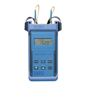
1 Introducing the FVA-60B Variable Optical Attenuator The FVA-60B is a variable optical attenuator used for bit error rate and system testing, optical margin analysis, calibration verification and component testing. It can be configured for singlemode or multimode fibers. Calibrated wavelengths are either 1310/1550 nm or 850/1300 nm respectively. -
Page 7: Secondary Functions Keypad
To access a secondary function, press shift, then the corresponding key. Connector Panel Description Connects unit to Supplies DC power to unit computer for remote and recharges built-in control via RS-232 Ni-MH battery pack interface cable INPUT OUTPUT RS-232 12 VDC Input optical port Output optical port FVA-60B FVA-60B... -
Page 8: Conventions
Introducing the FVA-60B Variable Optical Attenuator Conventions Before using the product described in this manual, you should understand the following conventions: ARNING Indicates a potentially hazardous situation which, if not avoided, could result in death or serious injury. Do not proceed unless you understand and meet the required conditions. -
Page 9: Safety Information
Do not install or terminate fibers while a laser source is active. Never look directly into a live fiber and ensure that your eyes are protected at all times. ARNING Use of controls, adjustments and procedures for operation and maintenance other than those specified herein may result in hazardous radiation exposure. FVA-60B... -
Page 10: Operating The Fva-60B Variable Optical Attenuator
The Absolute mode displays the current wavelength and attenuation settings. It is selected by default when turning on the FVA-60B. Scanning is used to set a new attenuation value. If you turn off the unit while a scan is in progress, it will be completed the next time you turn the unit on. -
Page 11: Using The Relative Mode
(that is, 00.00 dB). If you now vary the attenuation, the smaller digits display the total attenuation introduced by the FVA-60B, while the larger digits display the relative loss (or gain) with respect to the selected reference. Using the X + B Mode... -
Page 12: Programming Wavelengths
Operating the FVA-60B Variable Optical Attenuator Programming Wavelengths The FVA-60B offers calibrated wavelength at ± 30 nm (in 10 nm steps) from the standard singlemode and multimode wavelengths. To program wavelengths: 1. Press shift/exit, then λ SELECT for three seconds. The currently selected wavelength flashes. -
Page 13: Programming The Unit
7. Press shift/exit to exit the program setup. Your program parameters have been set. Note: If you turn off the unit before exiting the program definition, all changes made during the current programming session will be lost. FVA-60B... -
Page 14: Initiating The Program Execution
To initiate the program execution: 1. Set the unit to the appropriate initial attenuation value. 2. Press program. The FVA-60B will start at the initial attenuation value and automatically increase the attenuation in accordance with the program parameters. Upon completion of the last program step, the unit resets the initial attenuation value and the program loops. -
Page 15: Using The Rs-232 Interface And Software
RS-232 kit. Refer to the README.DOC file for up-to-date information about the FVA-60B application software. To read the file, insert the disk in the floppy disk drive, then type A:README from the DOS command line. -
Page 16: Connecting The Rs-232 Interface Cable
To connect the RS-232 interface cable: 1. Turn off the unit and the computer. 2. Connect the cable to the FVA-60B appropriate port. 3. Connect the DB-25 or DB-9 connector to COM 1 or COM 2 on the computer. Starting the Interface Application The information within square brackets is optional and depends on the configuration of your personal computer. -
Page 17: Understanding The Program Menu
The floppy disk also includes a DISPLAY.EXE file that can display the contents of the files. To view a particular file, type DISPLAY FILEPATH/FILENAME.EXT, where filepath/filename.ext is the full filename (including drive and directory) of the file you wish to view. FVA-60B... -
Page 18: Using Interface Commands
Using Interface Commands The serial communication parameters for the RS-232 interface are as follows: 9600 baud no parity 8 data bits 1 stop bit The following commands are recognized by the FVA-60B RS-232 interface: Return Characters Command Description Accepted Rejected >C<... -
Page 19: Maintenance
If any liquids are spilled on or into the unit, turn off the power immediately and let the unit dry completely. ARNING Use of controls, adjustments, and procedures for operation and maintenance other than those specified herein may result in hazardous radiation exposure. FVA-60B... -
Page 20: Cleaning Fixed Connectors
Maintenance Cleaning Fixed Connectors Regular cleaning of connectors will help maintain optimum performance. Do not try to disassemble the unit. Doing so would break the connector. To clean fixed connectors: 1. Fold a lint-free wiping cloth in four to form a square. 2. - Page 21 10. Repeat steps 7 to 9, but this time with a dry cleaning tip (2.5 mm tip provided by EXFO). Note: Make sure you don’t touch the soft end of the cleaning tip and verify the cleanliness of the cotton tip. 11. Throw out the cleaning tips after one use. FVA-60B...
-
Page 22: Cleaning Eui Connectors
Maintenance Cleaning EUI Connectors Regular cleaning of EUI connectors will help maintain optimum performance. There is no need to disassemble the unit. MPORTANT If any damage occurs to internal connectors, the module casing will have to be opened and a new calibration will be required. To clean EUI connectors: 1. - Page 23 6c. With a dry lint-free wiping cloth, gently wipe the same surfaces to ensure that the connector and ferrule are perfectly dry. 6d. Verify connector surface with a portable fiber-optic microscope (for example, EXFO’s FOMS) or fiber inspection probe (for example, EXFO’s FIP). ARNING Verifying the surface of the connector WHILE THE UNIT IS ACTIVE WILL result in permanent eye damage.
-
Page 24: Cleaning Detector Ports
Maintenance Cleaning Detector Ports Regular cleaning of detectors will help maintain measurement accuracy. MPORTANT Always cover detectors with protective caps when unit is not in use. To clean detector ports: 1. Remove the protective cap and adapter (FOA) from the detector. 2. -
Page 25: Recycling And Disposal (Applies To European Union Only)
European Union member state with legislation regarding Directive 2002/96/EC. Except for reasons of safety or environmental benefit, equipment manufactured by EXFO, under its brand name, is generally designed to facilitate dismantling and reclamation. For complete recycling/disposal procedures and contact information, visit the EXFO Web site at www.exfo.com/recycle. -
Page 26: Troubleshooting
Troubleshooting 6 Troubleshooting Solutions to Common Problems Problem Solution Display is blank Press on/off. Verify and connect AC adapter/charger. Replace 9 V battery. Connect AC adapter/charger. LO BAT is displayed Connect AC adapter/charger. LO BAT is flashing Connect AC adapter/charger. Replace 9 V battery. -
Page 27: Contacting The Technical Support Group
Contacting the Technical Support Group To obtain after-sales service or technical support for this product, contact EXFO at one of the following numbers. The Technical Support Group is available to take your calls from Monday to Friday, 8:00 a.m. to 7:00 p.m. (Eastern Time in North America). -
Page 28: Warranty
DAMAGES. Liability EXFO shall not be liable for damages resulting from the use of the product, nor shall be responsible for any failure in the performance of other items to which the product is connected or the operation of any system of which the product may be a part. -
Page 29: Exclusions
Exclusions EXFO reserves the right to make changes in the design or construction of any of its products at any time without incurring obligation to make any changes whatsoever on units purchased. Accessories, including but not limited to fuses, pilot lamps, batteries and universal interfaces (EUI) used with EXFO products are not covered by this warranty. -
Page 30: Service And Repairs
After repair, the equipment will be returned with a repair report. If the equipment is not under warranty, you will be invoiced for the cost appearing on this report. EXFO will pay return-to-customer shipping costs for equipment under warranty. Shipping insurance is at your expense. -
Page 31: Exfo Service Centers Worldwide
EXFO Service Centers Worldwide If your product requires servicing, contact your nearest authorized service center. EXFO Headquarters Service Center 400 Godin Avenue 1 866 683-0155 (USA and Canada) Quebec (Quebec) G1M 2K2 Tel.: 1 418 683-5498 CANADA Fax: 1 418 683-9224 quebec.service@exfo.com... -
Page 32: A Technical Specifications
The following technical specifications can change without notice. The information presented in this section is provided as a reference only. To obtain this product’s most recent technical specifications, visit the EXFO Web site at www.exfo.com. ation wavelengths (nm) 1310/1550 1300... - Page 33 EXFO ASIA-PACIFIC 151 Chin Swee Road SINGAPORE 169876 #03-29, Manhattan House Tel.: +65 6333 8241 · Fax: +65 6333 8242 TOLL-FREE (USA and Canada) 1 800 663-3936 © 2008 EXFO Electro-Optical Engineering Inc. All rights reserved. Printed in Canada (2008-05)
Need help?
Do you have a question about the FVA-60B and is the answer not in the manual?
Questions and answers