
Subscribe to Our Youtube Channel
Related Manuals for Common CPT-01 Series


Summary of Contents for Common CPT-01 Series
- Page 1 QUANTOMETERS series CPT-01 OPERATION MANUAL CPT – OM – 18 April 2018 PRIOR TO INSTALLATION AND START-UP READ CAREFULLY THESE INSTRUCTIONS...
-
Page 2: Table Of Contents
Contents Page DESIGN AND APPLICATION CONDITIONS CONSTRUCTION AND OPERATION III. INDEX AND MEASUREMENT OUPTUTS MARKING AND CALIBRATION OF QUANTOMETERS PACKAGING, TRANSPORTATION AND STORAGE INSTALLATION AND START-UP VII. MAINTENANCE, FAULTS , REPAIRS VIII. AUXILIARY EQUIPMENT DECLARATION OF CONFORMITY CPT- OM – 18 2018.04.30... -
Page 3: Design And Application Conditions
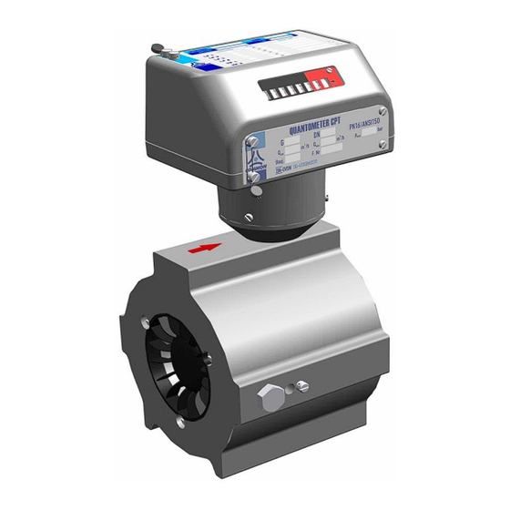
I. DESIGN AND APPLICATION CONDITIONS Design CPT-01 Turbine Quantometers are instruments used for measurement of gas volume that flows through an installation. Standard version allows to be installed where explosion hazard zones may occur (air and gas mixtures - class IIA and class IIB; with special version – also class IIC). - Page 4 Requirements met by the use of LF and HF pulse emitters (NAMUR) compliant with the following harmonized standards: EN 60947-5-2:2007, EN 60947-5-6:2000). 5. Accuracy class (OIML R 137-1&2:2012 (E) table 2) 6. Metrology parameters see Table 2 7. Operating position HV (horizontal or vertical) 8.
- Page 5 Nominal Pressure diameter Gas meter Maximum loss Emitter constant (connection size flow at Q Minimum flow at rangeability (for HF approximate) thread) ∆p 1:10 1:20 1:30 HF1, HF2 [mbar] [imp/m [imp/m [imp/m DN 25 G 16 9770 113600 (1” or 1¼”) G 25 8710 101300...
-
Page 6: Construction And Operation
II. CONSTRUCTION AND OPERATION The turbine quantometer operation is based on the proportionality of the rotational speed of the turbine wheel to the linear velocity thus to the flowing gas volume. Gas entering the meter (Fig. 2) is directed through the inlet flow straightener into the measurement assem- bly and causes the rotation of the turbine wheel. - Page 7 2. Measurement assembly. It consists of the turbine wheel, the turbine wheel housing, the measurement assembly housing, shafts and gears. The turbine wheel is placed in the axis of the quantometer body and is provided with high precision bearings. The standard version uses bearings with a supply of grease.
-
Page 8: Index And Measurement Ouptuts
III. INDEX AND MEASUREMENT OUTPUTS The reading assemblies of the CPT-01 Quantometer consist of a mechanical index with incorporated electric signal outputs, a pressure tap and a tap for installation of an external HF pulse transmitter (from the turbine wheel). These outputs enable the control of the instrument operation and connections of external devices. - Page 9 and covered by a protective cap. The mechanical output (Fig. 3a) may be used to drive exter- nal devices. The rotational speed of the shaft is identical to the speed of the fastest counter drum. The shaft rotates in a clockwise direction. Maximum allowable momentum on the out- put shaft tip is 0.25 Nmm (Fig.
- Page 10 II 1G Ex ia IIC T4...T6 or II 2G Ex ia IIC T4...T6 type CLFK-03 by Common S.A. type CLFW-01 by Common S.A. (1) – required linear characteristics of the emitter power circuit. (2) – only for versions following the certificate No. IECEx KDB 15.0004...
- Page 11 The protection type of the transmitters should be at least II 2G Ex ib IIC T5 Gb. These conditions are met by the following transmitters: CHFI-03 by Common S.A., equipped with Bi3-EG12-RY1/S1000 sensors (Hans Turck GmbH, Certificate No.: KEMA 02ATEX1152X marking II 1G Ex ia IICT4...T6 or...
- Page 12 Permissible supply parameters of the above mentioned transmitters from intrinsically safe circuits, maximum inductance and internal capacitance of the transmitters are as follows: Pi = 200 mW, Li = 350 μH, Ci = 180 nF. - CHFI-03 Ui = 20 V, Ii = 60 mA, The application conditions and supply parameters are marked on the transmitter housing.
- Page 13 The distributed parameters of cables (Ck), (Lk) should be taken as: The least favorable parameters given by the cable manufacturer or Parameters measured in accordance to EN 60079-14 or 200pF/m & 1H/m or 30H/ where the connection consists of 2 or 3 wires (with or without shield) Nominal operating parameters of the emitters: reed contact emitter / Wiegand emitter CLFK-03 / CLFK-04 / CLFW-01 / CLFW-02 / CLFW-04...
- Page 14 Temperature measurement outputs. CPT-01 quantometers are equipped with temperature measurement outputs only when delivered as a special order version; temperature sockets are not available in standard ver- sions. Temperature measurement outputs are located on both sides of the main body of the meter (Fig.
-
Page 15: Marking And Calibration Of Quantometers
IV. MARKING AND CALIBRATION OF THE QUANTOMETERS Basic specification of the gas meter, serial number and production year is shown in the nameplates (Fig. 8 and Fig. 9). The plates are fixed to the index housing by means of screws. Two first digits of the serial number indicate the gas meter size code, according to Table 2. - Page 16 Fig. 9. Special version nameplate flow direction pressure output example of oil type mechanical output HF emitter type plate Fig.10. Information marks Each quantometer is calibrated in the manufacturer’s laboratory or other recognized laboratory. The calibration certificate may be delivered on customer’s request. Connections that are not being dismantled during the quantometer installation are protected with seals of the manufacturer or of a recognized laboratory (P1, P2, P3, P4, P6 and P8 Fig.
- Page 17 Fig.11a. Location of seals on the CPT-01 Quantometers (old version) Location of additional seals on the CPT-01 with Fig.11b. Encoder CWSL-N. CPT- OM – 14 2014.10.30...
- Page 18 Fig.11c. Location of seals on the CPT-01 Quantometers (new version) Protective seals installed on the pressure sensor tapping (P5), on the temperature outputs (P9), on the HF transmitter (P7) and optional on the mechanical output (P10) are marked by the manufacturer, by the gas supplier or by the authorized installer.
-
Page 19: Packaging, Transportation And Storage
Each CPT-01 Qantometer manufactured by COMMON S.A. is provided with the following accessories: 6-pin plug “Tuchel” C091 31H006 100 2 that may be used for connecting a volume corrector’s or a data logger’s low frequency electric output (if the volume corrector... - Page 20 CPT- OM – 14 2014.10.30...
- Page 21 CPT- OM – 14 2014.10.30...
- Page 22 CPT- OM – 14 2014.10.30...
- Page 23 CPT- OM – 14 2014.10.30...
- Page 24 CPT- OM – 14 2014.10.30...
-
Page 25: Installation And Start-Up
VI. INSTALLATION AND START-UP Prior to the installation of the quantometer check whether it has been selected properly, in accordance with the operating parameters of the system. In particular, attention should be paid to the following information contained in the nameplate: ... - Page 26 [5] New version DN50 [6] New version DN50 with external thread with internal thread Fig.12. Installation dimensions quantometers series CPT-01 CPT- OM – 14 2014.10.30...
- Page 27 The quantometer should be installed in piping of the appropriate nominal diameter. Proper alignment of the meter and pipe flanges should be assured. It is recommended to install ap- propriate upstream and downstream pipe sections. Turbine quantometer in standard version (Fig. 12 [1]) has a flat face in order to be installed in the pipework between PN16 and PN20 (ANSI150) flanges.
- Page 28 HE MANUFACTURER IS NOT LIABLE FOR ANY DAMAGES TO THE QUANTOMETER DUE TO IMPROPER FILTRATION OF THE FLOWING GAS The user of the meter should pay special attention to some risk related to gas flow changes. If for a longer time, after commissioning, the flow in the piping was relatively low the impuri- ties (e.g.
- Page 29 5 to 10 nominal pipe diameters. The orifice plate size is de- termined individually, depending on the nominal pipe diameter, flow, pressure and tempera- ture of the gas. On request COMMON S.A. may provide appropriate orifices. After installation of the quantometer check whether indications of the index are proper. Each...
-
Page 30: Maintenance, Faults, Repairs
1.600.000 For lubrication it is recommended to use LUBRINA oil or VR09 oil, which are distrib- uted by COMMON S.A.. For turbine quantometers DN65 and DN80 the recommended oil is /s (cSt) at the temperature of 20ºC. VR09 or LUBRINA L12 with a viscosity of about 12 mm... -
Page 31: Auxiliary Equipment
VIII. AUXILIARY EQUIPMENT Lubrication kit for quantometers Special version of CPT-01 turbine quantometers can be adapted for external lubrica- tion. They are then fitted with the oil feed to bearings which is completed with a pressure check valve. Lubrication is carried out with the use of kit supplied with a quantometer: ... - Page 32 b. Set up the oil injection kit, c. Draw the appropriate amount of oil (see Table 4) into syringe or into special pump, d. Press the tip of the syringe or tip of the special pump into the hole of the valve, e.
- Page 33 NOTE ! CLFK-04 & CLFW-04 transmitters must not be used interchangeably. Index head is adapted to one type of transmitter only. CWSL Encoder (option) CWSL Encoder can be connected to the optional mechanical output. There are 3 ver- sions of (optional) Encoders available: CWSL-N, CWSL-A, CWSL-M (Fig. 23). Data sent from CWSL-N are equal to data on the index.
- Page 34 In order to convert gas volume from operating into base conditions it is often required (or recommended) to use electronic volume converters. Common S.A. is also the manufactur- er of such devices, e.g. volume correctors CMK-03 (VPTZ), CRS-03 (VTZ) and data loggers CRI-02.
- Page 35 Notice: Technical specification and construction may change due to improvements. This publication serves as general information only, and all specifications are subject to confirmation by COMMON S.A. CPT- OM – 14 2014.10.30...
Need help?
Do you have a question about the CPT-01 Series and is the answer not in the manual?
Questions and answers