
Related Manuals for Common CGR-FX


Summary of Contents for Common CGR-FX
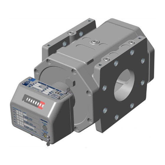
- Page 1 CGR-FX ROTARY GAS METERS OPERATING MANUAL CGR-FX / OM 16-06 June 2016 PRIOR TO INSTALLATION AND START-UP PLEASE READ CAREFULLY THESE INSTRUCTIONS...
-
Page 2: Table Of Contents
DESIGN AND FUNCTION III. READOUT DEVICE AND MEASUREMENT OUTPUTS LABELLING AND PROTECTION PACKAGING, TRANSPORT AND STORAGE INSTALLATION AND OPERATION VII. OPERATION MONITORING, MAINTENANCE, FAILURES, REPAIRS VIII. ADDITIONAL EQUIPMENT LIST OF STANDARDS AND TECHNICAL SPECIFICATIONS CGR-FX / OM 16-06 June 2016... -
Page 3: Intended Use And Conditions Of Use
CGR-FX Rotary Gas Meters enable the gas flows to be measured in any from among four directions (horizontally – from left to right side, or from right to left side, and vertically –... - Page 4 LF and HF pulse emitters (NAMUR) compliant with the following harmonized standards: EN 60947-5-2:2011, EN 60947-5-6:2000. Table 1. Physical properties of the most common gases and gas mixtures that may be measured with CGR-FX. Densities under pressure of 101.325 kPa at 20...
- Page 5 Fig. 1. Pressure drop coefficient as a function of the relative flow Q/Q CGR-FX / OM 16-06 June 2016...
- Page 6 Table 2a. Basic metrological parameters of CGR-FX gas meters in aluminium bodies. ∆p B∆p pulse value Maxi- minimum Series. Nominal meter pulse cyclic pressure drop at (approx) (range) at Q diameter size. value volume flow (range) flow. [mm] [–] [–] [imp./m...
-
Page 7: Design And Function
(4) – pressure drop on damaged meter and open double by-pass, Table 2b. Basic metrological parameters of CGR-FX gas meters in cast iron bodies. ∆p B∆p pulse minimum pulse cyclic Series nominal meter maximum pressure drop at (range) value flow... - Page 8 The assembly is also complete with sockets for transmitting the low and high frequency electric signals outside the gas meter. As an option the index head may be provided with mechanical drive shaft. CGR-FX / OM 16-06 June 2016...
- Page 9 Fig. 3. Cross-section of the rotary gas meters CGR-FX CGR-FX / OM 16-06 June 2016...
-
Page 10: Readout Device And Measurement Outputs
III. READOUT DEVICE AND MEASUREMENT OUTPUTS The gas meters CGR-FX are equipped with a readout device in the form of a mechanical counter and electric signal outputs. The index head may be provided with: - mechanical output (drive shaft), - replaceable HF pulse sensor installed in the index head support, The meter housing is provided with pressure and temperature measurement taps (options). - Page 11 (see section VII). Inductive HF emitter type CHFI-04 by Common S.A. should be used as the external control element. The type plate of the gas meter includes the value of the constant for emitters HF1 and HF2; this value is also...
- Page 12 After disconnecting the control element, the socket is tightly plugged and sealed (Fig. 9). In line with the conditions for use, the CGR-FX gas meters should be equipped with emitters allowing for at least II 2G Ex ib IIC T5 Gb protection.
- Page 13 LFK and AFK emitters only. Temperature measurement output. The rotary gas meters CGR-FX allows temperature measurements only when delivered as a special order version; temperature measurements are not available in the standard version. Temperature probes are not a part of the meter with the temperature tapping and it is necessary to order them separately.
- Page 14 The outputs are used to connect pressure transducers, either directly to the socket (Fig. 6b) or via three-way valves. Outputs that are not in use are blinded with plugs (Fig. 6a). Both plugs and sockets may be protected by installation seals. CGR-FX / OM 16-06 June 2016...
-
Page 15: Labelling And Protection
Information on the basic technical parameters of the gas meter along with the serial number and manufacture year is listed on rating plates (Figs. 8a, 8b and 8c) fixed to the counter casing. Fig. 8a. Type plates – special version HTR CGR-FX / OM 16-06 June 2016... - Page 16 Fig. 8b. Type plates – standard version for IIA and IIB explosion groups Fig. 8c. Type plates – special version for IIC explosion group CGR-FX / OM 16-06 June 2016...
- Page 17 Following verification by the authorized manufacturer laboratory, each gas meter is protected with seals placed in locations shown in Fig.9. On customer’s request the gas meter may be delivered along with the calibration certificate. Fig. 9. Locations of seals on CGR-FX rotary gas meter. CGR-FX / OM 16-06 June 2016...
-
Page 18: Packaging, Transport And Storage
Before the end of the verification period, the gas meter should be submitted for secondary verification in an authorized laboratory. Re-calibration of meters may be performed by COMMON S.A., in our own laboratory. It is also possible to make necessary adjustments and repairs, if required. - Page 19 6. It is not required for the gas meter to be primed with oil during warehouse storage. CGR-FX / OM 16-06 June 2016...
- Page 20 Fig. 11a. Packaging of the CGR-FX gas meters (aluminum bodies) CGR-FX / OM 16-06 June 2016...
- Page 21 Fig. 11b. Packaging of the CGR-FX gas meters (cast iron bodies) CGR-FX / OM 16-06 June 2016...
-
Page 22: Installation And Operation
, may be exceeded by not more than 25% for not longer than 30 minutes. Rotary gas meters CGR-FX may be operated in the following four operating positions (Figure 12 a, b, c, d): Fig. 12. Operating positions of the CGR-FX rotary gas meter. - Page 23 Dimensions listed in Tables 4a, 4b, 4c, 4d and illustrated in Figure 14 may be helpful when designing the location for the installation of the gas meter. Table 4a. Basic dimensions and weights of CGR-FX gas meters in aluminium bodies.
- Page 24 Table 4b. Basic dimensions and weights of CGR-FX gas meters in cast iron bodies. Qmax Weight at V cycl Series m3/h 0.50 0.50 0.50 0.50 0.81 "171" 100s 0.50 100p 0.81 100w 1.24 160s 0.81 160p 1.24 250s 1.24 160w 2.00...
- Page 25 The manufacturer is not responsible for any damages or stoppage of the gas meter resulting from insufficient filtration of the gas flowing through the meter. Fig. 14. Basic dimensions of CGR-FX rotary gas meters. The user should be aware of certain risks associated with changes in the gas flow intensity. If the gas flow was relatively low for a long time after system initiation, the assembly-related contaminants (e.g.
- Page 26 oil filler plug (Fig. 15a) – standard version, pressure oil refill valve (Fig. 15b) – special version. Each standard CGR-FX gas meter may be transformed into special version by installation of a pressure valve and an oil refill assembly.
- Page 27 Detailed information is presented in Section VIII. Additional equipment. Caution! The pressure valve must not be removed when the gas meter is installed in the system under working pressure CGR-FX / OM 16-06 June 2016...
- Page 28 Common S.A. may design and deliver appropriate orifice at customer's request. Counter readout correctness should be checked after installing the gas meter. Every barrel of the counter should turn smoothly and a full turn of a barrel should turn the neighbouring left barrel by 1/10 of a full turn.
-
Page 29: Operation Monitoring, Maintenance, Failures, Repairs
If the counter is not equipped with a HF emitter, an external HF emitter (type CHFI-04 by COMMON S.A.) should be connected to act as a control element (Fig. 17). For more information on the HF transmitter type CHFI-04 in Chapter VIII. ADDITIONAL EQUIPMENT. - Page 30 The gas meters CGR-FX are complete with a system for lubrication of rotors and inner gears. The remaining mechanisms are furnished with bearings complete with lubricant reserves. Therefore, the only activity required for the maintenance of the gas meters is the monitoring of the oil level and possibly oil refill.
-
Page 31: Additional Equipment
Before starting the oil refill procedure, stop the flow of the gas in the measurement system and wait several minutes until the oil level is stabilized in the gas meter. Fig. 18. Oil refill procedure in pressurized conditions. CGR-FX / OM 16-06 June 2016... - Page 32 Fig. 19. CHFI-04 replaceable HF transmitter Internal by-pass CGR-FX Rotary Meters may be provided with internal by-pass, as an option. The by- pass is designed so as to provide continuous gas flow in case of meter failure (blockage of rotors) . When a failure situation occurs the membrane breaks and opens the gas flow through the by-pass that omits the meter measurement chamber.
- Page 33 Fig. 20a. Connection of the internal by-pass. Fig. 20b. By-pass rating plate. NOTES: 1. It is recommended to install the CGR-FX meter with by-pass on the inlet side (higher pressure) 3. Pressure regulators with slum shut valves should be so as they do not engage earlier than the by-pass is opened .
- Page 34 CKMT valve (Fig. 22) allowing the pressure being disconnected from the sensor for the removal and inspection thereof. Fig. 22. A three-way CKMT valve CGR-FX / OM 16-06 June 2016...
- Page 35 Un- used electrical outlet sockets must remain plugged with factory-made plugs and installa- tion seals. CGR-FX / OM 16-06 June 2016...
-
Page 36: List Of Standards And Technical Specifications
Note: Common S.A. reserves the right to modify the design of the gas meters while retaining the compliance with relevant standards and requirements regarding accuracy and safety of operation.
Need help?
Do you have a question about the CGR-FX and is the answer not in the manual?
Questions and answers